cruise control JAGUAR XFR 2010 1.G User Guide
[x] Cancel search | Manufacturer: JAGUAR, Model Year: 2010, Model line: XFR, Model: JAGUAR XFR 2010 1.GPages: 3039, PDF Size: 58.49 MB
Page 891 of 3039
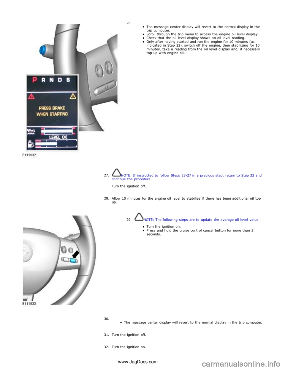
26.
The message center display will revert to the normal display in the
trip computer.
Scroll through the trip menu to access the engine oil level display.
Check that the oil level display shows an oil level reading.
Only after having started and run the engine for 10 minutes (as
indicated in Step 22), switch off the engine, then stabilizing for 10
minutes, take a reading from the oil level display and, if necessary
top up with engine oil.
27.
NOTE: If instructed to follow Steps 23-27 in a previous step, return to Step 22 and
continue the procedure.
Turn the ignition off.
28.
Allow 10 minutes for the engine oil level to stabilize if there has been additional oil top
up.
29. NOTE: The following steps are to update the average oil level value.
Turn the ignition on.
Press and hold the cruise control cancel button for more than 2
seconds.
30.
The message center display will revert to the normal display in the trip computer.
31. Turn the ignition off.
32. Turn the ignition on. www.JagDocs.com
Page 897 of 3039
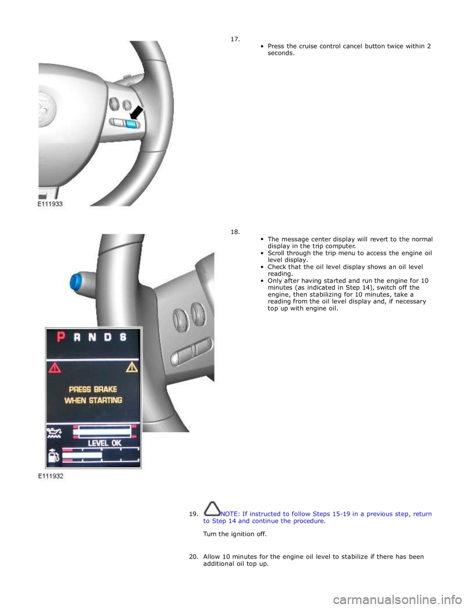
17.
18.
Press the cruise control cancel button twice within 2
seconds.
The message center display will revert to the normal
display in the trip computer.
Scroll through the trip menu to access the engine oil
level display.
Check that the oil level display shows an oil level
reading.
Only after having started and run the engine for 10
minutes (as indicated in Step 14), switch off the
engine, then stabilizing for 10 minutes, take a
reading from the oil level display and, if necessary
top up with engine oil.
19. NOTE: If instructed to follow Steps 15-19 in a previous step, return
to Step 14 and continue the procedure.
Turn the ignition off.
20. Allow 10 minutes for the engine oil level to stabilize if there has been
additional oil top up.
Page 898 of 3039
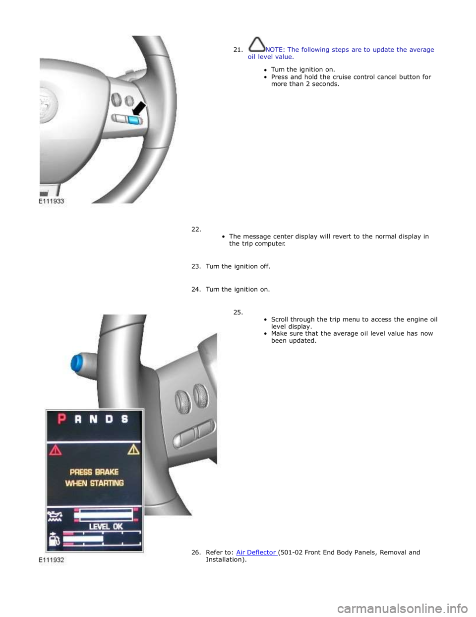
21.
NOTE: The following steps are to update the average
oil level value.
Turn the ignition on.
Press and hold the cruise control cancel button for
more than 2 seconds.
22.
The message center display will revert to the normal display in
the trip computer.
23. Turn the ignition off.
24. Turn the ignition on.
25.
Scroll through the trip menu to access the engine oil
level display.
Make sure that the average oil level value has now
been updated.
26. Refer to: Air Deflector (501-02 Front End Body Panels, Removal and Installation).
Page 1082 of 3039
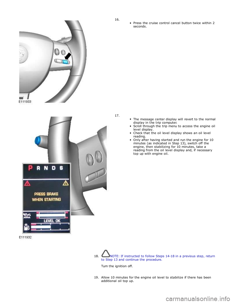
16.
17.
Press the cruise control cancel button twice within 2
seconds.
The message center display will revert to the normal
display in the trip computer.
Scroll through the trip menu to access the engine oil
level display.
Check that the oil level display shows an oil level
reading.
Only after having started and run the engine for 10
minutes (as indicated in Step 13), switch off the
engine, then stabilizing for 10 minutes, take a
reading from the oil level display and, if necessary
top up with engine oil.
18. NOTE: If instructed to follow Steps 14-18 in a previous step, return
to Step 13 and continue the procedure.
Turn the ignition off.
19. Allow 10 minutes for the engine oil level to stabilize if there has been
additional oil top up.
Page 1083 of 3039

20.
NOTE: The following steps are to update the average
oil level value.
Turn the ignition on.
Press and hold the cruise control cancel button for
more than 2 seconds.
21.
The message center display will revert to the normal display in
the trip computer.
22. Turn the ignition off.
23. Turn the ignition on.
24.
Scroll through the trip menu to access the engine oil
level display.
Make sure that the average oil level value has now
been updated.
25. Refer to: Air Deflector (501-02 Front End Body Panels, Removal and Installation).
Page 1367 of 3039
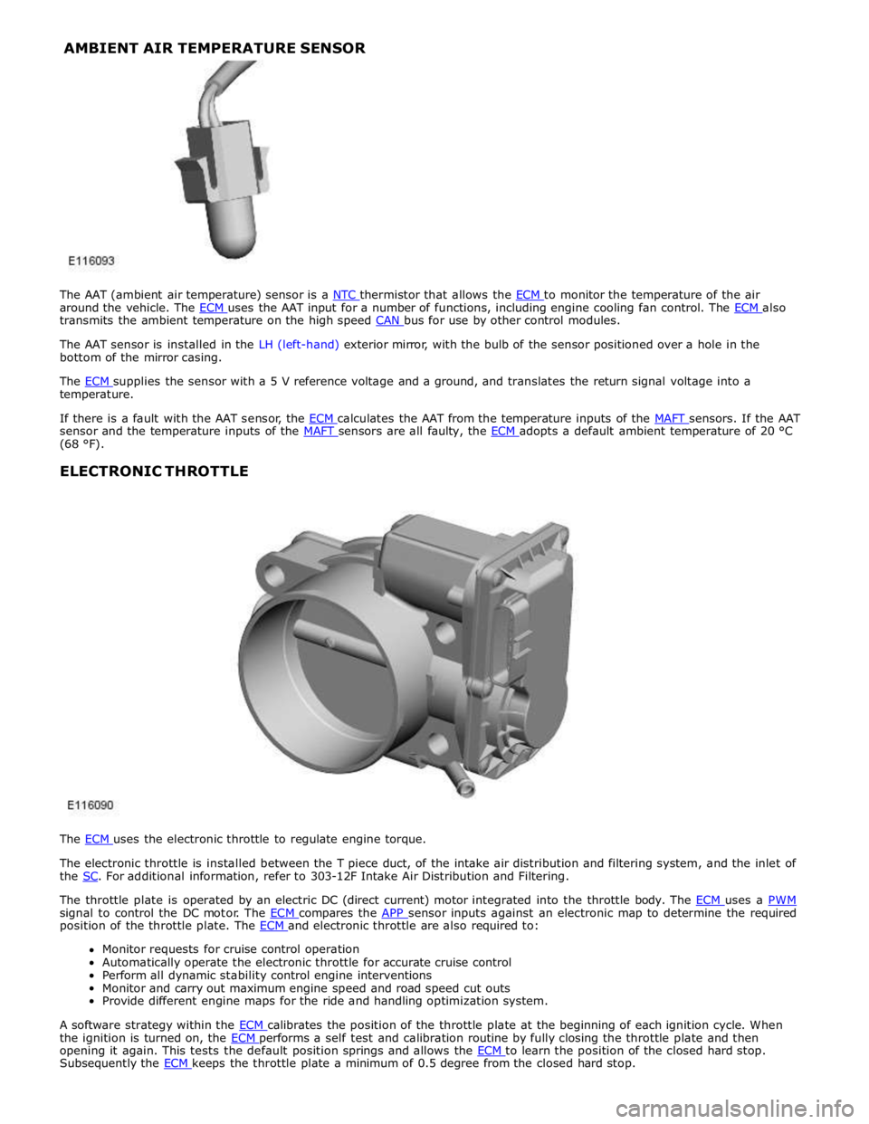
around the vehicle. The ECM uses the AAT input for a number of functions, including engine cooling fan control. The ECM also transmits the ambient temperature on the high speed CAN bus for use by other control modules.
The AAT sensor is installed in the LH (left-hand) exterior mirror, with the bulb of the sensor positioned over a hole in the
bottom of the mirror casing.
The ECM supplies the sensor with a 5 V reference voltage and a ground, and translates the return signal voltage into a temperature.
If there is a fault with the AAT sensor, the ECM calculates the AAT from the temperature inputs of the MAFT sensors. If the AAT sensor and the temperature inputs of the MAFT sensors are all faulty, the ECM adopts a default ambient temperature of 20 °C (68 °F).
ELECTRONIC THROTTLE
The ECM uses the electronic throttle to regulate engine torque.
The electronic throttle is installed between the T piece duct, of the intake air distribution and filtering system, and the inlet of
the SC. For additional information, refer to 303-12F Intake Air Distribution and Filtering.
The throttle plate is operated by an electric DC (direct current) motor integrated into the throttle body. The ECM uses a PWM signal to control the DC motor. The ECM compares the APP sensor inputs against an electronic map to determine the required position of the throttle plate. The ECM and electronic throttle are also required to: Monitor requests for cruise control operation
Automatically operate the electronic throttle for accurate cruise control
Perform all dynamic stability control engine interventions
Monitor and carry out maximum engine speed and road speed cut outs
Provide different engine maps for the ride and handling optimization system.
A software strategy within the ECM calibrates the position of the throttle plate at the beginning of each ignition cycle. When the ignition is turned on, the ECM performs a self test and calibration routine by fully closing the throttle plate and then opening it again. This tests the default position springs and allows the ECM to learn the position of the closed hard stop. Subsequently the ECM keeps the throttle plate a minimum of 0.5 degree from the closed hard stop. AMBIENT AIR TEMPERATURE SENSOR
Page 1373 of 3039

DTC Description Possible Causes Action B10AC-81
Cruise Control Switch -
invalid serial data received
The Engine Control Module
(ECM) has received an invalid
command from the steering
wheel switch pack Clear the DTC and press all the steering wheel
switches, re-check for DTCs. Refer to the
electrical circuit diagrams and check the Cruise
control switch circuit for open circuit, short to
power, short to ground, disconnected. Check
and install a new Steering Wheel Module (SWM) as required. B10AC-82 Cruise Control Switch - alive / sequence counter incorrect / not updated
Cruise Buttons alive counter is
not incrementing. Which
suggests that the LIN bus is
faulty
Steering Wheel Module (SWM) is
not connected
Steering Wheel Module (SWM)
failure Refer to the electrical circuit diagrams and
check the Cruise control switch circuit for open
circuit, short to power, short to ground,
disconnected. Check and install a new Steering
Wheel Module (SWM) as required. B10AC-83
Cruise Control Switch - value
of signal protection
calculation incorrect
Cruise buttons checksum
incorrect, incorrect cruise
switches fitted to vehicle Check and install new cruise switches as
required. B10AC-96
Cruise Control Switch -
component internal failure
Cruise control switch circuit,
open circuit, short to power,
short to ground, disconnected
Cruise Control Switch failure
Steering Wheel Module (SWM)
failure Check for related DTCs in other Central
Junction Box (CJB)s. Refer to the electrical
circuit diagrams and check the Cruise control
switch circuit for open circuit, short to power,
short to ground, disconnected. Check and
install a new cruise control switch as required.
Check and install a new Steering Wheel
Module (SWM) as required. B10FF-68
Ignition Control - Event
information
Spark plug(s) fault
Wiring harness fault
Ignition coil(s) fault Refer to repair manual and check spark plug(s)
for condition and security. Replace any
defective components as required. Refer to
electrical wiring diagrams and check ignition
coil circuit for intermittent open circuit, short
to power, short to ground. Check and install a
new coil(s) as required. B11DB-01
Battery Monitoring Module -
General Electrical Failure
Charging system fault Battery
monitoring signal line
circuit fault
Vehicle battery fault Refer to electrical wiring diagrams and check
charging system for faults. Perform any repairs
required. Refer to the electrical wiring
diagrams and check the Battery Monitoring
System (BMS) module circuit for open circuit,
short to ground, short to power. Refer to the
battery care manual and check and install a
new battery. B11DB-87
Battery Monitoring Module -
missing message
Battery signal line circuit fault Refer to the electrical wiring diagrams and
check the Battery Monitoring System (BMS)
module circuit for open circuit, short to ground,
short to power. B1206-68
Crash Occurred - event
information
Engine control Module (ECM) has
detected the vehicle has crashed
- event information DTC only Refer to the electrical circuit diagrams and
check the Engine Control Module (ECM) to
Restraints Control Module (RCM) circuit for
short to ground, short to power, open circuit.
Repair circuit as required, clear DTC and retest
system to confirm repair. C0031-00
Left Front Wheel Speed
Sensor - No sub type
information
Invalid data received from
Anti-lock Braking System (ABS)
module - left front wheel speed
signal fault Check Anti-lock Braking System (ABS) module
for related DTCs and refer to relevant DTC
Index. C0034-00
Right Front Wheel Speed
Sensor - No sub type
information
Invalid data received from
Anti-lock Braking System (ABS)
module - right front wheel speed
signal fault Check Anti-lock Braking System (ABS) module
for related DTCs and refer to relevant DTC
Index. C0037-00
Left Rear Wheel Speed
Sensor - No sub type
information
Invalid data received from
Anti-lock Braking System (ABS)
module - left rear wheel speed
signal fault Check Anti-lock Braking System (ABS) module
for related DTCs and refer to relevant DTC
Index. C003A-00
Right Rear Wheel Speed
Sensor - No sub type
information
Invalid data received from
Anti-lock Braking System (ABS)
module - right rear wheel speed
signal fault Check Anti-lock Braking System (ABS) module
for related DTCs and refer to relevant DTC
Index.
Page 1374 of 3039

Published: 11-May-2011
Electronic Engine Controls - V8 S/C 5.0L Petrol - Powertrain Control Module
(PCM) Long Drive Cycle Self-Test
General Procedures
WARNING: Where possible, all road tests should be on well surfaced and dry roads. Always comply with speed limits and
local traffic regulations.
NOTES:
This procedure is an overcheck only. If fault codes are found, interrogation of the relevant system must be carried out and
claimed against.
The vehicle must exceed 50mph (80 km/h) during the road test.
1. Connect the diagnostic equipment to the vehicle.
2. Follow on screen prompts and check for engine management fault codes.
3. Clear the fault codes following the on screen procedure.
4. Disconnect the diagnostic equipment from the vehicle.
5. NOTE: Make sure cruise control is not engaged. Make sure
the engine temperature is above 60 ºC (140 ºF).
Carry out a road test and perform the following operations.
1. Accelerate to 55 mph (88 km/h) in 5th gear and cruise for 2
minutes with the engine speed at or above 1800rpm.
2. Lift off the throttle and allow the vehicle to decelerate until the
engine speed is less than 1000 rpm.
3. Stop the vehicle.
4. Release brake, allow the vehicle to move with no throttle for 1
minute.
5. Road test is now complete.
6. Connect the diagnostic equipment to the vehicle.
7. NOTE: If fault codes are found, interrogation of the relevant
system must be carried out and claimed against.
Follow on screen prompts and check for engine management fault codes.
8. Disconnect the diagnostic equipment from the vehicle.
Page 1651 of 3039

DTC Description Possible Causes Action for further assistance P0501-62
Vehicle Speed Sensor A
Range/Performance - Signal
compare failure
Vehicle speed - range
performance
Check ABS/TCM for related DTCs and refer
to relevant DTC Index P0504-00 Brake Switch A / B Correlation
- No sub type information
The brake pressure reading
does not agree with the
brake light switch value
Carry out any pinpoint tests associated with
this DTC using the manufacturer approved
diagnostic system. Refer to the electrical
circuit diagrams and check brake switch
circuits for short, open circuit, high
resistance P0504-01 Brake Switch A / B Correlation
- General electrical failure
Brake switch high fault:
- Brake lights stuck
on
- Gearshift interlock
inoperative
- Speed control
inoperative
Brake switch low fault:
- Brake lights
inoperative
- Gearshift stuck in
Park
- Reduced engine
braking
Carry out any pinpoint tests associated with
this DTC using the manufacturer approved
diagnostic system. Refer to the electrical
circuit diagrams and check brake switch
circuits for short, open circuit, high
resistance P0566-00
Cruise Control OFF Signal - No
sub type information
Speed control Cancel
switch 2 stuck closed
Refer to the electrical circuit diagrams and
check speed control switch circuits for short,
open circuit. Check for stuck switch. Check
and install a new speed control switch as
required P0567-00
Cruise Control DECREASE
DISTANCE Signal - No sub
type information
Speed control Resume
switch 7 stuck closed
Refer to the electrical circuit diagrams and
check speed control switch circuits for short,
open circuit. Check for stuck switch. Check
and install a new speed control switch as
required P0568-00
Cruise Control INCREASE
DISTANCE Signal - No sub
type information
Speed control Accel Set
Plus Switch 6 stuck closed
Check and install a new speed control
switch as required P0569-00
Cruise Control COAST Signal -
No sub type information
Speed control Coast Set
Minus switch 3 stuck
closed
Refer to the electrical circuit diagrams and
check speed control switch circuits for short,
open circuit. Check for stuck switch. Check
and install a new speed control switch as
required P056A-00
Cruise Control INCREASE
DISTANCE Signal - No sub
type information
Speed control Headway
Plus switch 4 stuck closed
Refer to the electrical circuit diagrams and
check speed control switch circuits for short,
open circuit. Check for stuck switch. Check
and install a new speed control switch as
required P056B-00
Cruise Control DECREASE
DISTANCE Signal - No sub
type information
Speed control Headway
Minus switch 5 stuck
closed
Refer to the electrical circuit diagrams and
check speed control switch circuits for short,
open circuit. Check for stuck switch. Check
and install a new speed control switch as
required P0571-62
Brake Switch A Circuit - Signal
compare failure
Plausibility error
Refer to the electrical circuit diagrams and
check brake light switch signal circuits for
short, open circuit. Check and install a new
brake light switch as required P0575-01
Cruise Control Input Circuit -
General electrical failure
General electrical failure
Check speed control system for related
DTCs and refer to relevant DTC Index. Carry
out CAN network integrity tests using the
Page 1652 of 3039

DTC Description Possible Causes Action manufacturer approved diagnostic system P0576-16
Cruise Control Input Circuit
Low - Circuit voltage below
threshold
Circuit voltage below
threshold
Check speed control system for related
DTCs and refer to relevant DTC Index. Carry
out CAN network integrity tests using the
manufacturer approved diagnostic system P0577-17
Cruise Control Input Circuit
High - Circuit voltage above
threshold
Circuit voltage above
threshold
Check speed control system for related
DTCs and refer to relevant DTC Index. Carry
out CAN network integrity tests using the
manufacturer approved diagnostic system P0578-00
Cruise Control Multi-Function
Input A Circuit Stuck - No sub
type information
One of speed control
switches stuck
Check for stuck speed control switch, install
a new switch pack as required P0578-1C
Cruise Control Multi-Function
Input A Circuit Stuck - Circuit
voltage out of range
Circuit voltage out of range
Refer to the electrical circuit diagrams and
check speed control switch circuits for short,
open circuit. Check for stuck switch. Check
and install a new speed control switch as
required P0579-1C
Cruise Control Multi-Function
Input A Circuit
Range/Performance - Circuit voltage out of range
Speed control switch pack
internal failure
Check and install a new speed control
switch pack as required P0579-29
Cruise Control Multi-Function
Input A Circuit
Range/Performance - Signal
invalid
Signal invalid
Refer to the electrical circuit diagrams and
check speed control switch circuits for short,
open circuit. Check for stuck switch. Check
and install a new speed control switch as
required P0590-00
Cruise Control Multi-Function
Input B Circuit Stuck - No sub
type information
Active speed limiter fault
Check for active speed limiter fault, install a
new transmission shift module as required