sensor JAGUAR XFR 2010 1.G Workshop Manual
[x] Cancel search | Manufacturer: JAGUAR, Model Year: 2010, Model line: XFR, Model: JAGUAR XFR 2010 1.GPages: 3039, PDF Size: 58.49 MB
Page 1588 of 3039
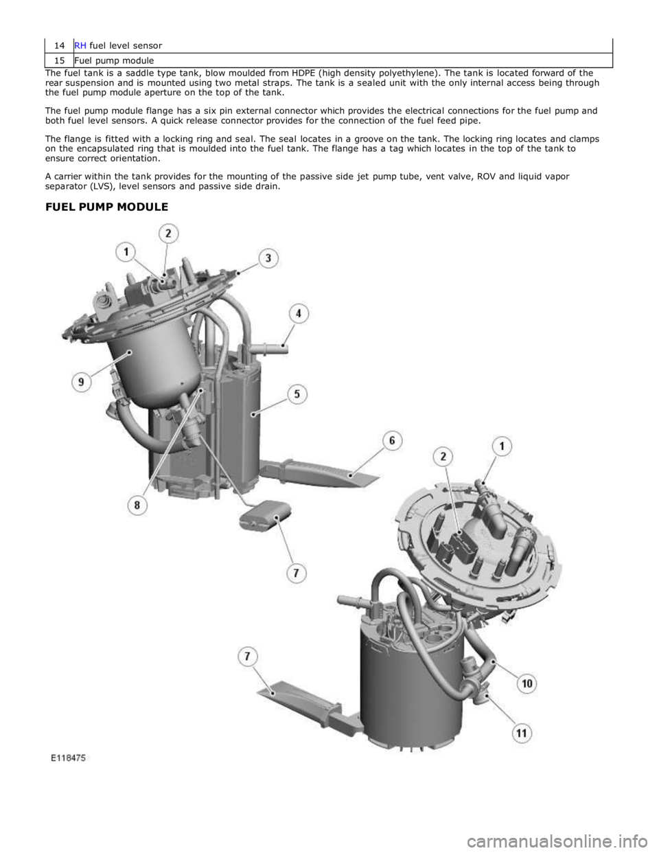
15 Fuel pump module The fuel tank is a saddle type tank, blow moulded from HDPE (high density polyethylene). The tank is located forward of the
rear suspension and is mounted using two metal straps. The tank is a sealed unit with the only internal access being through
the fuel pump module aperture on the top of the tank.
The fuel pump module flange has a six pin external connector which provides the electrical connections for the fuel pump and
both fuel level sensors. A quick release connector provides for the connection of the fuel feed pipe.
The flange is fitted with a locking ring and seal. The seal locates in a groove on the tank. The locking ring locates and clamps
on the encapsulated ring that is moulded into the fuel tank. The flange has a tag which locates in the top of the tank to
ensure correct orientation.
A carrier within the tank provides for the mounting of the passive side jet pump tube, vent valve, ROV and liquid vapor
separator (LVS), level sensors and passive side drain.
FUEL PUMP MODULE
Page 1589 of 3039
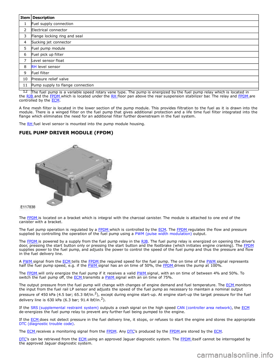
1 Fuel supply connection 2 Electrical connector 3 Flange locking ring and seal 4 Sucking jet connector 5 Fuel pump module 6 Fuel pick up filter 7 Level sensor float 8 RH level sensor 9 Fuel filter 10 Pressure relief valve 11 Pump supply to flange connection 12 The fuel pump is a variable speed rotary vane type. The pump is energized by the fuel pump relay which is located in the RJB and the FPDM which is located under the RH floor pan above the rear suspension stabilizer bar. The relay and FPDM are controlled by the ECM.
A fine mesh filter is located in the lower section of the pump module. This provides filtration to the fuel as it is drawn into the
module. There is a winged filter on the fuel pump that gives additional protection and a life time fuel filter integrated into the
flange which eliminates the need for an additional filter further downstream in the fuel system.
The RH fuel level sensor is mounted into the pump module housing.
FUEL PUMP DRIVER MODULE (FPDM)
The FPDM is located on a bracket which is integral with the charcoal canister. The module is attached to one end of the canister with a bracket.
The fuel pump operation is regulated by a FPDM which is controlled by the ECM. The FPDM regulates the flow and pressure supplied by controlling the operation of the fuel pump using a PWM (pulse width modulation) output.
The FPDM is powered by a supply from the fuel pump relay in the RJB. The fuel pump relay is energized on opening the driver's door, pressing the start button only or pressing the start button and the footbrake (which initiates engine cranking). The FPDM supplies power to the fuel pump, and adjusts the power to control the speed of the fuel pump and thus the pressure and flow
in the fuel delivery line.
A PWM signal from the ECM tells the FPDM the required speed for the fuel pump. The on time of the PWM signal represents half the fuel pump speed, e.g. if the PWM signal has an on time of 50%, the FPDM drives the pump at 100%.
The FPDM will only energize the fuel pump if it receives a valid PWM signal, with an on time of between 4% and 50%. To switch the fuel pump off, the ECM transmits a PWM signal with an on time of 75%.
The output pressure from the fuel pump will change with changes of engine demand and fuel temperature. The ECM monitors the input from the fuel rail LP sensor and adjusts the speed of the fuel pump as necessary to maintain a nominal output
pressure of 450 kPa (4.5 bar; 65.3 lbf/in.2
), except during engine start-up. At engine start-up the target pressure for the fuel
delivery line is 630 kPa (6.3 bar; 91.4 lbf/in.2
).
If the SRS (supplemental restraint system) outputs a crash signal on the high speed CAN (controller area network), the ECM de-energizes the fuel pump relay to prevent any further fuel being pumped to the engine.
If the ECM does not detect pressure in the fuel delivery line, it stops, or refuses to start the engine and stores the appropriate DTC (diagnostic trouble code).
The ECM receives a monitoring signal from the FPDM. Any DTC's produced by the FPDM are stored by the ECM.
DTC's can be retrieved from the ECM using an approved Jaguar diagnostic system. The FPDM itself cannot be interrogated by the approved Jaguar diagnostic system.
Page 1590 of 3039
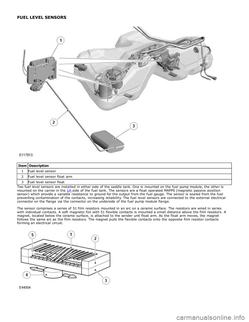
1 Fuel level sensor 2 Fuel level sensor float arm 3 Fuel level sensor float Two fuel level sensors are installed in either side of the saddle tank. One is mounted on the fuel pump module, the other is
mounted on the carrier in the LH side of the fuel tank. The sensors are a float operated MAPPS (magnetic passive position sensor) which provide a variable resistance to ground for the output from the fuel gauge. The sensor is sealed from the fuel
preventing contamination of the contacts, increasing reliability. The fuel level sensors are connected to the external electrical
connector on the flange via the connector on the underside of the fuel pump module flange.
The sensor comprises a series of 51 film resistors mounted in an arc on a ceramic surface. The resistors are wired in series
with individual contacts. A soft magnetic foil with 51 flexible contacts is mounted a small distance above the film resistors. A
magnet, located below the ceramic surface, is attached to the sender unit float arm. As the float arm moves, the magnet
follows the same arc as the film resistors. The magnet pulls the flexible contacts onto the opposite film resistor contacts
forming an electrical circuit.
Page 1596 of 3039

Visual Inspection
Mechanical Electrical
Low/contaminated fuel
Fuel supply/return line(s)
Fuel tank and filler pipe
Fuel leak(s)
Fuel filler cap
Fuel filter
Push connect fittings
Fuel pump
Fuses
Links
Relays
Fuel Pump Driver Module (FPDM)
Fuel pump module
Sensor(s)
Engine control module (ECM)
Rear Junction Box (RJB)
Restraints Control Module (RCM)
3. If an obvious cause for an observed or reported concern is found, correct the cause (if possible) before proceeding to
the next step
4. If the cause is not visually evident, verify the symptom and refer to the Symptom Chart, alternatively check for
Diagnostic Trouble Codes (DTCs) and proceed to the DTC Index
Symptom Chart
Symptom Possible Causes Action Engine cranks, but does not
fire
Engine breather system
disconnected/restricted
Ignition system
Fuel system
Electronic engine control
Ensure the engine breather system is free from
restriction and is correctly installed
Check for ignition system, fuel system and electronic
engine control DTCs and refer to the relevant DTC
Index Engine cranks and fires, but
will not start
Evaporative emissions purge
valve
Fuel pump
Spark plugs
HT short to ground (tracking)
check rubber boots for
cracks/damage
Ignition system
Check for evaporative emissions, fuel system and
ignition system related DTCs and refer to the
relevant DTC Index Difficult cold start
Engine coolant level/anti-
freeze content
Battery
Electronic engine controls
Fuel pump
Purge valve
Check the engine coolant level and condition
Ensure the battery is in a fully charged and
serviceable condition
Check for electronic engine controls, engine
emissions, fuel system and evaporative emissions
system related DTCs and refer to the relevant DTC
Index Difficult hot start
Injector leak
Electronic engine control
Purge valve
Fuel pump
Ignition system
Check for injector leak, install new injector as
required
Check for electronic engine controls, evaporative
emissions, fuel system, ignition system and engine
emission system related DTCs and refer to the
relevant DTC Index Difficult to start after hot
soak (vehicle standing,
engine off, after engine has
reached operating
temperature)
Injector leak
Electronic engine control
Purge valve
Fuel pump
Ignition system
Check for injector leak, install new injector as
required
Check for electronic engine controls, evaporative
emissions, fuel system, ignition system and engine
emission system related DTCs and refer to the
relevant DTC Index Engine stalls soon after start
Breather system
disconnected/restricted
ECM relay
Electronic engine control
Ignition system
Air intake system restricted
Air leakage
Fuel lines
Ensure the engine breather system is free from
restriction and is correctly installed
Check for electronic engine control, ignition system
and fuel system related DTCs and refer to the
relevant DTC Index
Check for blockage in air filter element and air
intake system
Check for air leakage in air intake system Engine hesitates/poor
acceleration
Fuel pressure, fuel pump,
fuel lines
Injector leak
Air leakage
Check for fuel system related DTCs and refer to the
relevant DTC Index
Check for injector leak, install new injector as
required www.JagDocs.com
Page 1597 of 3039
Symptom Possible Causes Action Electronic engine control
Throttle motor
Restricted accelerator pedal
travel (carpet, etc)
Ignition system
Transmission malfunction Check for air leakage in air intake system
Ensure accelerator pedal is free from restriction
Check for electronic engine controls, ignition, engine
emission system and transmission related DTCs and
refer to the relevant DTC Index Engine backfires
Fuel pump/lines
Air leakage
Electronic engine controls
Ignition system
Sticking variable camshaft
timing (VCT) hub
Check for fuel system failures
Check for air leakage in intake air system
Check for electronic engine controls, ignition system
and VCT system related DTCs and refer to the
relevant DTC Index Engine surges
Fuel pump/lines
Electronic engine controls
Throttle motor
Ignition system
Check for fuel system failures
Check for electronic engine controls, throttle system
and ignition system related DTCs and refer to the
relevant DTC Index Engine detonates/knocks
Fuel pump/lines
Air leakage
Electronic engine controls
Sticking VCT hub
Check for fuel system failures
Check for air leakage in intake air system
Check for electronic engine controls and VCT system
related DTCs and refer to the relevant DTC Index No throttle response
Electronic engine controls
Throttle motor
Check for electronic engine controls and throttle
system related DTCs and refer to the relevant DTC
Index Poor throttle response
Breather system
disconnected/restricted
Electronic engine controls
Transmission malfunction
Traction control event
Air leakage
Ensure the engine breather system is free from
restriction and is correctly installed
Check for electronic engine controls, transmission
and traction control related DTCs and refer to the
related DTC Index
Check for air leakage in intake air system Fuel gauge reading empty
with fuel in the fuel tank
Active fuel level sensor
circuit open circuit
Passive fuel level sensor
circuit open circuit
Instrument cluster internal
failure
Using the manufacturer approved diagnostic system,
perform the guided diagnostic routine - Fuel Level
Sensor Test Fuel gauge not reading empty
with no fuel in the fuel tank
Jet pump fault
Fuel crossover tube blocked
or leaking
Using the manufacturer approved diagnostic system,
check datalogger signals - Fuel Sender 2 (0x61B8) -
Fuel Sender 1 (0x61B7). Refer to the table below. If
the right sensor reads empty when the left sensor
reads more than empty, check that the jet pump is
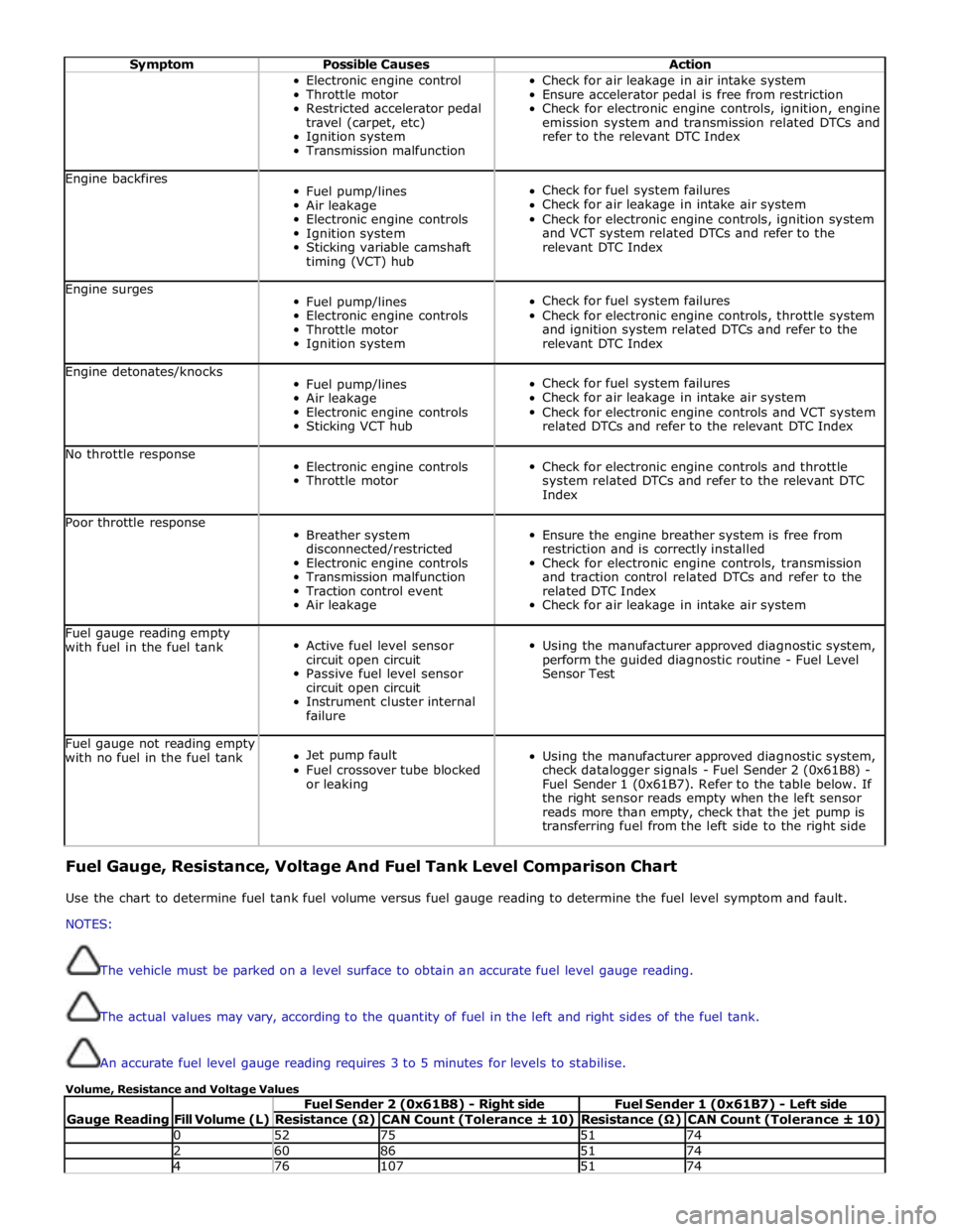
transferring fuel from the left side to the right side Fuel Gauge, Resistance, Voltage And Fuel Tank Level Comparison Chart
Use the chart to determine fuel tank fuel volume versus fuel gauge reading to determine the fuel level symptom and fault.
NOTES:
The vehicle must be parked on a level surface to obtain an accurate fuel level gauge reading.
The actual values may vary, according to the quantity of fuel in the left and right sides of the fuel tank.
An accurate fuel level gauge reading requires 3 to 5 minutes for levels to stabilise.
Volume, Resistance and Voltage Values
Gauge Reading
Fill Volume (L) Fuel Sender 2 (0x61B8) - Right side Fuel Sender 1 (0x61B7) - Left side Resistance (Ω) CAN Count (Tolerance ± 10) Resistance (Ω) CAN Count (Tolerance ± 10) 0 52 75 51 74 2 60 86 51 74 4 76 107 51 74
Page 1603 of 3039
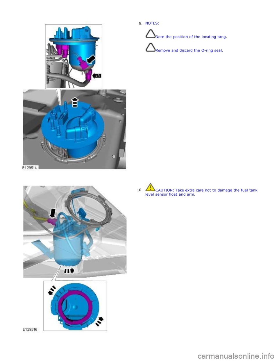
9.
10. NOTES:
Note the position of the locating tang.
Remove and discard the O-ring seal.
CAUTION: Take extra care not to damage the fuel tank
level sensor float and arm.
Page 1604 of 3039

Installation
1. CAUTIONS:
arm. Take extra care not to damage the fuel tank level sensor float and
Make sure the fuel pump and sender unit is correctly installed in to
the retaining bracket in the fuel tank.
NOTE: Make sure the locating tang is installed in the correct
position.
To install, reverse the removal procedure.
Page 1631 of 3039
Acceleration Control - Acceleration Control
Diagnosis and Testing
Principles of Operation Published: 11-May-2011
For a detailed description of the acceleration controls, refer to the relevant Description and Operation sections in the workshop
manual. REFER to: Acceleration Control (310-02, Description and Operation).
Inspection and Verification
CAUTION: Diagnosis by substitution from a donor vehicle is NOT acceptable. Substitution of control modules does not
guarantee confirmation of a fault, and may also cause additional faults in the vehicle being tested and/or the donor vehicle.
1. Verify the customer concern.
2. Visually inspect for obvious signs of damage and system integrity.
Visual Inspection
Mechanical Electrical
Accelerator pedal
Throttle body
Fuses
Wiring harness
Electrical connector(s)
Sensor(s)
Engine control module (ECM)
3. If an obvious cause for an observed or reported concern is found, correct the cause (if possible) before proceeding to
the next step.
4. If the cause is not visually evident check for Diagnostic Trouble Codes (DTCs) and refer to the DTC Index.
DTC Index
CAUTION: When probing connectors to take measurements in the course of the pinpoint tests, use the adaptor kit, part
number 3548-1358-00.
NOTES:
If the module or a component is suspect and the vehicle remains under the Manufacturers warranty, refer to the Warranty
Policy and Procedure manual (section B1.2), or determine if any prior approval programme is in operation, prior to the
installation of a new module/component.
Generic scan tools may not read the codes listed, or may read only five digit codes. Match the five digits from the scan
tool to the first five digits of the seven digit code listed to identify the fault (the last two digits give additional information
read by the manufacturer-approved diagnostic system).
When performing electrical voltage or resistance tests, always use a digital multimeter (DMM) accurate to three decimal
places, and with an up-to-date calibration certificate. When testing resistance, always take the resistance of the DMM leads
into account.
Check and rectify basic faults before beginning diagnostic routines involving pinpoint tests.
If DTCs are recorded and, after performing the pinpoint tests, a fault is not present, an intermittent concern may be the
cause. Always check for loose connections and corroded terminals.
DTC Description Possible Cause Action P012100 Throttle/Pedal
Position Sensor A
Circuit
Range/Performance
TP sensor sensing
circuits TP 1 and TP
2 - short to power,
high resistance
TP sensor failure Carry out any pinpoint tests associated with this DTC using the
manufacturer approved diagnostic system. Refer to the electrical
circuit diagrams and check TP sensor sensing circuits TP 1 and TP 2
for short to power, high resistance. Check and install a new throttle
body as required www.JagDocs.com
Page 1632 of 3039

DTC Description Possible Cause Action P012200 Throttle/Pedal
Position Sensor A
Circuit Low
TP sensor sensing
circuit TP 1 - short
to ground, high
resistance
TP sensor failure Carry out any pinpoint tests associated with this DTC using the
manufacturer approved diagnostic system. Refer to the electrical
circuit diagrams and check TP sensor sensing circuit TP 1 for short
to ground, high resistance. Check and install a new throttle body as
required P012300 Throttle/Pedal
Position Sensor A
Circuit High
TP sensor sensing
circuit TP1 - short
to power
TP sensor failure Carry out any pinpoint tests associated with this DTC using the
manufacturer approved diagnostic system. Refer to the electrical
circuit diagrams and check TP sensor sensing circuit TP 1 for short
to power. Check and install a new throttle body as required P022200 Throttle/Pedal
Position Sensor/Switch
B Circuit Low
TP sensor sensing
circuit TP 2 - short
to ground, high
resistance
TP sensor failure Carry out any pinpoint tests associated with this DTC using the
manufacturer approved diagnostic system. Refer to the electrical
circuit diagrams and check TP sensor sensing circuit TP 2 for short
to ground, high resistance. Check and install a new throttle body as
required P022300 Throttle/Pedal
Position Sensor/Switch
B Circuit High
TP sensor sensing
circuit TP 2- short
to power
TP sensor failure Carry out any pinpoint tests associated with this DTC using the
manufacturer approved diagnostic system. Refer to the electrical
circuit diagrams and check TP sensor sensing circuit TP 2 for short
to power. Check and install a new throttle body as required P022700 Throttle/Pedal
Position Sensor/Switch
C Circuit Low
APP sensor circuit
APP 1 - short to
ground, high
resistance Carry out any pinpoint tests associated with this DTC using the
manufacturer approved diagnostic system. Refer to the electrical
circuit diagrams and check APP sensor circuit APP 1 for short to
ground, high resistance P022800 Throttle/Pedal
Position Sensor/Switch
C Circuit High
APP sensor circuit
APP 1 - short to
power Carry out any pinpoint tests associated with this DTC using the
manufacturer approved diagnostic system. Refer to the electrical
circuit diagrams and check APP sensor circuit APP 1 for short to
power P210129 Throttle Actuator
Control Motor Circuit
Range/Performance
Signal invalid
Jammed throttle
blade, gearing or
motor Carry out any pinpoint tests associated with this DTC using the
manufacturer approved diagnostic system. Refer to the electrical
circuit diagrams and test throttle actuator control motor circuit for
short to ground, power, high resistance. Suspect the throttle body,
check and install a new throttle body as required, refer to the new module/component installation note at the top of the DTC Index P210162 Throttle Actuator
Control Motor Circuit
Range/Performance
Signal compare
failure
Jammed throttle
blade, gearing or
motor Carry out any pinpoint tests associated with this DTC using the
manufacturer approved diagnostic system. Refer to the electrical
circuit diagrams and test throttle actuator control motor circuit for
short to ground, power, high resistance. Suspect the throttle body,
check and install a new throttle body as required, refer to the new
module/component installation note at the top of the DTC Index P210164 Throttle Actuator
Control Motor Circuit
Range/Performance
Signal plausibility
failure
Jammed throttle
blade, gearing or
motor Carry out any pinpoint tests associated with this DTC using the
manufacturer approved diagnostic system. Refer to the electrical
circuit diagrams and test throttle actuator control motor circuit for
short to ground, power, high resistance. Suspect the throttle body,
check and install a new throttle body as required, refer to the new
module/component installation note at the top of the DTC Index P210177 Throttle Actuator
Control Motor Circuit
Range/Performance
Commanded
position not
achievable
Throttle blade
stuck open
Intake air system
leak Carry out any pinpoint tests associated with this DTC using the
manufacturer approved diagnostic system. Refer to the electrical
circuit diagrams and test throttle actuator control motor circuit for
short to ground, power, high resistance. Suspect the throttle body,
check and install a new throttle body as required, refer to the new
module/component installation note at the top of the DTC Index P210329 Throttle Actuator
Control Motor Circuit
High
Signal invalid
Throttle motor
control circuit -
short to power
ECM fault Carry out any pinpoint tests associated with this DTC using the
manufacturer approved diagnostic system. Refer to the electrical
circuit diagrams and check throttle motor control circuit for short to
power. If ECM is suspect, check and install a new module as
required, refer to new module/component installation note at top of
DTC Index P210364 Throttle Actuator
Control Motor Circuit
High
Signal plausibility
failure
Throttle motor
control circuit -
short to power Carry out any pinpoint tests associated with this DTC using the
manufacturer approved diagnostic system. Refer to the electrical
circuit diagrams and check throttle motor control circuit for short to
power. If ECM is suspect, check and install a new module as
required, refer to new module/component installation note at top of
DTC Index
Page 1633 of 3039

DTC Description Possible Cause Action ECM fault
P210500 Throttle Actuator
Control System -
Forced Engine
Shutdown
Throttle MIL
request due to fuel
cut Carry out any pinpoint tests associated with this DTC using the
manufacturer approved diagnostic system P211800 Throttle Actuator
Control Motor Current
Range/Performance
Throttle motor
control circuit -
short to ground,
power, high
resistance Carry out any pinpoint tests associated with this DTC using the
manufacturer approved diagnostic system. Refer to the electrical
circuit diagrams and check throttle motor control circuit for short to
ground, power, high resistance P211900 Throttle Actuator
Control Throttle Body
Range/Performance
Throttle spring
faulty Carry out any pinpoint tests associated with this DTC using the
manufacturer approved diagnostic system. Suspect throttle body
faulty. Check and install a new throttle body as required, refer to
the new module/component installation note at top of DTC Index P212200 Throttle/Pedal
Position Sensor/Switch
D Circuit Low
APP sensor circuit 2
- low input Carry out any pinpoint tests associated with this DTC using the
manufacturer approved diagnostic system. Refer to the electrical
circuit diagrams and check APP sensor circuit 2 for short to ground, open circuit P212216 Throttle/Pedal
Position Sensor/Switch
D Circuit Low Input
Accelerator pedal
position (APP)
sensor circuit 1 -
short to ground,
power
Accelerator pedal
position (APP)
sensor failure Carry out any pinpoint tests associated with this DTC using the
manufacturer approved diagnostic system. Refer to electrical circuit
diagrams and check accelerator pedal position (APP) sensor circuit 1
for short to ground, power. Set ignition status to 'ON' engine 'OFF'
check and record 'Pedal value sensor 1' datalogger signal. With
pedal in idle position, value of signal should be approximately 0%,
if not suspect the pedal position sensor, check and install a new
sensor as required P212300 Throttle/Pedal
Position Sensor/Switch
D Circuit High
APP sensor circuit 2
- high input Carry out any pinpoint tests associated with this DTC using the
manufacturer approved diagnostic system. Refer to the electrical
circuit diagrams and check APP sensor circuit 2 for short to power P212317 Throttle/Pedal
Position Sensor/Switch
D Circuit High Input
Accelerator pedal
position (APP)
sensor circuit 1 -
short to power
Accelerator pedal
position (APP)
sensor failure Carry out any pinpoint tests associated with this DTC using the
manufacturer approved diagnostic system. Refer to electrical circuit
diagrams and check accelerator pedal position (APP) sensor circuit 1
for short to ground, power. Set ignition status to 'ON' engine 'OFF'
check and record 'Pedal value sensor 1' datalogger signal. With
pedal in fully depressed position, value of signal should be
approximately 99%, if not suspect the pedal position sensor, check
and install a new sensor as required P212716 Throttle/Pedal
Position Sensor/Switch
E Circuit Low Input
Accelerator pedal
position (APP)
sensor circuit 2 -
short to ground,
high resistance
Accelerator pedal
position (APP)
sensor failure Carry out any pinpoint tests associated with this DTC using the
manufacturer approved diagnostic system. Refer to electrical circuit
diagrams and check accelerator pedal position (APP) sensor circuit 2
for short to ground, power. Set ignition status to 'ON' engine 'OFF'
check and record 'Pedal value sensor 2' datalogger signal. With
pedal in idle position, value of signal should be approximately 0%,
if not suspect the pedal position sensor, check and install a new
sensor as required P212817 Throttle/Pedal
Position Sensor/Switch
E Circuit High Input
Accelerator pedal
position (APP)
sensor circuit 2 -
short to power
Accelerator pedal
position (APP)
sensor failure Carry out any pinpoint tests associated with this DTC using the
manufacturer approved diagnostic system. Refer to electrical circuit
diagrams and check accelerator pedal position (APP) sensor circuit 2
for short to ground, power. Set ignition status to 'ON' engine 'OFF'
check and record 'Pedal value sensor 2' datalogger signal. With
pedal in fully depressed position, value of signal should be
approximately 99%, if not suspect the pedal position sensor, check
and install a new sensor as required P213528 Throttle/Pedal
Position Sensor/Switch
A/B Voltage
Correlation
APP sensor circuit 1
and 2 range
performance -
sub-processor Carry out any pinpoint tests associated with this DTC using the
manufacturer approved diagnostic system. Refer to the electrical
circuit diagrams and check APP sensor circuits 1 and 2 for short to
ground, power and high resistance. Clear the DTCs and retest. If
the code remains, replace the APP sensor P213529 Throttle/Pedal
Position Sensor/Switch
A/B Voltage
Correlation
APP sensor -
excessive difference
between
raw values of circuit
1 and 2 -
sub-processor Carry out any pinpoint tests associated with this DTC using the
manufacturer approved diagnostic system. Refer to the electrical
circuit diagrams and check APP sensor circuits 1 and 2 for short,
open circuit