sensor JAGUAR XFR 2010 1.G Workshop Manual
[x] Cancel search | Manufacturer: JAGUAR, Model Year: 2010, Model line: XFR, Model: JAGUAR XFR 2010 1.GPages: 3039, PDF Size: 58.49 MB
Page 1547 of 3039
Published: 28-Apr-2014
Exhaust System - V8 5.0L Petrol/V8 S/C 5.0L Petrol - Exhaust System - System Operation and Component Description
Description and Operation
CATALYTIC CONVERTERS System Operation
In the catalytic converters, the exhaust gases are passed through honeycombed ceramic elements coated with a special
surface treatment called 'washcoat'. The washcoat increases the surface area of the ceramic elements by a factor of
approximately 7000. On top of the washcoat is a coating containing palladium and rhodium, which are the active constituents
for converting harmful emissions into inert by-products. The palladium and rhodium add oxygen to the carbon monoxide and
the hydrocarbons in the exhaust gases, to convert them into carbon dioxide and water respectively.
SEMI-ACTIVE MUFFLER VALVE (5.0L SUPERCHARGER VEHICLES ONLY)
The semi-active muffler valve is operated by the pressure in the exhaust system. At low engine speeds the valve head is
closed or partially closed to provide a more refined noise quality. At higher engine speeds the increased pressure within the
exhaust system opens the valve head to provide a more sporting noise. This is achieved by the valve, which once open, allows
the exhaust gasses to by-pass the baffle tubes and plates in the rear silencer.
Component Description
FRONT SECTION - 4.2L NATURALLY ASPIRATED (NAS ONLY) - From 2010MY
The front section comprises two separate pipes, each incorporating a catalytic converter. Each catalytic converter has a welded
inlet pipe with a flange. The inlet pipe is flared into a cone which mates with the exhaust manifold. The flange has two holes
which locate on studs in the exhaust manifold and is secured with flanged nuts. Each catalytic converter is fitted with a pre
and post catalyst HO2S (heated oxygen sensor).
Each catalytic converter has a curved outlet pipe which mates with the respective inlet pipe for the applicable resonator on the
center section. The joint on each pipe is secured with a clamp.
FRONT SECTION - 5.0L NATURALLY ASPIRATED AND SUPERCHARGER - From 2010MY
The front section is common to both the naturally aspirated and supercharger vehicles. The front section comprises two
separate pipes each incorporating a catalytic converter. Each catalytic converter has a welded pipe with a flange, which is
flared into a cone which mates with the exhaust manifold. Each flange has two holes which locate on studs in the exhaust
manifold and are secured with nuts. Each catalytic converter is fitted with a mid catalyst HO2S. The mid catalyst HO2S is located in the catalytic converter.
NOTE: The pre catalyst HO2S is located in the exhaust manifold.
On vehicles from 2013MY, a post catalyst HO2S is located in the curved pipe from each catalytic converter.
A curved pipe from each catalytic converter locates into the resonator inlet pipes of the center section. The LH (left-hand) pipe
is fitted with a mass damper which absorbs resonance from the system.
REAR SECTION - 4.2L NATURALLY ASPIRATED (NAS ONLY) - From 2010MY
The 2 inlet pipes each connect into a separate resonator silencer. Each resonator silencer is cylindrical in shape and houses 2
perforated tubes separated by 2 baffle plates. Exhaust gasses exit each resonator silencer via an outlet pipe. The 2 outlet
pipes are joined together behind the resonators with a cross over pipe. Each pipe also has a welded hanger bracket which
allow the rear section to be supported on mounting rubbers. A further bracket is welded to each pipe which braces the 2 pipes
together.
The 2 rear silencers each have a welded inlet pipe which mate with the outlet pipes from the resonator silencers and are each
secured with a clamp. The inlet pipes each have a welded hanger bracket which support each rear silencer at the rear of the
vehicle on mounting rubbers. The fabricated rear silencers have 2 perforated tubes which are supported on 2 perforated baffle
plates. The exhaust gasses are expelled from the rear silencer via a single outlet pipe. The outlet pipe from each silencer has
a welded hanger bar which support the rear silencer on mounting rubbers. The outlet pipe is fitted with a welded outlet which
is covered with a polished stainless steel finisher which is part welded to the silencer.
REAR SECTION - 5.0L NATURALLY ASPIRATED - From 2010MY
The 2 pipes from the front section each connect into 2 short pipes on the center resonator box and are secured with clamps.
Two pipes from the resonator box split the system into 2 sections which each connect into another resonator. Each resonator
silencer houses perforated tubes separated by baffle plates. Exhaust gasses exit each resonator silencer via an outlet pipe.
The 2 outlet pipes are joined together behind the resonators with a cross over pipe. Each pipe also has a welded hanger
bracket which allow the rear section to be supported on mounting rubbers. A further bracket is welded to each pipe which
braces the 2 pipes together.
The 2 rear silencers each have a welded inlet pipe which mate with the outlet pipes from the cylindrical resonator silencers and
www.JagDocs.com
Page 1550 of 3039
Published: 11-May-2011
Exhaust System - V8 5.0L Petrol/V8 S/C 5.0L Petrol - Catalytic Converter LH
Removal and Installation
Removal
NOTE: Removal steps in this procedure may contain installation details.
1. Refer to: Battery Disconnect and Connect (414-01 Battery, Mounting and Cables, General Procedures).
2. WARNINGS:
Make sure to support the vehicle with axle stands.
Observe due care when working near a hot exhaust system.
Raise and support the vehicle.
3. Refer to: Air Deflector (501-02 Front End Body Panels, Removal and Installation).
4. Refer to: Engine Rear Undershield (501-02 Front End Body Panels, Removal and Installation).
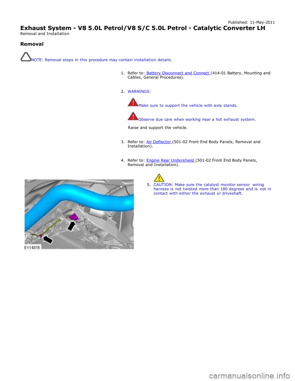
5. CAUTION: Make sure the catalyst monitor sensor wiring
harness is not twisted more than 180 degrees and is not in
contact with either the exhaust or driveshaft.
Page 1551 of 3039
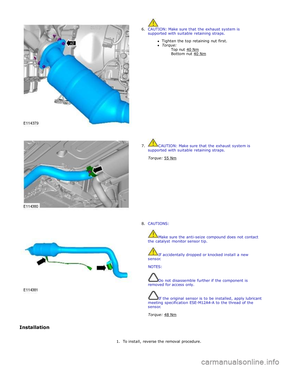
6. CAUTION: Make sure that the exhaust system is
supported with suitable retaining straps.
Tighten the top retaining nut first.
Torque:
Top nut 40 Nm Bottom nut 40 Nm
7. CAUTION: Make sure that the exhaust system is
supported with suitable retaining straps.
Torque: 55 Nm
8. CAUTIONS:
Make sure the anti-seize compound does not contact
the catalyst monitor sensor tip.
If accidentally dropped or knocked install a new
sensor.
NOTES:
Do not disassemble further if the component is
removed for access only.
If the original sensor is to be installed, apply lubricant
meeting specification ESE-M12A4-A to the thread of the
sensor.
Torque: 48 Nm
Installation
1. To install, reverse the removal procedure.
Page 1553 of 3039
Published: 11-May-2011
Exhaust System - V8 5.0L Petrol/V8 S/C 5.0L Petrol - Catalytic Converter RH
Removal and Installation
Removal
NOTE: Removal steps in this procedure may contain installation details.
1. Refer to: Battery Disconnect and Connect (414-01 Battery, Mounting and Cables, General Procedures).
2. WARNINGS:
Make sure to support the vehicle with axle stands.
Observe due care when working near a hot exhaust system.
Raise and support the vehicle.
3. Refer to: Air Deflector (501-02 Front End Body Panels, Removal and Installation).
4. Refer to: Engine Rear Undershield (501-02 Front End Body Panels, Removal and Installation).
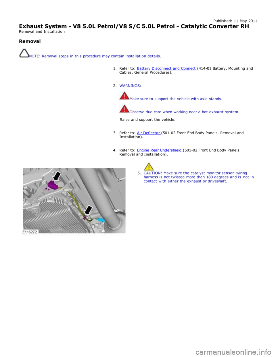
5. CAUTION: Make sure the catalyst monitor sensor wiring
harness is not twisted more than 180 degrees and is not in
contact with either the exhaust or driveshaft.
Page 1554 of 3039
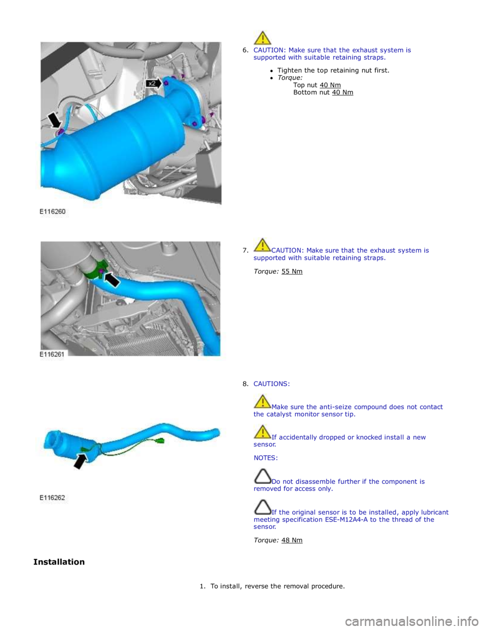
6. CAUTION: Make sure that the exhaust system is
supported with suitable retaining straps.
Tighten the top retaining nut first.
Torque:
Top nut 40 Nm Bottom nut 40 Nm
7. CAUTION: Make sure that the exhaust system is
supported with suitable retaining straps.
Torque: 55 Nm
8. CAUTIONS:
Make sure the anti-seize compound does not contact
the catalyst monitor sensor tip.
If accidentally dropped or knocked install a new
sensor.
NOTES:
Do not disassemble further if the component is
removed for access only.
If the original sensor is to be installed, apply lubricant
meeting specification ESE-M12A4-A to the thread of the
sensor.
Torque: 48 Nm
Installation
1. To install, reverse the removal procedure.
Page 1581 of 3039
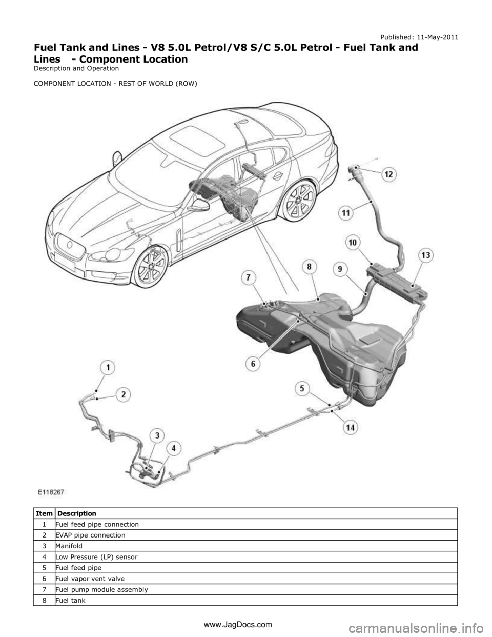
1 Fuel feed pipe connection 2 EVAP pipe connection 3 Manifold 4 Low Pressure (LP) sensor 5 Fuel feed pipe 6 Fuel vapor vent valve 7 Fuel pump module assembly 8 Fuel tank www.JagDocs.com
Page 1582 of 3039
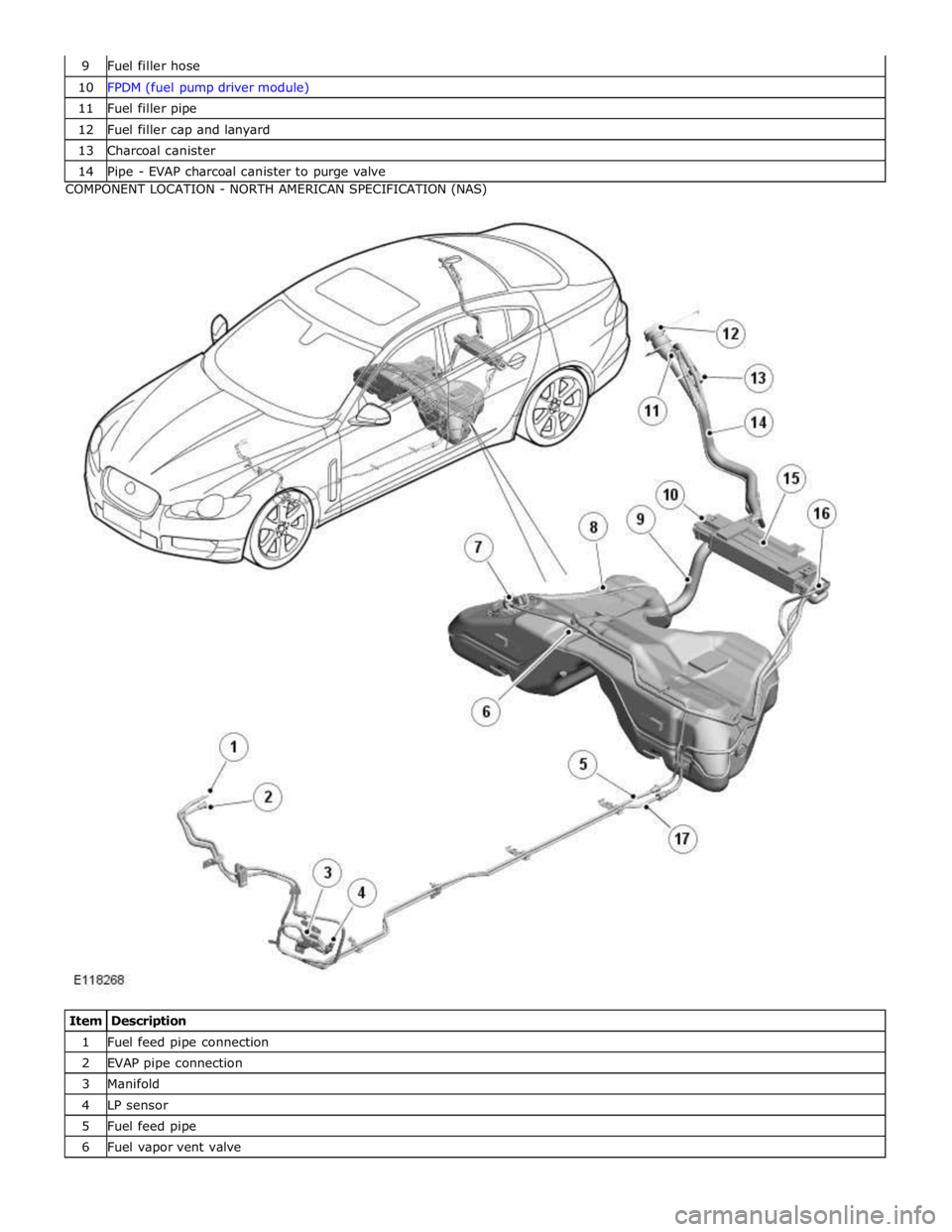
10 FPDM (fuel pump driver module) 11 Fuel filler pipe 12 Fuel filler cap and lanyard 13 Charcoal canister 14 Pipe - EVAP charcoal canister to purge valve COMPONENT LOCATION - NORTH AMERICAN SPECIFICATION (NAS)
Item Description 1 Fuel feed pipe connection 2 EVAP pipe connection 3 Manifold 4 LP sensor 5 Fuel feed pipe 6 Fuel vapor vent valve
Page 1584 of 3039
the flow and pressure supplied by controlling the operation of the fuel pump using a PWM (pulse width modulation) output. A
LP sensor is located in the fuel feed supply line to the engine and is monitored by the ECM for fuel pump control.
Two fuel level sensors are installed in either side of the saddle tank. The sensors are a MAPPS (magnetic passive position
sensor) which provide a variable resistance to ground for the output from the fuel gage.
The fuel system also incorporates an EVAP (evaporative emission) system which is part of the on-board refueling and vapor
recovery feature. The function and operation of the system is designed to meet EVAP requirements to minimize fuel vapor losses.
Page 1586 of 3039
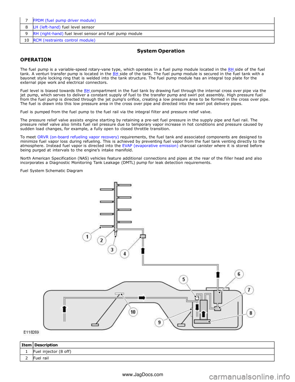
8 LH (left-hand) fuel level sensor 9 RH (right-hand) fuel level sensor and fuel pump module 10 RCM (restraints control module)
OPERATION System Operation
The fuel pump is a variable-speed rotary-vane type, which operates in a fuel pump module located in the RH side of the fuel tank. A venturi transfer pump is located in the RH side of the tank. The fuel pump module is secured in the fuel tank with a bayonet style locking ring that is welded into the tank structure. The fuel pump module has an integral top plate for the
external pipe work and electrical connectors.
Fuel level is biased towards the RH compartment in the fuel tank by drawing fuel through the internal cross over pipe via the jet pump, which serves to deliver a constant supply of fuel to the transfer pump and swirl pot assembly. High pressure fuel
from the fuel pump is directed through the jet pump's orifice, creating a low pressure area to be formed in the cross over pipe.
The fuel is drawn into this low pressure area in the cross over pipe and directed into the swirl pot delivery pipes.
Fuel is pumped from the fuel pump to the fuel rail via the integral filter and pressure relief valve.
The pressure relief valve assists engine starting by retaining a pre-set fuel pressure in the supply pipe and fuel rail. The
pressure relief valve also limits fuel rail pressure due to temporary vapor increase in hot conditions and pressure caused by
sudden load changes, for example, a fully open to closed throttle transition.
To meet ORVR (on-board refueling vapor recovery) requirements, the fuel tank and associated components are designed to
minimize fuel vapor loss during refueling. This is achieved by preventing fuel vapor from the fuel tank venting directly to the
atmosphere. Instead fuel vapor is directed into the EVAP (evaporative emission) charcoal canister where it is stored before
being purged at intervals to the engine’s intake manifold.
North American Specification (NAS) vehicles feature additional connections and pipes at the rear of the filler head and also
incorporates a Diagnostic Monitoring Tank Leakage (DMTL) pump for leak detection requirements.
Fuel System Schematic Diagram
Item Description 1 Fuel injector (8 off) 2 Fuel rail www.JagDocs.com
Page 1587 of 3039
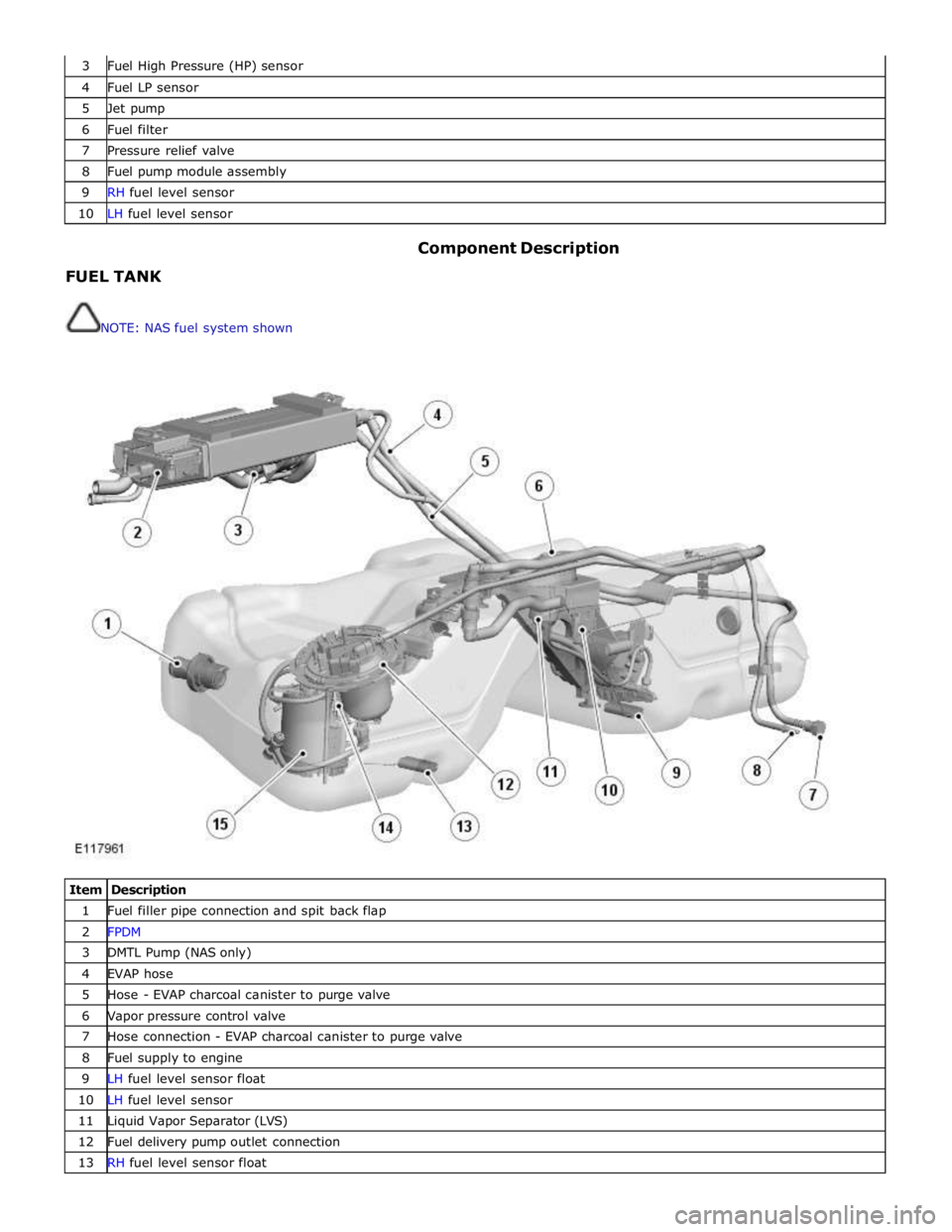
3 Fuel High Pressure (HP) sensor 4 Fuel LP sensor 5 Jet pump 6 Fuel filter 7 Pressure relief valve 8 Fuel pump module assembly 9 RH fuel level sensor 10 LH fuel level sensor
FUEL TANK
NOTE: NAS fuel system shown Component Description
Item Description 1 Fuel filler pipe connection and spit back flap 2 FPDM 3 DMTL Pump (NAS only) 4 EVAP hose 5 Hose - EVAP charcoal canister to purge valve 6 Vapor pressure control valve 7 Hose connection - EVAP charcoal canister to purge valve 8 Fuel supply to engine 9 LH fuel level sensor float 10 LH fuel level sensor 11 Liquid Vapor Separator (LVS) 12 Fuel delivery pump outlet connection 13 RH fuel level sensor float