Dtc JAGUAR XFR 2010 1.G Workshop Manual
[x] Cancel search | Manufacturer: JAGUAR, Model Year: 2010, Model line: XFR, Model: JAGUAR XFR 2010 1.GPages: 3039, PDF Size: 58.49 MB
Page 1856 of 3039
Parking Aid - Proximity Camera
Diagnosis and Testing
Principles of Operation Published: 30-Apr-2014
For a detailed description of the rear view camera system, refer to the relevant Description and Operation section of the
workshop manual.
Inspection and Verification
CAUTION: Diagnosis by substitution from a donor vehicle is NOT acceptable. Substitution of control modules does not
guarantee confirmation of a fault, and may also cause additional faults in the vehicle being tested and/or the donor vehicle.
NOTES:
If a control module or a component is suspect and the vehicle remains under manufacturer warranty, refer to the Warranty
Policy and Procedures manual, or determine if any prior approval programme is in operation, prior to the installation of a new
module/component.
When performing voltage or resistance tests, always use a digital multimeter accurate to three decimal places, and with
an up-to-date calibration certificate. When testing resistance always take the resistance of the digital multimeter leads into
account.
Check and rectify basic faults before beginning diagnostic routines involving pinpoint tests.
1. Verify the customer concern
2. Visually inspect for obvious signs of damage and system integrity
Visual Inspection
Mechanical Electrical
Touch screen
Rear view camera
Fuses
Wiring harnesses and connectors
Touch screen
Rear view camera
3. If an obvious cause for an observed or reported concern is found, correct the cause (if possible) before proceeding to
the next step
4. If the cause is not visually evident, verify the symptom and refer to the Symptom Chart, alternatively check for
Diagnostic Trouble Codes (DTCs) and refer to the DTC Index
5. Check DDW for open campaigns. Refer to the corresponding bulletins and SSMs which may be valid for the specific
customer complaint and carry out the recommendations as required
Symptom Chart
Symptom Possible Cause Action Rear view camera
image slow to react
System operation within
specification
NOTE: After selecting reverse, it may take up to 20 seconds for the
image to be displayed.
No further action necessary Blank screen
Rear view camera not
functioning
GO to Pinpoint Test A. Blue screen
Video in signal absent
GO to Pinpoint Test B. No tracking lines
Missing/invalid reverse
gear signal
LIN fault
Using the manufacturer approved diagnostic system, check the
central junction box for related DTCs and refer to the relevant
DTC index
GO to Pinpoint Test C.
Page 1858 of 3039

NOTE: The vehicle may take 30 seconds (or 100m) to learn the steering centre position after starting the engine. This is
normal. 1 Start the engine 2 Wait at least 30 seconds 3 Select reverse gear 4 Turn the steering wheel and observe the touch screen Do the tracking lines react to steering input? Yes
No fault present
No
Potential LIN data gateway fault DTC Index
For a list of Diagnostic Trouble Codes (DTCs) that could be logged on this vehicle, please refer to Section 100-00.
Page 1878 of 3039
Battery, Mounting and Cables - Battery and Cables - Overview
Description and Operation
OVERVIEW
Single Battery Vehicles Published: 18-Jun-2014
Mounted on the battery negative terminal is a BMS (battery monitoring system) module. The BMS module is integral with the
battery negative cable and is controlled by the ECM (engine control module).
CAUTION: To avoid damaging the battery monitoring system module, always use a suitable body ground point rather than
the battery negative terminal when connecting a slave power supply to the vehicle.
If a new battery is fitted to the vehicle, the BMS module will require re-calibrating using the Jaguar approved diagnostic
system.
Fitted on the battery positive terminal is a transit relay. The transit relay must be removed from the vehicle during the
Pre-Delivery Inspection (PDI). For additional information, refer to the PDI Manual.
The vehicle battery provides power to the BJB (battery junction box). The BJB contains 3 megafuses, delivering power to the RJB (rear junction box), the CJB (central junction box) and the EJB (engine junction box). In addition to containing fuses and
relays, the RJB and RJB contain software to control a number of vehicle systems. These functions are covered in the appropriate sections of this manual.
Dual Battery System Vehicles - TD42.2L Engine Variants Only
Two batteries are fitted to accommodate the dual battery system used for the Stop/Start system.
A primary battery is located in the luggage compartment floor in a plastic molded tray and secured with a metal rod. The
secondary battery is located in the DBJB (dual battery junction box).
The primary battery is a 90Ahr, 850A CCA AGM Battery.
The secondary battery is a 14Ahr, 200A CCA Absorbed Glass Mat (AGM) Battery.
A BMS (battery monitoring system) control module is mounted on the primary battery negative terminal. The BMS control
module is integral with the battery negative cable and is controlled by the GWM (gateway module).
CAUTION: To avoid damaging the BMS control module, always use the ground (negative (-)) terminal stud point on the
right side top mount. Never connect directly to the primary battery negative terminal when connecting a slave power supply to
the vehicle, the BMS control module can be damaged.
If a new primary battery is fitted to the vehicle, the BMS control module will require re-calibrating using a Jaguar approved
diagnostic system.
When the vehicle leaves the factory, a transit relay is fitted to the battery positive terminal. The transit relay is connected to
the CJB which limits the electrical functions to essential items only, to reduce loads on the primary battery. The transit relay must be removed from the vehicle during the PDI (Pre-Delivery Inspection). For additional information, refer to the PDI.
The primary battery provides power to the BJB. The BJB contains three megafuses, delivering power to the RJB, the EJB and the starter motor and generator. In addition to containing fuses and relays, the RJB and CJB contain software to control a number of vehicle systems. These functions are covered in the appropriate sections of this manual.
A jump start terminal is located adjacent to the EJB. A cover protects the terminal when not in use. If jump starting is
required, the cover must be removed and the positive (+) jump lead attached securely. The negative (-) jump lead is attached
to a stud located on the right side top mount in the engine compartment. The cover must be fitted to the positive terminal
when not in use.
Dual Battery System
The dual battery system is used on vehicles with the stop/start system. The dual battery system prevents the vehicle
electrical systems being subjected to undesirably low voltages during repeated engine restarts. If the electrical systems are
subject to low voltages the customer may notice degraded performance of components and systems and incorrect fault DTC
(diagnostic trouble code)'s may be stored.
The dual battery system isolates all electrical components and systems sensitive to low supply voltage from the primary
battery while an engine start is in progress, and supplies them from the secondary battery. Without the dual battery system,
the electrical power required by the TSS (Tandem Solenoid Starter) motor to crank the engine for each start would cause a
voltage drop across the entire vehicle electrical network, and cause control modules to function incorrectly and in some cases
reset and/or record DTC's.
If the dual battery system is unable to prevent electrical supplies to the vehicle systems being subjected to low voltage levels
during engine stop/start operations, due to the condition of the primary and/or secondary batteries or a system fault, the
stop/start feature is disabled.
Page 1879 of 3039

The dual battery system comprises the following components:
Dual Battery Module (DBM).
Dual Battery Junction Box (DBJB).
Gateway Module (GWM).
Primary battery.
Secondary battery.
The GWM hosts most of the software required to control the dual battery system and components. The GWM monitors the
components and can store fault related DTC's.
The GWM also controls the charging system software in conjunction with the ECM, RJB, CJB and ABS (anti-lock brake system) control module via the high speed and medium speed CAN (controller area network) bus. The GWM software will monitor the
status of the stop/start system and determine when a stop/start event can occur. It can also intervene to maintain vehicle
systems by keeping the engine running or initiating a restart due to, for example, climate control system requirements or
request for restart from the ECM. A brake pressure signal is received from the ABS control module which will indicate to the
GWM that an engine restart is required from driver operation of the foot brake.
The GWM contains the intelligent power management system and the BMS software. Monitoring of the primary battery
condition for stop/start is controlled by the GWM and the BMS control module.
Page 1885 of 3039

is operated to crank the engine. The GWM is connected to the ABS (Anti-lock Brake System) control module via the high speed
CAN bus. With the vehicle stationary and the engine off after an ECO engine stop, when the driver releases the brake pedal
the ABS control module senses the reduction in brake pressure. This change of brake pressure state is sent as a high speed
CAN message which is received by the GWM and the ECM. The GWM reacts within 105ms to instruct the DBM via the LIN bus
to operate the two contactors in the DBJB to supply the sensitive loads from the secondary battery and supply the TSS motor
direct from the primary battery.
When the engine is running and the generator is supplying power to the vehicle systems, the GWM again instructs the DBM to
operate the two contactors in the DBJB to supply all vehicle systems from the primary battery and the generator and to isolate
the secondary battery.
Secondary Battery Charging
The DBM also controls the charging of the secondary battery. The GWM contains electrical load management software and
monitors both batteries for their state of charge. The primary battery is monitored by the BMS control module which is
connected to the DBM via the LIN bus. The DBM communicates the primary battery condition to the GWM via a LIN bus
connection. The GWM sends a signal to the DBM via the LIN bus to instruct it to apply charging from the generator to the
secondary battery when required. The contactor 2 is closed by the DBJB to complete the secondary battery circuit, and the
generator output is applied to the secondary battery to charge it.
The generator output is controlled by the GWM which monitors and controls the electrical load management system. The
generator is connected to the GWM by a LIN bus allowing the GWM to control the output of the generator to maintain electrical
system load requirements and battery charging.
Electrical Load Management
The electrical load management is controlled by the GWM and the BMS control module.
The GWM will monitor the vehicle system power loads before and during an ECO engine stop.
Before an ECO engine stop, the GWM will transmit a signal to system control modules on the CAN bus to request a power save
on all electrical loads and set a minimum electrical value override. The GWM monitors the vehicle electrical loads and will
inhibit a ECO engine stop until the load current is at a value low enough to be supported by the secondary battery.
If the electrical loads cannot be reduced sufficiently, the GWM will inhibit the ECO engine stop.
When the engine is stopped after an ECO engine stop, the GWM will continue to monitor the primary battery state of charge.
If the primary or secondary battery voltage falls below 11.0V, a level which will result in degraded starting performance or
possible primary battery damage, the GWM will initiate an engine start.
System Inhibits
The ECO stop/start system is inhibited if the dual battery system is not be capable of preventing electrical loads on the
vehicle being subject to unacceptably low voltage levels during ECO stop/start operations due to a fault.
ECO stop/start inhibit monitoring of the primary battery is performed by the BMS control module. If the primary battery voltage
is too low to support an ECO stop/start, then the BMS control module will send a message to the GWM on the LIN bus to
suspend ECO stop/start.
The GWM monitors the secondary battery and the dual battery system components. Any fault found will cause the GWM to
inhibit ECO stop/start and the GWM will record a DTC (diagnostic trouble code).
Fault Diagnosis
The GWM performs passive and active diagnostics on the dual battery system to determine the status of the system
components.
Passive diagnostics can detect faults in the DBJB and can check for stuck open or closed contactors and failure of DBM
contactor command signals.
Active diagnostics is a routine to test the capability of the contactors to respond to open or close command signals sent from
the GWM to the DBM. This routine also checks the FET's (Field Effect Transistors) activate as required. (Refer to Dual Battery
Junction Box below for description of FET operation)
The GWM will also check the dual battery system components for faults in a controlled environment when the generator is
providing a charging output. This will ensure that the detection of a fault will not result in sensitive electrical loads being
subjected to low voltage which may occur during an ECO stop/start with a fault present.
The GWM will illuminate the charge warning indicator in the instrument cluster if fault is detected in the dual battery system
which will result in a degraded power supply.
If a fault is detected the GWM transmits a CAN message to inhibit ECO stop/start operation. In some cases it will record a
DTC, display a warning message in instrument cluster and also illuminate charge warning indicator.
PRIMARY BATTERY - ALL VEHICLES Component Description
The primary battery is located in a plastic tray under the luggage compartment floor in the right side of the luggage
compartment, adjacent to the spare wheel. The battery is vented via a tube which is connected with a T piece to the vent from
Page 1886 of 3039
the secondary battery (if fitted) and passes through a grommet in the floorpan.
On new vehicles the primary battery positive terminal is fitted with a transit relay. The transit relay must removed using the
correct process detailed in the Pre Delivery Inspection (PDI) manual.
The battery negative terminal is fitted with a BMS control module. The control module is integral with the battery negative
cable and communicates with the GWM via a LIN bus connection. The battery condition information is passed to the GWM
which controls the generator output accordingly.
CAUTION: To avoid damage to the BMS control module, always use the body ground point in the engine compartment and
not the battery negative terminal when connecting a slave power supply.
Failure to use the recommended ground point will lead to the setting of a DTC. Incorrect information of battery condition will
be retained by the BMS control module due to the unmonitored current flow into the battery. The system will however,
recognize and compensate for the change in battery status after a period of time.
If a new battery is fitted, the BMS control module will require re-calibration using a Jaguar approved diagnostic system.
Replacement of the BMS control module requires no action as the control module will re-calibrate automatically.
SECONDARY BATTERY - DUAL BATTERY VEHICLES ONLY
The secondary battery is located in a tray on the next of the primary battery and is secured to the DBJB with a bracket. The
battery negative (-) terminal is connected via a cable to the vehicle body. The positive (+) terminal is connected by a cable to
the DBJB. The battery is vented via a tube which is connected with a T piece to the vent from the primary battery and passes
through a grommet in the floorpan.
The state of charge of the secondary battery is monitored by the Gateway Module (GWM).
BATTERY MONITORING SYSTEM (BMS)
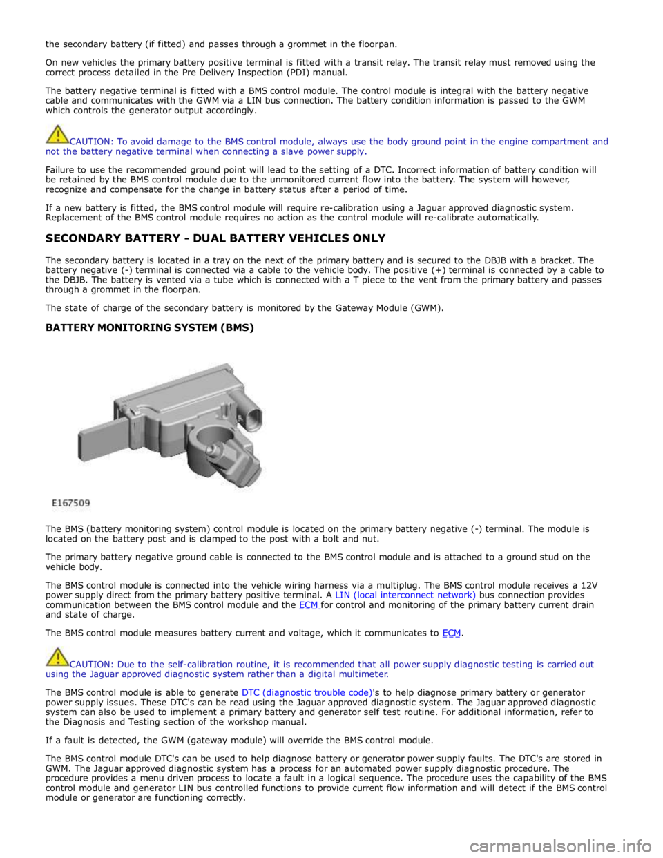
The BMS (battery monitoring system) control module is located on the primary battery negative (-) terminal. The module is
located on the battery post and is clamped to the post with a bolt and nut.
The primary battery negative ground cable is connected to the BMS control module and is attached to a ground stud on the
vehicle body.
The BMS control module is connected into the vehicle wiring harness via a multiplug. The BMS control module receives a 12V
power supply direct from the primary battery positive terminal. A LIN (local interconnect network) bus connection provides
communication between the BMS control module and the ECM for control and monitoring of the primary battery current drain and state of charge.
The BMS control module measures battery current and voltage, which it communicates to ECM.
CAUTION: Due to the self-calibration routine, it is recommended that all power supply diagnostic testing is carried out
using the Jaguar approved diagnostic system rather than a digital multimeter.
The BMS control module is able to generate DTC (diagnostic trouble code)'s to help diagnose primary battery or generator
power supply issues. These DTC's can be read using the Jaguar approved diagnostic system. The Jaguar approved diagnostic
system can also be used to implement a primary battery and generator self test routine. For additional information, refer to
the Diagnosis and Testing section of the workshop manual.
If a fault is detected, the GWM (gateway module) will override the BMS control module.
The BMS control module DTC's can be used to help diagnose battery or generator power supply faults. The DTC's are stored in
GWM. The Jaguar approved diagnostic system has a process for an automated power supply diagnostic procedure. The
procedure provides a menu driven process to locate a fault in a logical sequence. The procedure uses the capability of the BMS
control module and generator LIN bus controlled functions to provide current flow information and will detect if the BMS control
module or generator are functioning correctly.
Page 1889 of 3039
Battery, Mounting and Cables - Battery
Diagnosis and Testing
Principles of Operation Published: 10-Mar-2014
For a detailed description of the battery system and operation, refer to the relevant Description and Operation section of the
workshop manual. REFER to: Battery and Cables (414-01 Battery, Mounting and Cables, Description and Operation).
Inspection and Verification
CAUTION: Diagnosis by substitution from a donor vehicle is NOT acceptable. Substitution of control modules does not
guarantee confirmation of a fault and may also cause additional faults in the vehicle being checked and/or the donor vehicle.
NOTES:
Generic scan tools may not read the codes listed, or may read only five digit codes. Match the five digits from the scan
tool to the first five digits of the seven digit code listed to identify the fault (the last two digits give additional information
read by the manufacturer-approved diagnostic system).
When performing electrical voltage or resistance tests, always use a digital multimeter (DMM) accurate to three decimal
places, and with an up-to-date calibration certificate. When testing resistance, always take the resistance of the DMM leads
into account.
Check and rectify basic faults before beginning diagnostic routines involving pinpoint tests.
If DTCs are recorded and, after performing the pinpoint tests, a fault is not present, an intermittent concern may be the
cause. Always check for loose connections and corroded terminals.
1. Verify the customer concern.
2. Visually inspect for obvious signs of mechanical or electrical damage.
Visual Inspection
Mechanical Electrical
Generator
Drive belt
Drive belt tensioner
Generator pulley
Check the security of the generator fixings
Generator
Battery
Battery connections
Starter motor
Harnesses and connectors
Fuses
Charge warning lamp function
Engine Control Module (ECM)
3. If an obvious cause for an observed or reported concern is found, correct the cause (if possible) before proceeding to
the next step.
4. If the cause is not visually evident check for Diagnostic Trouble Codes (DTCs) and refer to the DTC Index.
5. Check DDW for open campaigns. Refer to the corresponding bulletins and SSMs which may be valid for the specific
customer complaint and carry out the recommendations as required
Symptom Chart
Symptom Possible Causes Action
Battery power to vehicle
interrupted
High resistance between battery terminals and
clamps
GO to Pinpoint Test
A. Midtronics EXP-1080 User Guide
Carry out the following: -
Surface Voltage Removal Process
A vehicle which has had its battery charged or been driven in a 24 hour period before the test, must have its surface charge
removed
Page 1899 of 3039
Battery
test
code,
must
be
given if
a
battery,
starter
motor
or
generator
is
exchanged
under
warranty
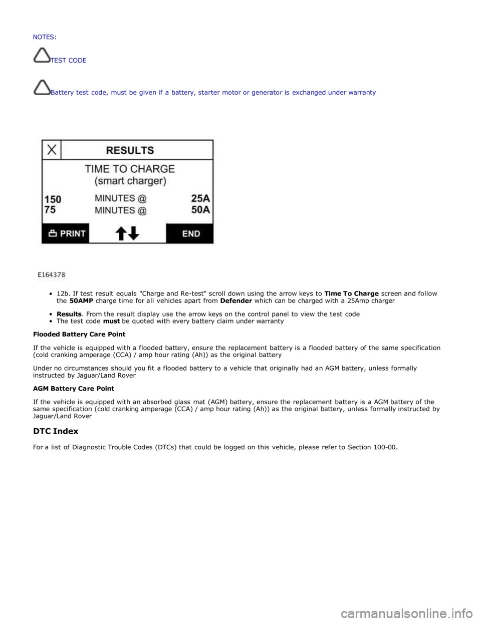
12b.
If
test
result
equals
"Charge
and
Re-test"
scroll
down
using
the
arrow
keys
to
Time To
Charge
screen and follow
the
50AMP
charge
time
for
all
vehicles
apart
from
Defender
which
can
be
charged
with a
25Amp
charger
Results.
From
the
result
display
use
the
arrow
keys
on
the
control
panel
to
view the
test
code
The
test
code
must
be
quoted
with every
battery
claim
under
warranty
Flooded
Battery
Care
Point
If
the
vehicle
is
equipped with
a
flooded
battery,
ensure
the
replacement
battery
is
a
flooded
battery
of
the
same
specification
(cold
cranking
amperage
(CCA)
/ amp
hour
rating
(Ah))
as
the
original
battery
Under
no
circumstances
should you
fit
a
flooded
battery
to a
vehicle
that
originally
had
an
AGM
battery,
unless
formally
instructed
by Jaguar/Land
Rover
AGM
Battery
Care
Point
If
the
vehicle
is
equipped with
an absorbed
glass
mat
(AGM)
battery,
ensure
the
replacement
battery
is
a
AGM
battery
of
the
same
specification
(cold
cranking
amperage
(CCA)
/
amp
hour
rating
(Ah))
as
the
original
battery,
unless
formally
instructed
by
Jaguar/Land
Rover
DTC
Index
For
a
list
of
Diagnostic
Trouble
Codes
(DTCs)
that
could
be
logged
on
this
vehicle,
please
refer
to
Section
100-00. NOTES:
TESTCODE
Page 1932 of 3039
Published: 11-Jul-2014
Information and Entertainment System - General Information - Information
and Entertainment System
Diagnosis and Testing
Principle of Operation
For a detailed description of the Information and Entertainment System, refer to the relevant Description and Operation
sections in the workshop manual. REFER to: (415-01A Information and Entertainment System)
Audio System (Description and Operation), Audio System (Description and Operation), Audio System (Description and Operation).
Inspection and Verification
CAUTION: Diagnosis by substitution from a donor vehicle is NOT acceptable. Substitution of control modules does not
guarantee confirmation of a fault, and may also cause additional faults in the vehicle being tested and/or the donor vehicle.
1. Verify the customer concern.
2. Visually inspect for obvious signs of damage and system integrity.
Visual Inspection
Mechanical Electrical
Information and entertainment module
Audio amplifier module
Integrated audio module
Portable audio interface module
Digital audio broadcast module
Integrated control panel
Touch screen display
Satellite radio module
Television module
Navigation system module
Telephone module
Compact disc player jammed, not loading
Scratched/dirty compact discs
Speakers
Fuses
Loose or corroded connector(s)
Information and entertainment module
Audio amplifier module
Integrated audio module
Portable audio interface module
Digital audio broadcast module
Integrated control panel
Touch screen display
Satellite radio module
Television module
Navigation system module
Telephone module
Speakers
3. If an obvious cause for an observed or reported concern is found, correct the cause (if possible) before proceeding to
the next step.
4. If the cause is not visually evident, check for Diagnostic Trouble Codes (DTCs) and refer to the relevant DTC Index.
Symptom Chart
Symptom Display Possible Causes Action Poor audio quality (all
sources) Display normal
MOST harness
connections loose
MOST harness
connections
contaminated
MOST harness
misrouted
- Too many
bends
- Bend radius
less than
25mm
Check MOST harness connectors for
security
Check MOST harness connectors for
contamination
Check the routing of the MOST harness Information and
entertainment system
inoperative Touch screen blank or
displaying a flashing
logo
MOST network fault
REFER to: Communications Network (418-00 Module Communications Network,
Diagnosis and Testing).
DTC Index
For a list of Diagnostic Trouble Codes (DTCs) that could be logged on this vehicle, please refer to Section 100-00. REFER to:
(100-00 General Information)
Page 1933 of 3039

Diagnostic Trouble Code (DTC) Index - DTC: Integrated Audio Module (IAM) (Description and Operation), Diagnostic Trouble Code (DTC) Index - DTC: Infotainment Control Module (ICM) (Description and Operation), Diagnostic Trouble Code (DTC) Index - DTC: Integrated Control Panel (FCIMB) (Description and Operation), Diagnostic Trouble Code (DTC) Index - DTC: Satellite Digital Audio Radio System Module (SARM) (Description and Operation), Diagnostic Trouble Code (DTC) Index - DTC: Digital Audio Broadcast Module (DABM) (Description and Operation), Diagnostic Trouble Code (DTC) Index - DTC: Hybrid Digital Radio Control Module (HDRCM) (Description and Operation), Diagnostic Trouble Code (DTC) Index - DTC: Touch Screen Display (FCDIM) (Description and Operation), Diagnostic Trouble Code (DTC) Index - DTC: Television Module (TVM) (Description and Operation), Diagnostic Trouble Code (DTC) Index - DTC: Portable Audio Interface Control Module (PAICM) (Description and Operation).