JAGUAR XFR 2010 1.G Workshop Manual
XFR 2010 1.G
JAGUAR
JAGUAR
https://www.carmanualsonline.info/img/21/7642/w960_7642-0.png
JAGUAR XFR 2010 1.G Workshop Manual
Trending: roof rack, B102, instrument panel, torque, fuse diagram, b1081, 206-04B
Page 371 of 3039
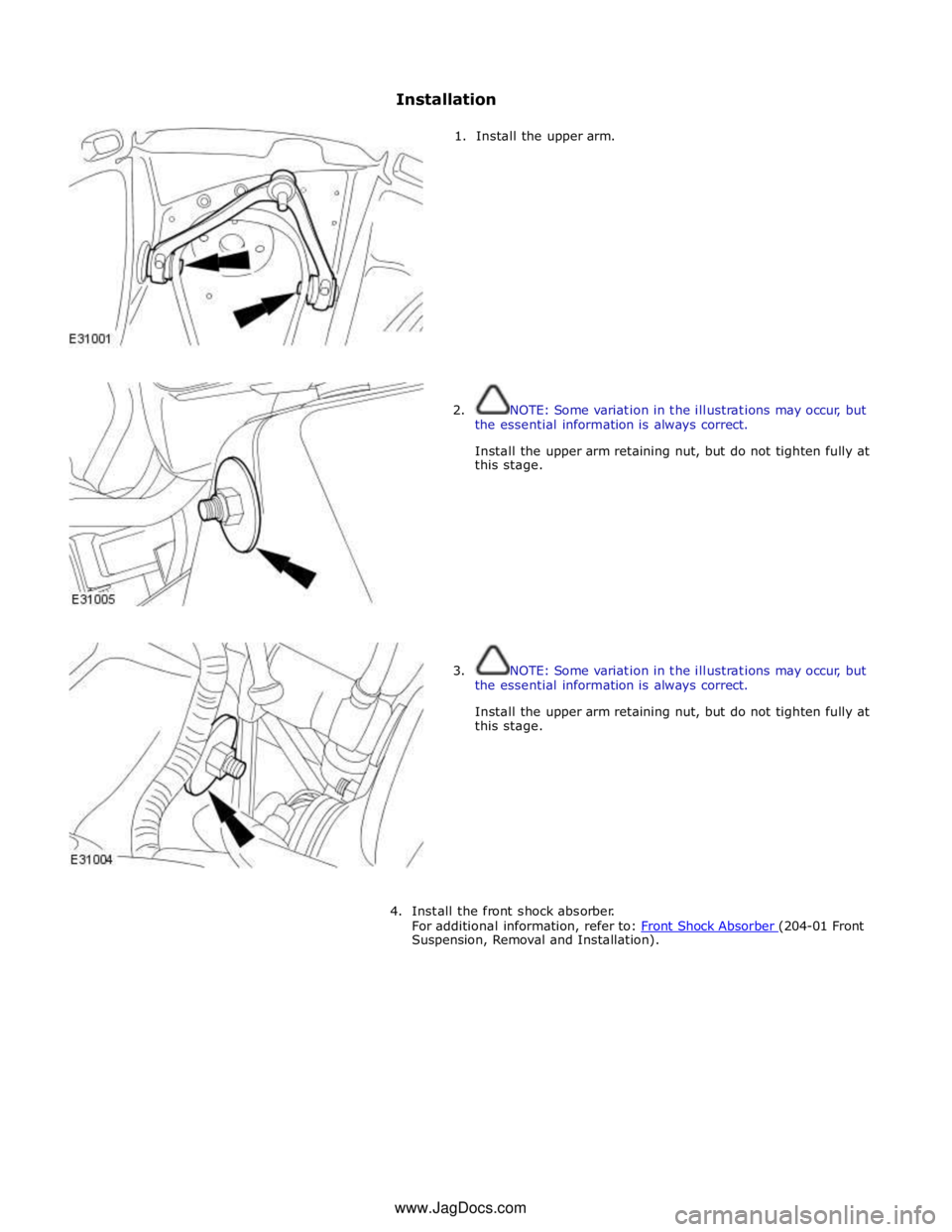
Suspension, Removal and Installation). www.JagDocs.com
Page 372 of 3039
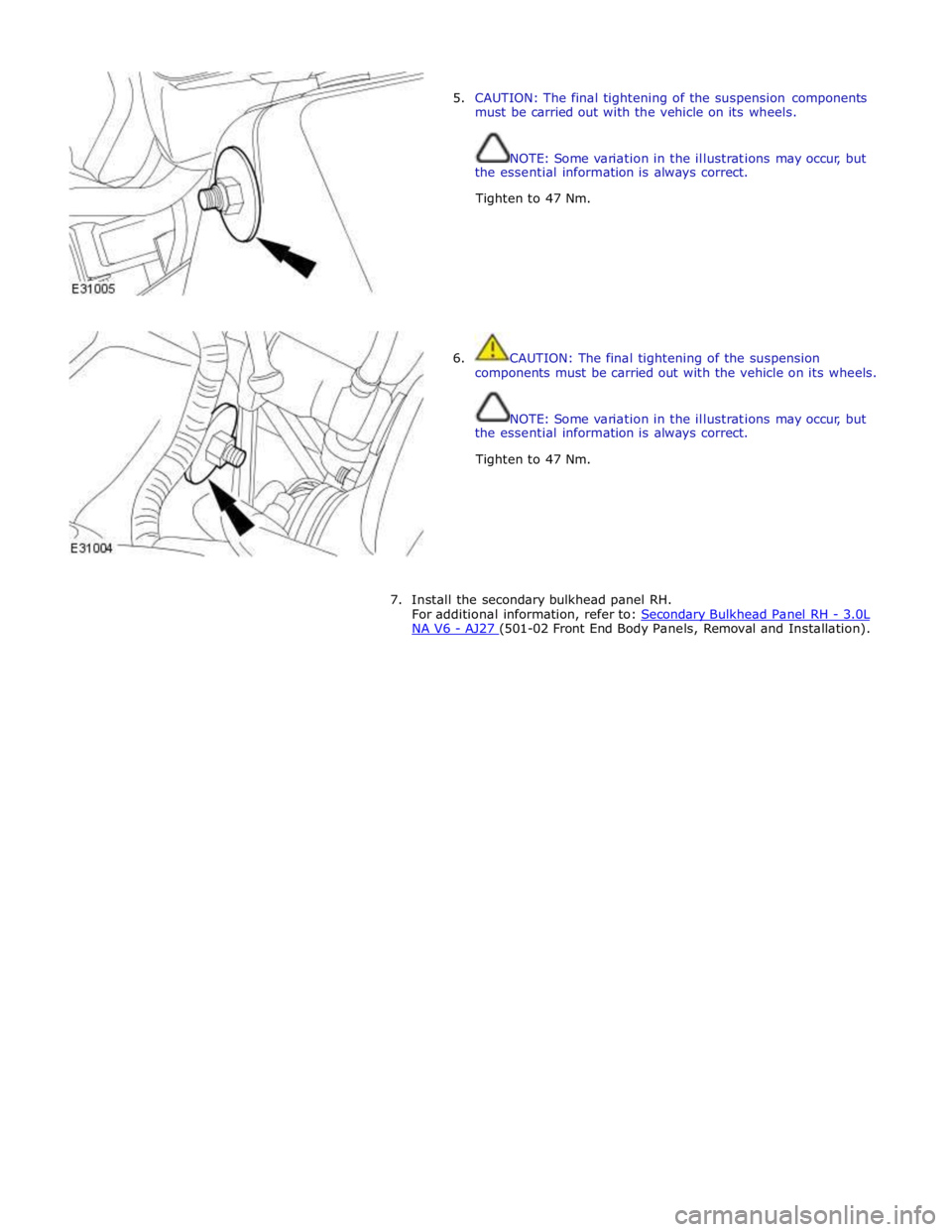
5. CAUTION: The final tightening of the suspension components
must be carried out with the vehicle on its wheels.
NOTE: Some variation in the illustrations may occur, but
the essential information is always correct.
Tighten to 47 Nm.
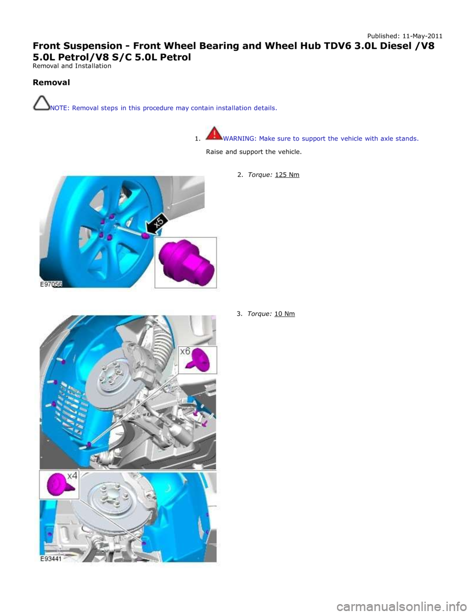
6. CAUTION: The final tightening of the suspension
components must be carried out with the vehicle on its wheels.
NOTE: Some variation in the illustrations may occur, but
the essential information is always correct.
Tighten to 47 Nm.
7. Install the secondary bulkhead panel RH.
For additional information, refer to: Secondary Bulkhead Panel RH - 3.0L NA V6 - AJ27 (501-02 Front End Body Panels, Removal and Installation).
Page 373 of 3039
Published: 11-May-2011
Front Suspension - Front Wheel Bearing and Wheel Hub TDV6 3.0L Diesel /V8 5.0L Petrol/V8 S/C 5.0L Petrol
Removal and Installation
Removal
NOTE: Removal steps in this procedure may contain installation details.
1. WARNING: Make sure to support the vehicle with axle stands.
Raise and support the vehicle.
2. Torque: 125 Nm 3. Torque: 10 Nm
Page 374 of 3039
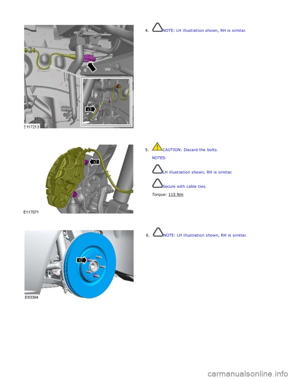
4. NOTE: LH illustration shown, RH is similar.
5. CAUTION: Discard the bolts.
NOTES:
LH illustration shown, RH is similar.
Secure with cable ties.
Torque: 115 Nm
6. NOTE: LH illustration shown, RH is similar.
Page 375 of 3039
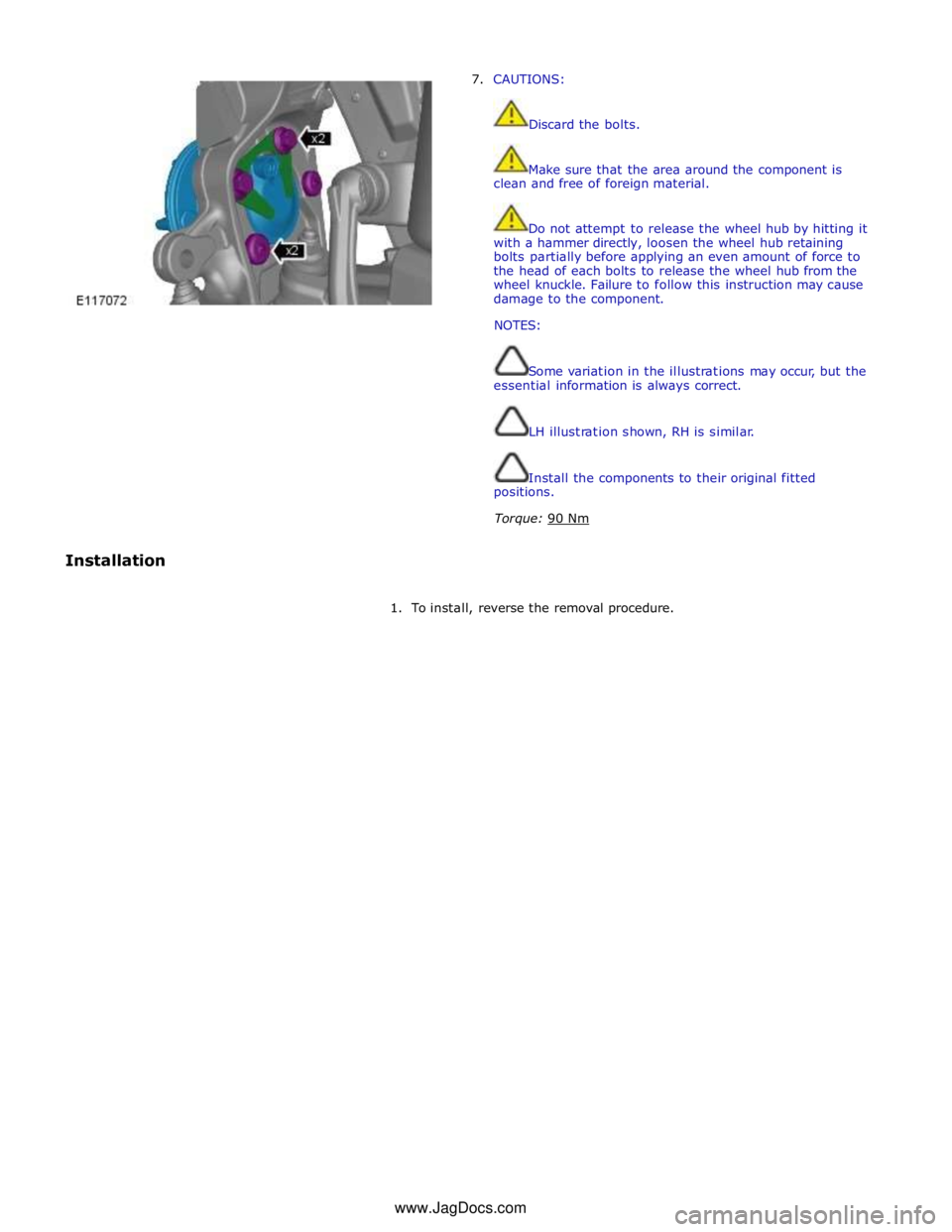
7. CAUTIONS:
Discard the bolts.
Make sure that the area around the component is
clean and free of foreign material.
Do not attempt to release the wheel hub by hitting it
with a hammer directly, loosen the wheel hub retaining
bolts partially before applying an even amount of force to
the head of each bolts to release the wheel hub from the
wheel knuckle. Failure to follow this instruction may cause
damage to the component.
NOTES:
Some variation in the illustrations may occur, but the
essential information is always correct.
LH illustration shown, RH is similar.
Install the components to their original fitted
positions.
Torque: 90 Nm
Installation
1. To install, reverse the removal procedure. www.JagDocs.com
Page 376 of 3039
Front Suspension - Wheel Knuckle
Removal and Installation Published: 11-May-2011
Removal
1. WARNING: Do not work on or under a vehicle supported only by a
jack. Always support the vehicle on safety stands.
Raise and support the vehicle.
2. Remove the hub assembly.
For additional information, refer to: Front Wheel Bearing and Wheel Hub - V6 3.0L Petrol (204-01 Front Suspension, Removal and Installation).
3. NOTE: LH illustration shown, RH is similar.
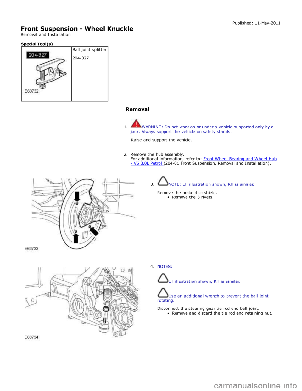
Remove the brake disc shield.
Remove the 3 rivets.
4. NOTES:
LH illustration shown, RH is similar.
Use an additional wrench to prevent the ball joint
rotating.
Disconnect the steering gear tie rod end ball joint.
Remove and discard the tie rod end retaining nut. Ball joint splitter
204-327 Special Tool(s)
Page 377 of 3039
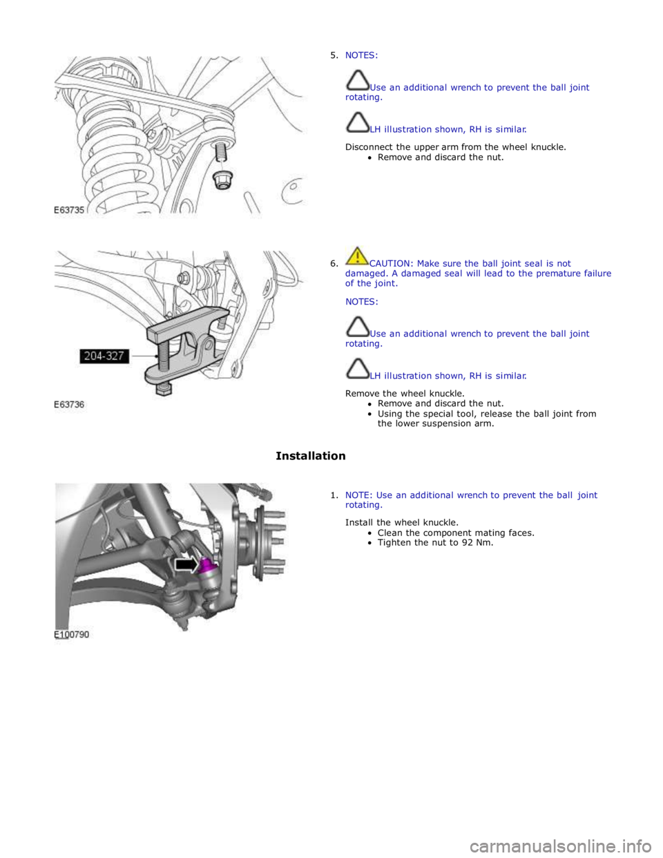
5. NOTES:
Use an additional wrench to prevent the ball joint
rotating.
LH illustration shown, RH is similar.
Disconnect the upper arm from the wheel knuckle.
Remove and discard the nut.
6. CAUTION: Make sure the ball joint seal is not
damaged. A damaged seal will lead to the premature failure
of the joint.
NOTES:
Use an additional wrench to prevent the ball joint
rotating.
LH illustration shown, RH is similar.
Remove the wheel knuckle.
Remove and discard the nut.
Using the special tool, release the ball joint from
the lower suspension arm.
Installation
1. NOTE: Use an additional wrench to prevent the ball joint
rotating.
Install the wheel knuckle.
Clean the component mating faces.
Tighten the nut to 92 Nm.
Page 378 of 3039
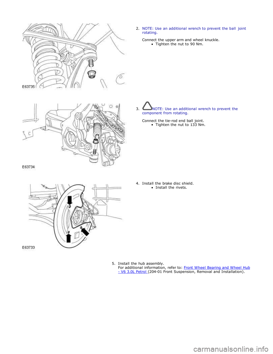
2. NOTE: Use an additional wrench to prevent the ball joint
rotating.
Connect the upper arm and wheel knuckle.
Tighten the nut to 90 Nm.
3. NOTE: Use an additional wrench to prevent the
component from rotating.
Connect the tie-rod end ball joint.
Tighten the nut to 133 Nm.
4. Install the brake disc shield.
Install the rivets.
5. Install the hub assembly.
For additional information, refer to: Front Wheel Bearing and Wheel Hub - V6 3.0L Petrol (204-01 Front Suspension, Removal and Installation).
Page 379 of 3039
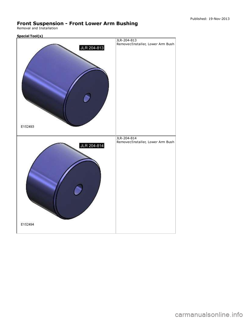
JLR-204-814
Remover/Installer, Lower Arm Bush
Page 380 of 3039
General Equipment
Removal
NOTE: Removal and installation of the bush requires the use of a press.
1. Visually inspect the lower arm for signs of a center punch mark. If
four marks are located on the lower arm in the area illustrated,
install a new front lower arm.
Center punch
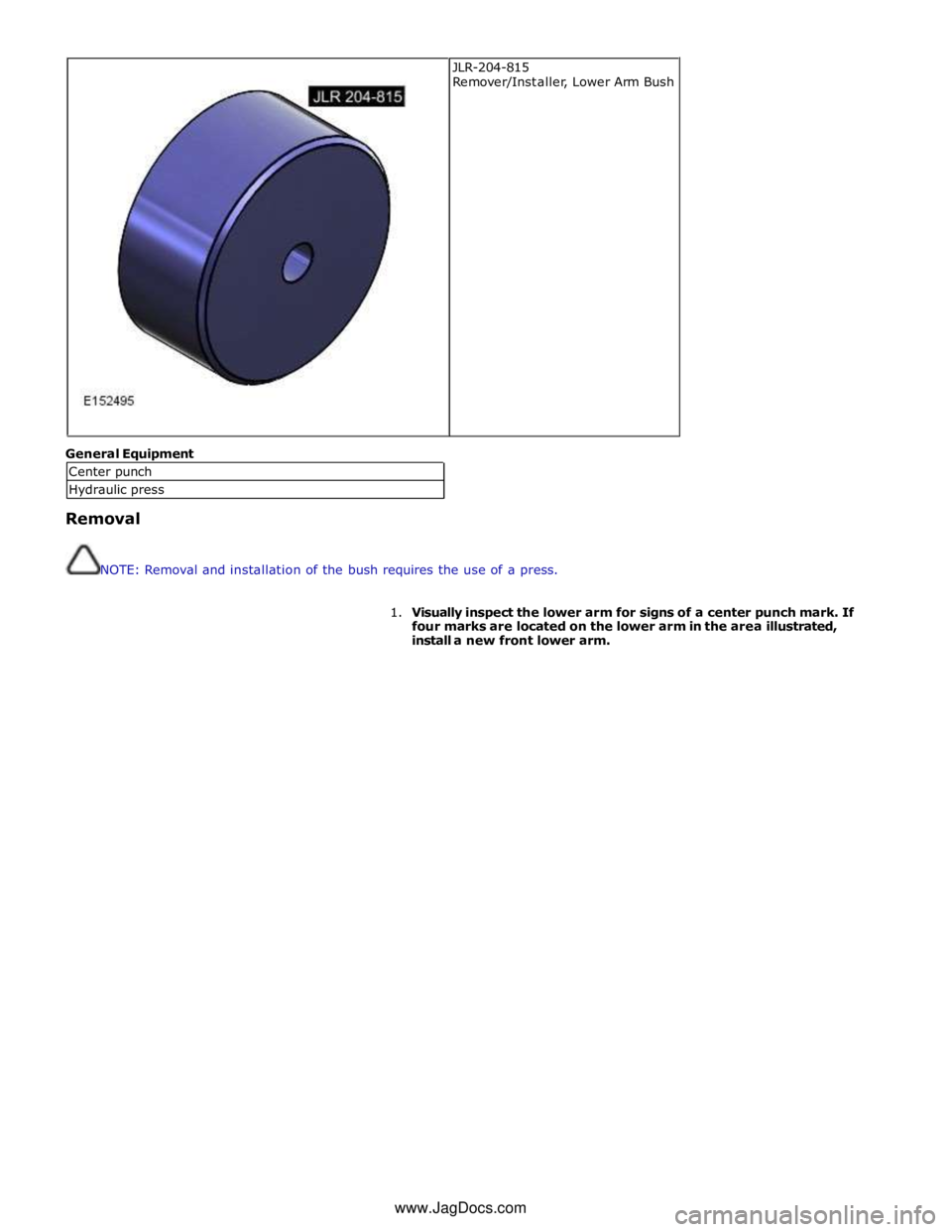
Hydraulic press JLR-204-815
Remover/Installer, Lower Arm Bush
www.JagDocs.com
Trending: P254F13, power steering fluid, trunk release, height adjustment, oil filler, C1a04-64, PID
