JAGUAR XFR 2010 1.G Workshop Manual
XFR 2010 1.G
JAGUAR
JAGUAR
https://www.carmanualsonline.info/img/21/7642/w960_7642-0.png
JAGUAR XFR 2010 1.G Workshop Manual
Trending: open gas tank, fuse, keyless entry, hood open, dead battery, manual radio set, service
Page 361 of 3039
22.
23. Torque:
M6 9 Nm M10 40 Nm
CAUTIONS:
Support the engine on a jack. The angle may need to
be adjusted during this procedure.
Make sure to protect the paintwork.
Special Tool(s): 303-021
24. WARNING: Do not work on or under a vehicle supported only by a
jack. Always support the vehicle on safety stands.
Raise and support the vehicle.
25. www.JagDocs.com
Page 362 of 3039
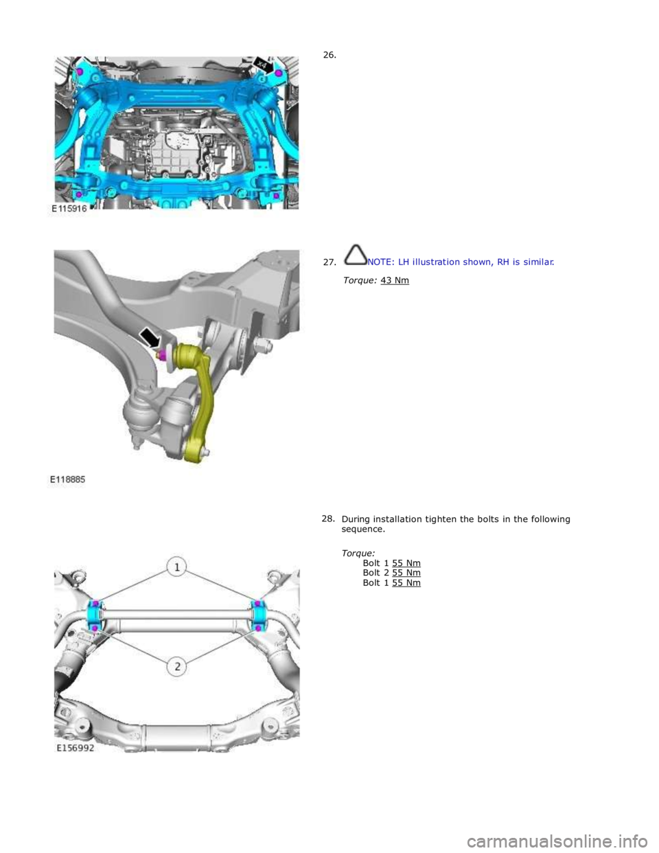
26.
27.
28.
NOTE: LH illustration shown, RH is similar.
Torque: 43 Nm
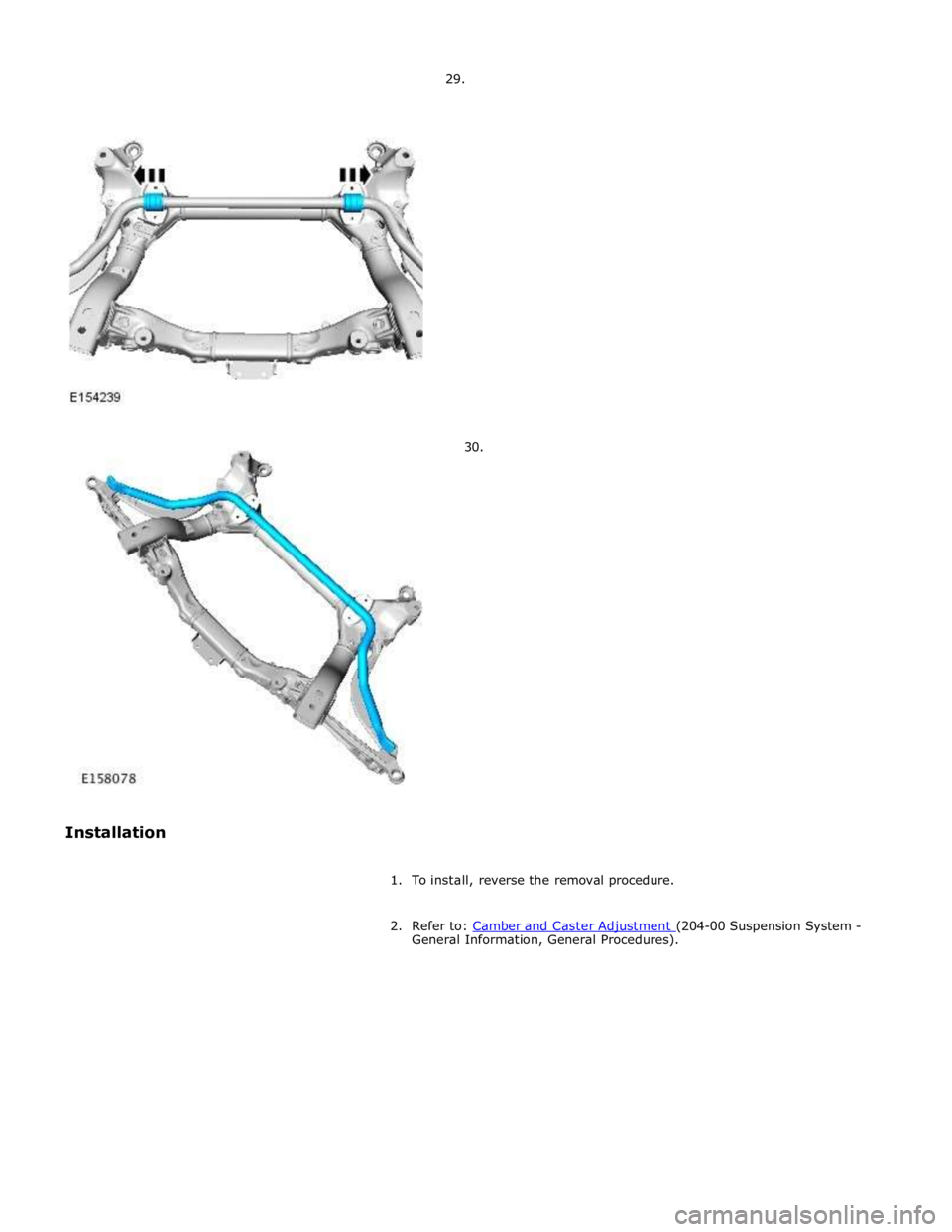
During installation tighten the bolts in the following
sequence.
Torque:
Bolt 1 55 Nm Bolt 2 55 Nm Bolt 1 55 Nm
Page 363 of 3039
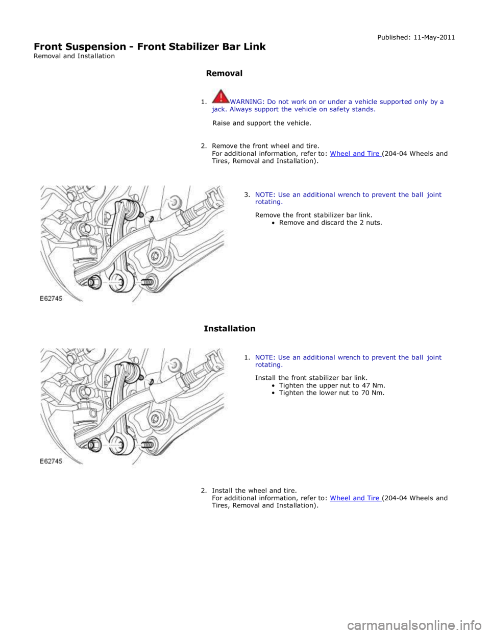
General Information, General Procedures).
Page 364 of 3039
Tires, Removal and Installation).
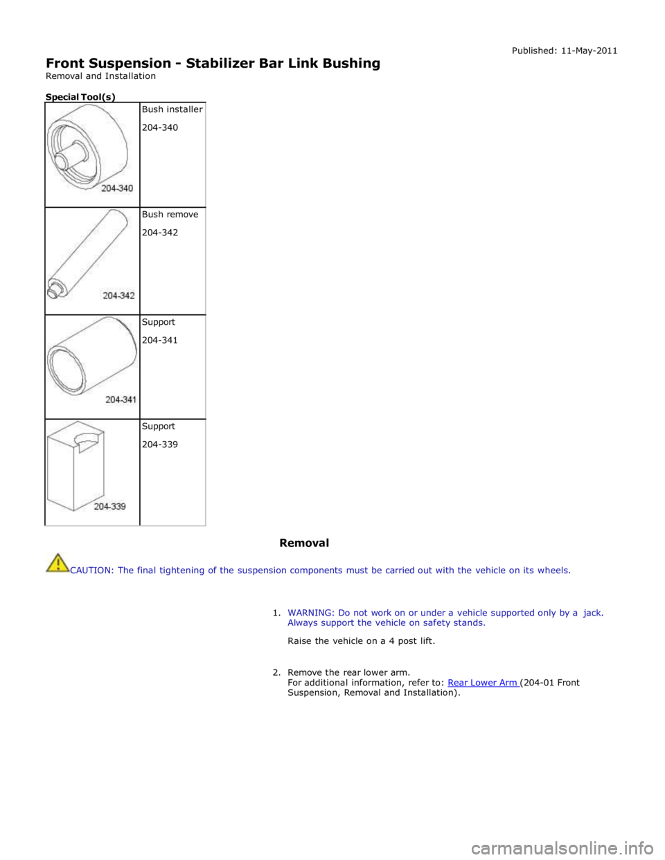
3. NOTE: Use an additional wrench to prevent the ball joint
rotating.
Remove the front stabilizer bar link.
Remove and discard the 2 nuts.
Installation
1. NOTE: Use an additional wrench to prevent the ball joint
rotating.
Install the front stabilizer bar link.
Tighten the upper nut to 47 Nm.
Tighten the lower nut to 70 Nm.
2. Install the wheel and tire.
For additional information, refer to: Wheel and Tire (204-04 Wheels and Tires, Removal and Installation).
Page 365 of 3039
Front Suspension - Stabilizer Bar Link Bushing
Removal and Installation
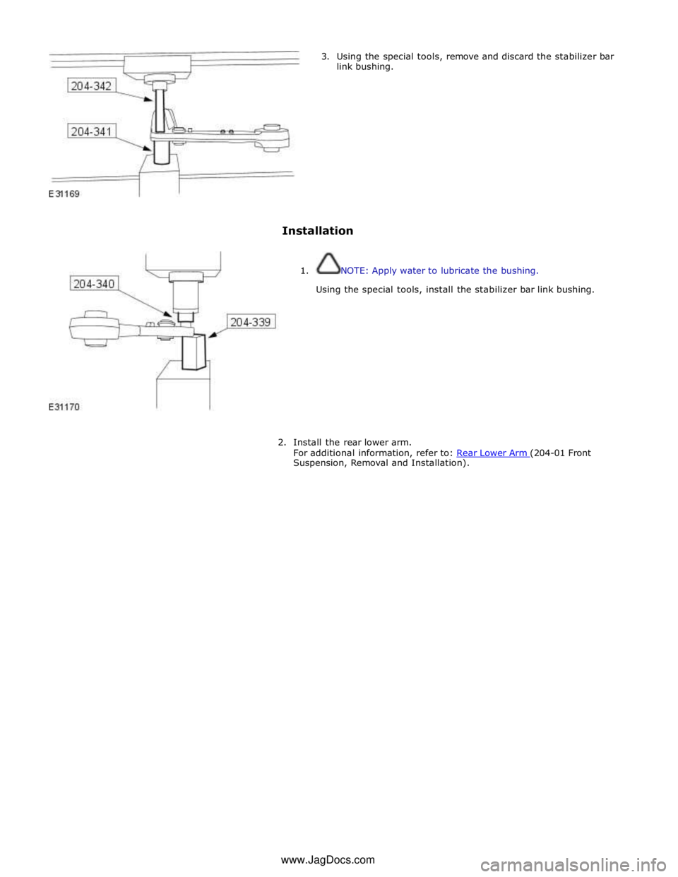
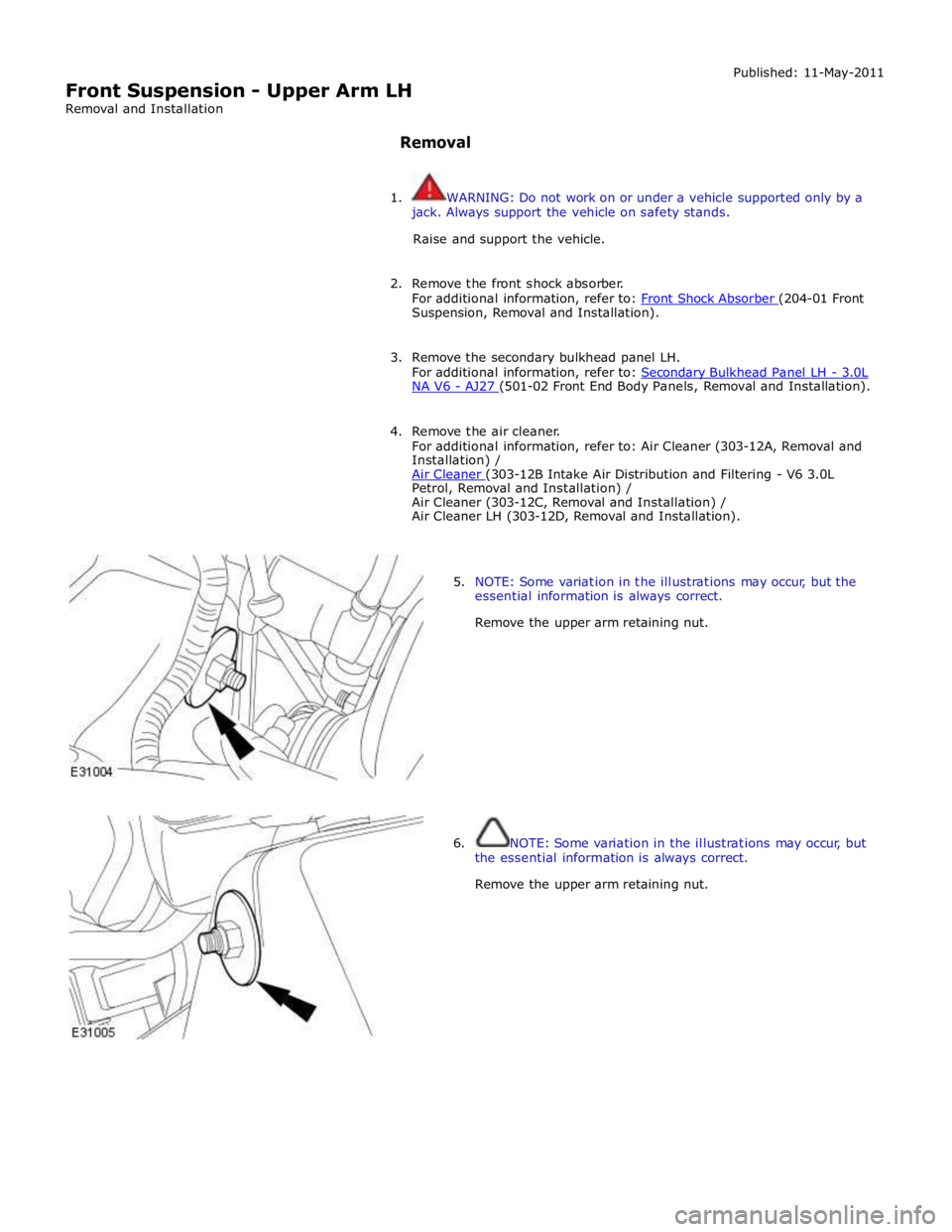
Special Tool(s)
Bush installer
204-340
Bush remove
204-342
Support
204-341
Support
204-339 Removal Published: 11-May-2011
CAUTION: The final tightening of the suspension components must be carried out with the vehicle on its wheels.
1. WARNING: Do not work on or under a vehicle supported only by a jack.
Always support the vehicle on safety stands.
Raise the vehicle on a 4 post lift.
2. Remove the rear lower arm.
For additional information, refer to: Rear Lower Arm (204-01 Front Suspension, Removal and Installation).
Page 366 of 3039
3. Using the special tools, remove and discard the stabilizer bar
link bushing.
Installation
1. NOTE: Apply water to lubricate the bushing.
Using the special tools, install the stabilizer bar link bushing.
2. Install the rear lower arm.
For additional information, refer to: Rear Lower Arm (204-01 Front Suspension, Removal and Installation). www.JagDocs.com
Page 367 of 3039
Suspension, Removal and Installation).
3. Remove the secondary bulkhead panel LH.
For additional information, refer to: Secondary Bulkhead Panel LH - 3.0L NA V6 - AJ27 (501-02 Front End Body Panels, Removal and Installation).
4. Remove the air cleaner.
For additional information, refer to: Air Cleaner (303-12A, Removal and
Installation) /
Air Cleaner (303-12B Intake Air Distribution and Filtering - V6 3.0L Petrol, Removal and Installation) /
Air Cleaner (303-12C, Removal and Installation) /
Air Cleaner LH (303-12D, Removal and Installation).
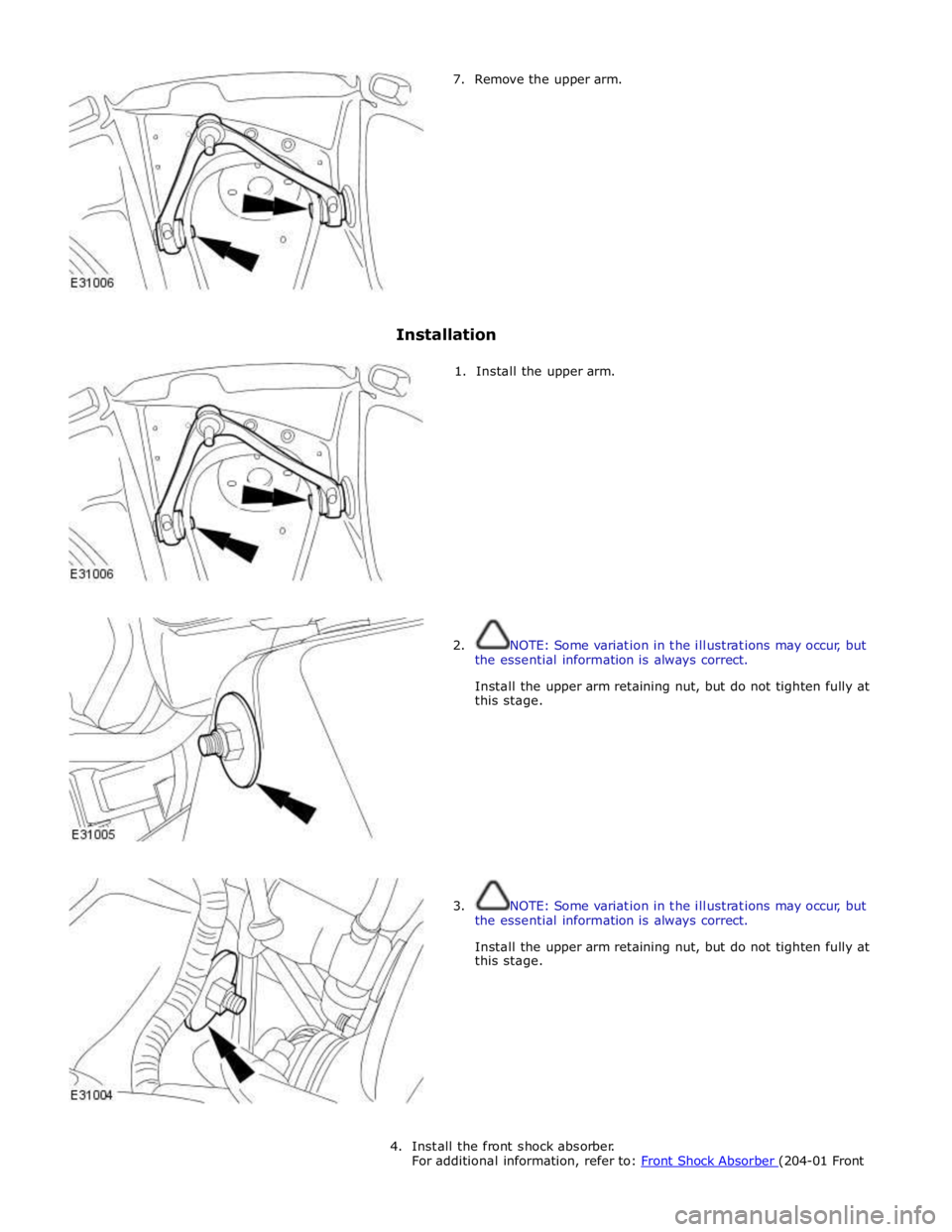
5. NOTE: Some variation in the illustrations may occur, but the
essential information is always correct.
Remove the upper arm retaining nut.
6. NOTE: Some variation in the illustrations may occur, but
the essential information is always correct.
Remove the upper arm retaining nut.
Page 368 of 3039
Page 369 of 3039
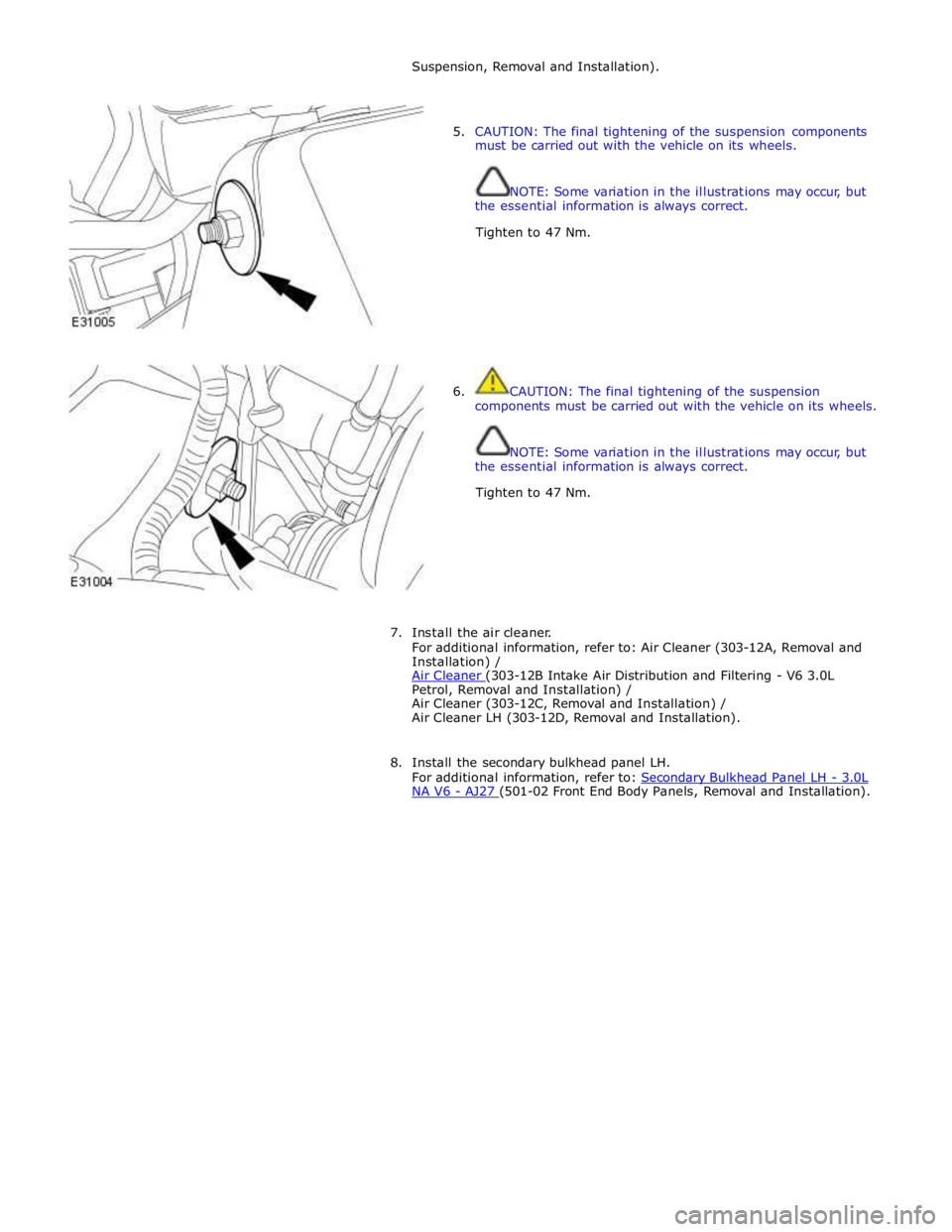
Suspension, Removal and Installation).
5. CAUTION: The final tightening of the suspension components
must be carried out with the vehicle on its wheels.
NOTE: Some variation in the illustrations may occur, but
the essential information is always correct.
Tighten to 47 Nm.
6. CAUTION: The final tightening of the suspension
components must be carried out with the vehicle on its wheels.
NOTE: Some variation in the illustrations may occur, but
the essential information is always correct.
Tighten to 47 Nm.
7. Install the air cleaner.
For additional information, refer to: Air Cleaner (303-12A, Removal and
Installation) /
Air Cleaner (303-12B Intake Air Distribution and Filtering - V6 3.0L Petrol, Removal and Installation) /
Air Cleaner (303-12C, Removal and Installation) /
Air Cleaner LH (303-12D, Removal and Installation).
8. Install the secondary bulkhead panel LH.
For additional information, refer to: Secondary Bulkhead Panel LH - 3.0L NA V6 - AJ27 (501-02 Front End Body Panels, Removal and Installation).
Page 370 of 3039
Suspension, Removal and Installation).
3. Remove the secondary bulkhead panel RH.
For additional information, refer to: Secondary Bulkhead Panel RH - 3.0L NA V6 - AJ27 (501-02 Front End Body Panels, Removal and Installation).
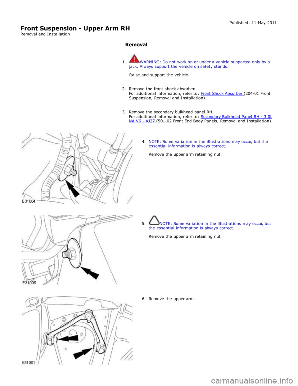
4. NOTE: Some variation in the illustrations may occur, but the
essential information is always correct.
Remove the upper arm retaining nut.
5. NOTE: Some variation in the illustrations may occur, but
the essential information is always correct.
Remove the upper arm retaining nut.
6. Remove the upper arm.
Trending: fog light bulb, wiper, B100a-64, tow, electrical wiring diagrams, remote start, low oil pressure

