Transmission mount JAGUAR XFR 2010 1.G Owner's Guide
[x] Cancel search | Manufacturer: JAGUAR, Model Year: 2010, Model line: XFR, Model: JAGUAR XFR 2010 1.GPages: 3039, PDF Size: 58.49 MB
Page 1535 of 3039
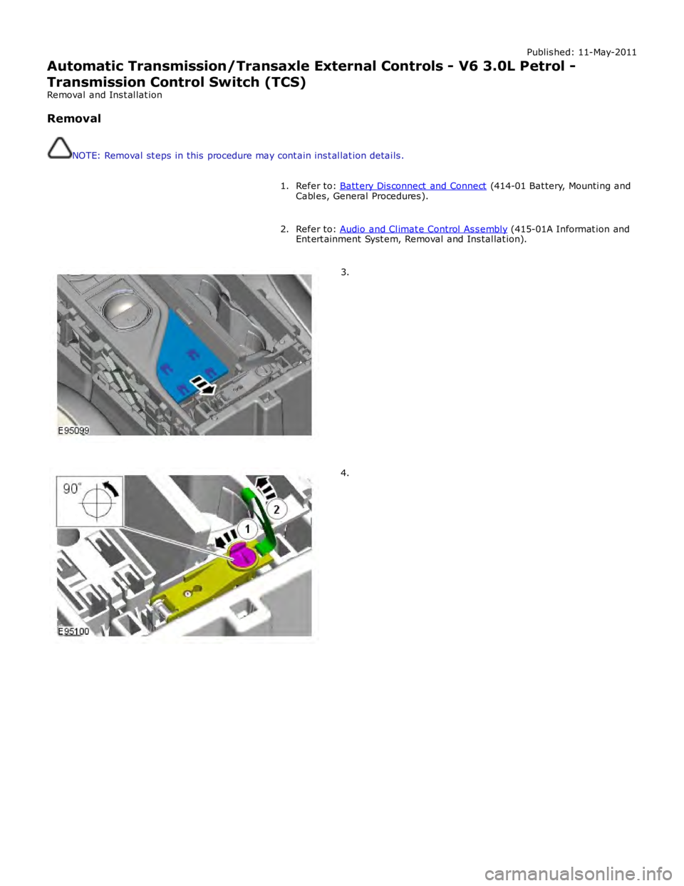
Published: 11-May-2011
Automatic Transmission/Transaxle External Controls - V6 3.0L Petrol -
Transmission Control Switch (TCS)
Removal and Installation
Removal
NOTE: Removal steps in this procedure may contain inst allation details.
Refer to: Batt ery Disconnect and Connect (414-01 Battery, Mounting and
Cables, General Procedures). 1.
Refer to: Audio and Climate Control Assembly (415-01A Informat ion and
Entert ainment Syst em, Removal and Installat ion). 2.3.4.
Page 1539 of 3039

Published: 11-May-2011
Automatic Transmission/Transaxle External Controls - V6 3.0L Petrol -
Emergency Park Position Release Lever
Removal and Installation
Removal
NOTE: Removal steps in this procedure may contain inst allation details.
Refer to: Batt ery Disconnect and Connect (414-01 Battery, Mounting and
Cables, General Procedures). 1.
Refer to: Air Deflector (501-02, Removal and Installation). 2.
Refer to: Engine Rear Undershield (501-02 Front End Body Panels,
Removal and Installation). 3.
Refer to: Floor Console Side Trim Panel (501-12 Inst rument Panel and
Console, Removal and Installation). 4.WARNING: Make sure to support the vehicle with axle
stands.
T orque: 11 Nm 5.
Page 1641 of 3039
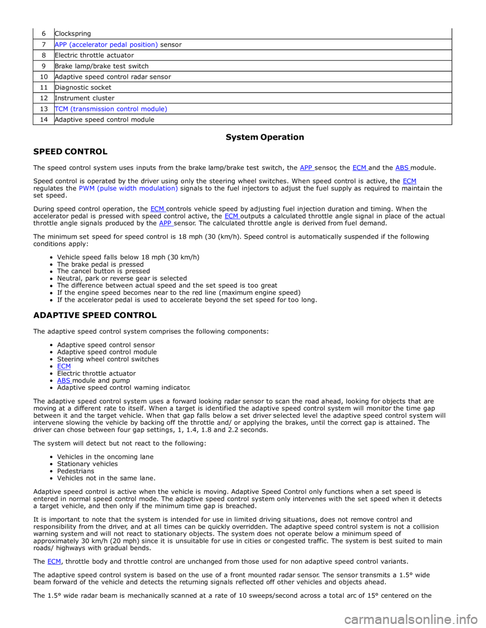
6 Clockspring 7 APP (accelerator pedal position) sensor 8 Electric throttle actuator 9 Brake lamp/brake test switch 10 Adaptive speed control radar sensor 11 Diagnostic socket 12 Instrument cluster 13 TCM (transmission control module) 14 Adaptive speed control module
SPEED CONTROL System Operation
The speed control system uses inputs from the brake lamp/brake test switch, the APP sensor, the ECM and the ABS module.
Speed control is operated by the driver using only the steering wheel switches. When speed control is active, the ECM regulates the PWM (pulse width modulation) signals to the fuel injectors to adjust the fuel supply as required to maintain the
set speed.
During speed control operation, the ECM controls vehicle speed by adjusting fuel injection duration and timing. When the accelerator pedal is pressed with speed control active, the ECM outputs a calculated throttle angle signal in place of the actual throttle angle signals produced by the APP sensor. The calculated throttle angle is derived from fuel demand.
The minimum set speed for speed control is 18 mph (30 (km/h). Speed control is automatically suspended if the following
conditions apply:
Vehicle speed falls below 18 mph (30 km/h)
The brake pedal is pressed
The cancel button is pressed
Neutral, park or reverse gear is selected
The difference between actual speed and the set speed is too great
If the engine speed becomes near to the red line (maximum engine speed)
If the accelerator pedal is used to accelerate beyond the set speed for too long.
ADAPTIVE SPEED CONTROL
The adaptive speed control system comprises the following components:
Adaptive speed control sensor
Adaptive speed control module
Steering wheel control switches
ECM
Electric throttle actuator
ABS module and pump Adaptive speed control warning indicator.
The adaptive speed control system uses a forward looking radar sensor to scan the road ahead, looking for objects that are
moving at a different rate to itself. When a target is identified the adaptive speed control system will monitor the time gap
between it and the target vehicle. When that gap falls below a set driver selected level the adaptive speed control system will
intervene slowing the vehicle by backing off the throttle and/ or applying the brakes, until the correct gap is attained. The
driver can chose between four gap settings, 1, 1.4, 1.8 and 2.2 seconds.
The system will detect but not react to the following:
Vehicles in the oncoming lane
Stationary vehicles
Pedestrians
Vehicles not in the same lane.
Adaptive speed control is active when the vehicle is moving. Adaptive Speed Control only functions when a set speed is
entered in normal speed control mode. The adaptive speed control system only intervenes with the set speed when it detects
a target vehicle, and then only if the minimum time gap is breached.
It is important to note that the system is intended for use in limited driving situations, does not remove control and
responsibility from the driver, and at all times can be quickly overridden. The adaptive speed control system is not a collision
warning system and will not react to stationary objects. The system does not operate below a minimum speed of
approximately 30 km/h (20 mph) since it is unsuitable for use in cities or congested traffic. The system is best suited to main
roads/ highways with gradual bends.
The ECM, throttle body and throttle control are unchanged from those used for non adaptive speed control variants.
The adaptive speed control system is based on the use of a front mounted radar sensor. The sensor transmits a 1.5° wide
beam forward of the vehicle and detects the returning signals reflected off other vehicles and objects ahead.
The 1.5° wide radar beam is mechanically scanned at a rate of 10 sweeps/second across a total arc of 15° centered on the
Page 1822 of 3039
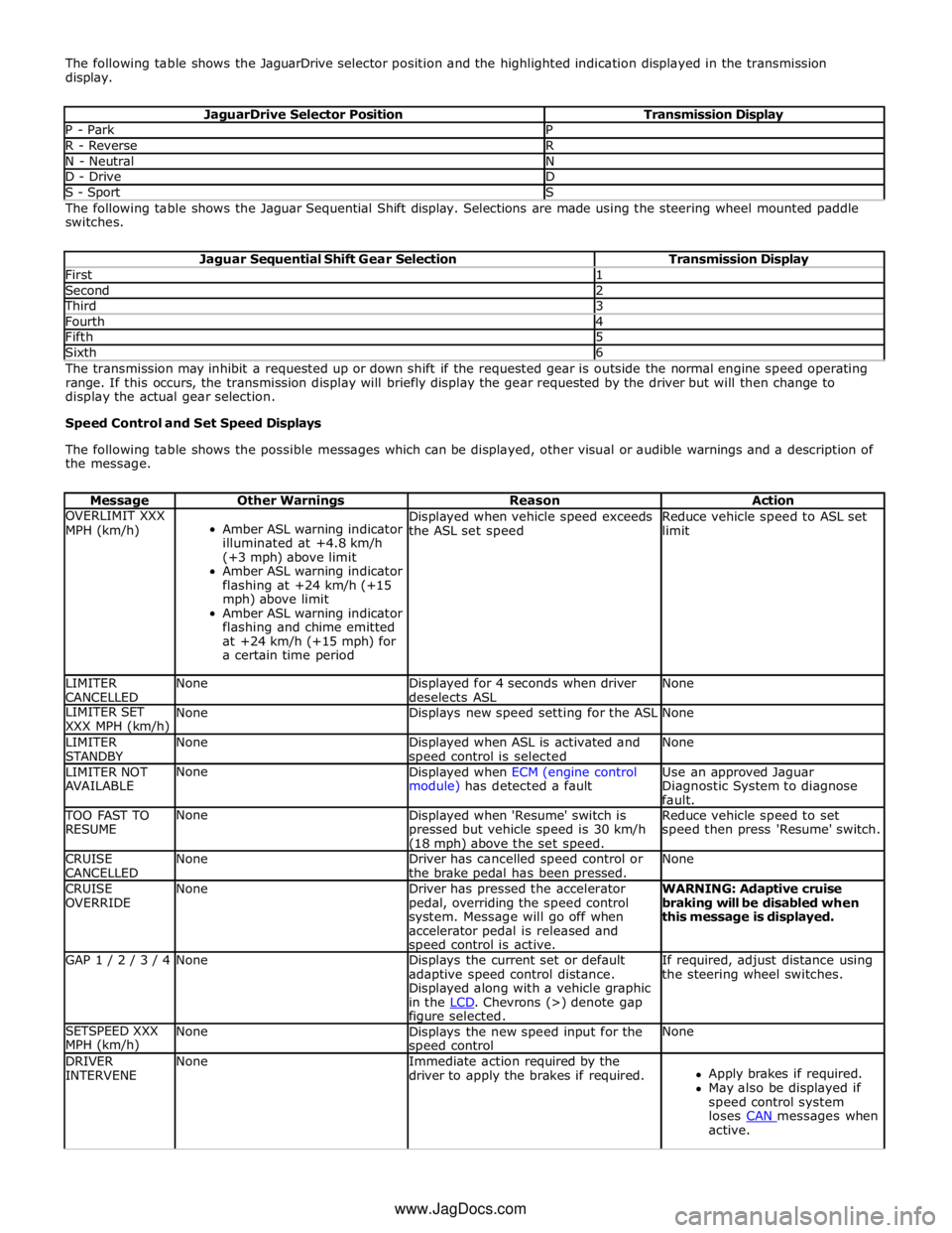
The following table shows the JaguarDrive selector position and the highlighted indication displayed in the transmission
display.
JaguarDrive Selector Position Transmission Display P - Park P R - Reverse R N - Neutral N D - Drive D S - Sport S The following table shows the Jaguar Sequential Shift display. Selections are made using the steering wheel mounted paddle
switches.
Jaguar Sequential Shift Gear Selection Transmission Display First 1 Second 2 Third 3 Fourth 4 Fifth 5 Sixth 6 The transmission may inhibit a requested up or down shift if the requested gear is outside the normal engine speed operating
range. If this occurs, the transmission display will briefly display the gear requested by the driver but will then change to
display the actual gear selection.
Speed Control and Set Speed Displays
The following table shows the possible messages which can be displayed, other visual or audible warnings and a description of
the message.
Message Other Warnings Reason Action OVERLIMIT XXX
MPH (km/h)
Amber ASL warning indicator
illuminated at +4.8 km/h
(+3 mph) above limit
Amber ASL warning indicator
flashing at +24 km/h (+15
mph) above limit
Amber ASL warning indicator
flashing and chime emitted
at +24 km/h (+15 mph) for
a certain time period Displayed when vehicle speed exceeds
the ASL set speed Reduce vehicle speed to ASL set
limit LIMITER
CANCELLED None
Displayed for 4 seconds when driver
deselects ASL None LIMITER SET
XXX MPH (km/h) None Displays new speed setting for the ASL None LIMITER
STANDBY None
Displayed when ASL is activated and speed control is selected None LIMITER NOT
AVAILABLE None
Displayed when ECM (engine control
module) has detected a fault Use an approved Jaguar
Diagnostic System to diagnose
fault. TOO FAST TO
RESUME None
Displayed when 'Resume' switch is
pressed but vehicle speed is 30 km/h (18 mph) above the set speed. Reduce vehicle speed to set
speed then press 'Resume' switch. CRUISE
CANCELLED None
Driver has cancelled speed control or
the brake pedal has been pressed. None CRUISE
OVERRIDE None
Driver has pressed the accelerator
pedal, overriding the speed control
system. Message will go off when
accelerator pedal is released and speed control is active. WARNING: Adaptive cruise
braking will be disabled when
this message is displayed. GAP 1 / 2 / 3 / 4 None
Displays the current set or default
adaptive speed control distance.
Displayed along with a vehicle graphic
in the LCD. Chevrons (>) denote gap figure selected. If required, adjust distance using
the steering wheel switches. SETSPEED XXX
MPH (km/h) None
Displays the new speed input for the speed control None DRIVER
INTERVENE None
Immediate action required by the
driver to apply the brakes if required.
Apply brakes if required.
May also be displayed if
speed control system
loses CAN messages when active. www.JagDocs.com
Page 2294 of 3039
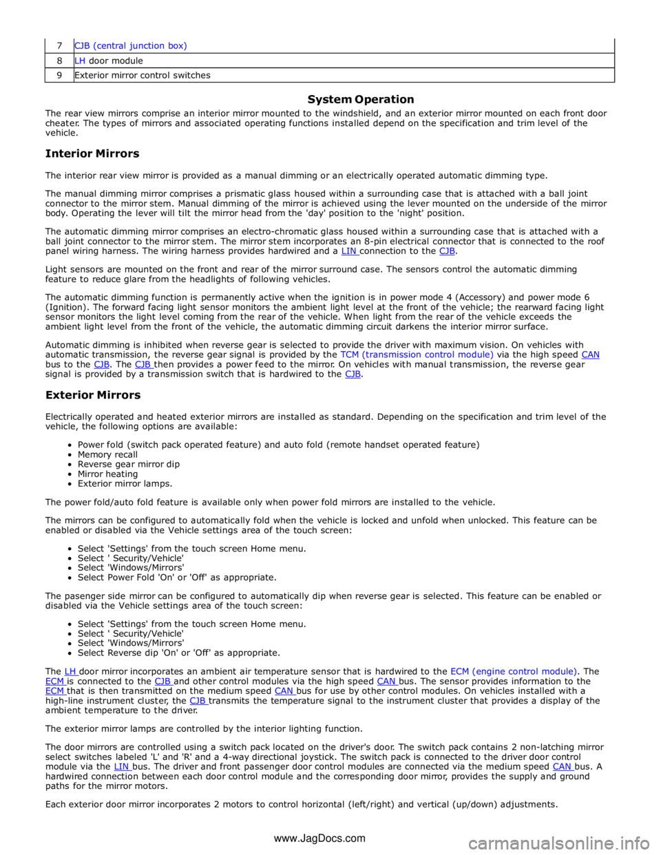
8 LH door module 9 Exterior mirror control switches
System Operation
The rear view mirrors comprise an interior mirror mounted to the windshield, and an exterior mirror mounted on each front door
cheater. The types of mirrors and associated operating functions installed depend on the specification and trim level of the
vehicle.
Interior Mirrors
The interior rear view mirror is provided as a manual dimming or an electrically operated automatic dimming type.
The manual dimming mirror comprises a prismatic glass housed within a surrounding case that is attached with a ball joint
connector to the mirror stem. Manual dimming of the mirror is achieved using the lever mounted on the underside of the mirror
body. Operating the lever will tilt the mirror head from the 'day' position to the 'night' position.
The automatic dimming mirror comprises an electro-chromatic glass housed within a surrounding case that is attached with a
ball joint connector to the mirror stem. The mirror stem incorporates an 8-pin electrical connector that is connected to the roof
panel wiring harness. The wiring harness provides hardwired and a LIN connection to the CJB.
Light sensors are mounted on the front and rear of the mirror surround case. The sensors control the automatic dimming
feature to reduce glare from the headlights of following vehicles.
The automatic dimming function is permanently active when the ignition is in power mode 4 (Accessory) and power mode 6
(Ignition). The forward facing light sensor monitors the ambient light level at the front of the vehicle; the rearward facing light
sensor monitors the light level coming from the rear of the vehicle. When light from the rear of the vehicle exceeds the
ambient light level from the front of the vehicle, the automatic dimming circuit darkens the interior mirror surface.
Automatic dimming is inhibited when reverse gear is selected to provide the driver with maximum vision. On vehicles with
automatic transmission, the reverse gear signal is provided by the TCM (transmission control module) via the high speed CAN bus to the CJB. The CJB then provides a power feed to the mirror. On vehicles with manual transmission, the reverse gear signal is provided by a transmission switch that is hardwired to the CJB.
Exterior Mirrors
Electrically operated and heated exterior mirrors are installed as standard. Depending on the specification and trim level of the
vehicle, the following options are available:
Power fold (switch pack operated feature) and auto fold (remote handset operated feature)
Memory recall
Reverse gear mirror dip
Mirror heating
Exterior mirror lamps.
The power fold/auto fold feature is available only when power fold mirrors are installed to the vehicle.
The mirrors can be configured to automatically fold when the vehicle is locked and unfold when unlocked. This feature can be
enabled or disabled via the Vehicle settings area of the touch screen:
Select 'Settings' from the touch screen Home menu.
Select ' Security/Vehicle'
Select 'Windows/Mirrors'
Select Power Fold 'On' or 'Off' as appropriate.
The pasenger side mirror can be configured to automatically dip when reverse gear is selected. This feature can be enabled or
disabled via the Vehicle settings area of the touch screen:
Select 'Settings' from the touch screen Home menu.
Select ' Security/Vehicle'
Select 'Windows/Mirrors'
Select Reverse dip 'On' or 'Off' as appropriate.
The LH door mirror incorporates an ambient air temperature sensor that is hardwired to the ECM (engine control module). The ECM is connected to the CJB and other control modules via the high speed CAN bus. The sensor provides information to the ECM that is then transmitted on the medium speed CAN bus for use by other control modules. On vehicles installed with a high-line instrument cluster, the CJB transmits the temperature signal to the instrument cluster that provides a display of the ambient temperature to the driver.
The exterior mirror lamps are controlled by the interior lighting function.
The door mirrors are controlled using a switch pack located on the driver's door. The switch pack contains 2 non-latching mirror
select switches labeled 'L' and 'R' and a 4-way directional joystick. The switch pack is connected to the driver door control
module via the LIN bus. The driver and front passenger door control modules are connected via the medium speed CAN bus. A hardwired connection between each door control module and the corresponding door mirror, provides the supply and ground
paths for the mirror motors.
Each exterior door mirror incorporates 2 motors to control horizontal (left/right) and vertical (up/down) adjustments. www.JagDocs.com
Page 2459 of 3039
Published: 11-May-2011
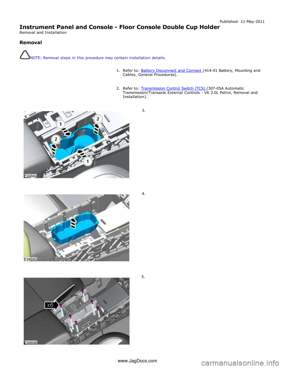
Instrument Panel and Console - Floor Console Double Cup Holder
Removal and Installation
Removal
NOTE: Removal steps in this procedure may contain installation details.
1. Refer to: Battery Disconnect and Connect (414-01 Battery, Mounting and Cables, General Procedures).
2. Refer to: Transmission Control Switch (TCS) (307-05A Automatic Transmission/Transaxle External Controls - V6 3.0L Petrol, Removal and
Installation).
3.
4.
5. www.JagDocs.com
Page 2707 of 3039
For instance, the crumple zones absorb the bulk of the impact energy. If any unprofessional repair techniques or
methods are used in these areas then this can pose a fundamental threat to vehicle safety.
Hidden damage
As well as looking at external indicators like flaked off paint, it is vital to check for hidden body damage or deformation
that is not visible from the outside. Large attached parts like bumpers and inner fenders often need to be removed to
allow accurate assessment of damage to underlying body parts.
Gap dimensions
Gap dimensions offer another alternative for diagnosis by visual inspection. If any changes or misaligned edges are apparent,
then this usually indicates that the dimensions of the affected part are incorrect.
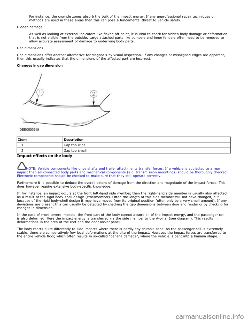
Changes in gap dimension
Item
Description 1
Gap too wide 2
Gap too small Impact effects on the body
NOTE: Vehicle components like drive shafts and trailer attachments transfer forces. If a vehicle is subjected to a rear
impact then all connected body parts and mechanical components (e.g. transmission mountings) should be thoroughly checked.
Electronic components should be checked to make sure that they still operate correctly.
Furthermore it is possible to deduce the overall extent of damage from the direction and magnitude of the impact forces. This
does however require extensive body-specific knowledge.
If, for instance, an impact occurs at the front left-hand side member, then the right-hand side member is usually also affected
as a result of the rigid body-shell design (crossmember). Often the length of this side member will not have changed, but
because of the rigid body-shell design it may have moved from its original position (often only by a very small amount). If any
deviations are present this can usually be detected by checking the gap dimensions between door and fender or by checking for
changes in dimension.
In the case of more severe impacts, the front part of the body cannot absorb all of the impact energy, and the passenger cell
is also deformed. Here the impact energy is transferred via the side member to the A-pillar (see diagram). This results in
deformations in the area of the roof and the door rocker panel.
The body reacts quite differently to side impacts where there is hardly any crumple zone. As the passenger cell is extremely
stable, there are comparatively few local deformations at the site of the impact. However, the impact forces are transferred to
the entire vehicle floor, which often results in so-called "banana damage", where the vehicle is bent into a banana shape.
Page 2738 of 3039
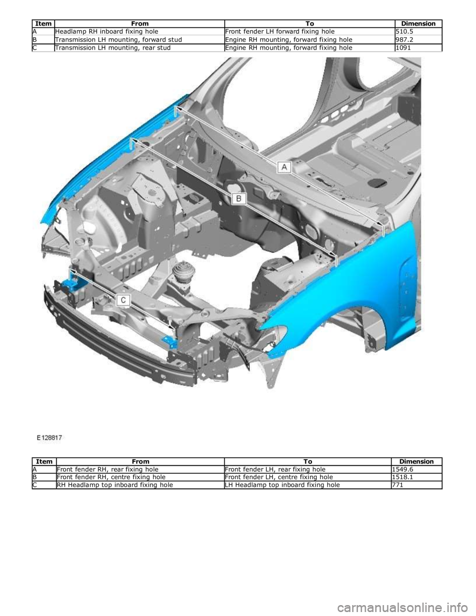
Item From To Dimension A Headlamp RH inboard fixing hole Front fender LH forward fixing hole 510.5 B Transmission LH mounting, forward stud Engine RH mounting, forward fixing hole 987.2 C Transmission LH mounting, rear stud Engine RH mounting, forward fixing hole 1091
Item From To Dimension A Front fender RH, rear fixing hole Front fender LH, rear fixing hole 1549.6 B Front fender RH, centre fixing hole Front fender LH, centre fixing hole 1518.1 C RH Headlamp top inboard fixing hole LH Headlamp top inboard fixing hole 771
Page 2784 of 3039
Front End Sheet Metal Repairs - Front Side Member
Removal and Installation
Removal Published: 11-May-2011
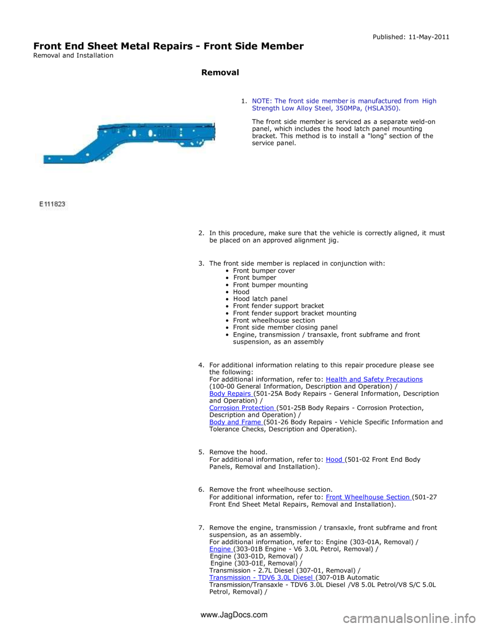
1. NOTE: The front side member is manufactured from High
Strength Low Alloy Steel, 350MPa, (HSLA350).
The front side member is serviced as a separate weld-on
panel, which includes the hood latch panel mounting
bracket. This method is to install a "long" section of the
service panel.
2. In this procedure, make sure that the vehicle is correctly aligned, it must
be placed on an approved alignment jig.
3. The front side member is replaced in conjunction with:
Front bumper cover
Front bumper
Front bumper mounting
Hood
Hood latch panel
Front fender support bracket
Front fender support bracket mounting
Front wheelhouse section
Front side member closing panel
Engine, transmission / transaxle, front subframe and front
suspension, as an assembly
4. For additional information relating to this repair procedure please see
the following:
For additional information, refer to: Health and Safety Precautions (100-00 General Information, Description and Operation) /
Body Repairs (501-25A Body Repairs - General Information, Description and Operation) /
Corrosion Protection (501-25B Body Repairs - Corrosion Protection, Description and Operation) /
Body and Frame (501-26 Body Repairs - Vehicle Specific Information and Tolerance Checks, Description and Operation).
5. Remove the hood.
For additional information, refer to: Hood (501-02 Front End Body Panels, Removal and Installation).
6. Remove the front wheelhouse section.
For additional information, refer to: Front Wheelhouse Section (501-27 Front End Sheet Metal Repairs, Removal and Installation).
7. Remove the engine, transmission / transaxle, front subframe and front
suspension, as an assembly.
For additional information, refer to: Engine (303-01A, Removal) /
Engine (303-01B Engine - V6 3.0L Petrol, Removal) / Engine (303-01D, Removal) /
Engine (303-01E, Removal) /
Transmission - 2.7L Diesel (307-01, Removal) /
Transmission - TDV6 3.0L Diesel (307-01B Automatic Transmission/Transaxle - TDV6 3.0L Diesel /V8 5.0L Petrol/V8 S/C 5.0L
Petrol, Removal) / www.JagDocs.com
Page 2785 of 3039
Transmission (307-01A Automatic Transmission/Transaxle - V6 3.0L Petrol, Removal) /
Transmission - 4.2L (307-01, Removal) /
Transmission - V8 5.0L Petrol/V8 S/C 5.0L Petrol (307-01B Automatic Transmission/Transaxle - TDV6 3.0L Diesel /V8 5.0L Petrol/V8 S/C 5.0L
Petrol, Removal) /
Front Shock Absorber (204-01 Front Suspension, Removal and Installation) /
Front Subframe - 2.7L Diesel (502-00, Removal and Installation) /
Front Subframe - V6 3.0L Petrol (502-00 Uni-Body, Subframe and Mounting System, Removal and Installation) /
Front Subframe - 4.2L, Vehicles Without: Supercharger (502-00, Removal
and Installation) /
Front Subframe - 4.2L, Vehicles With: Supercharger (502-00, Removal
and Installation).
8. Remove the pedestrian protection hood actuator.
For additional information, refer to: Pedestrian Protection Hood Actuator LH (501-20C Pedestrian Protection System, Removal and Installation) / Pedestrian Protection Hood Actuator RH (501-20C Pedestrian Protection System, Removal and Installation).
9. If the drivers side front side member and suspension top mount is to be
repaired, remove the brake master cylinder and reservoir.
For additional information, refer to: Brake Master Cylinder (206-06 Hydraulic Brake Actuation, Removal and Installation) /
Brake Fluid Reservoir (206-06 Hydraulic Brake Actuation, Removal and Installation).
10. If the left-hand front side member and suspension top mount assembly
is to be repaired, remove the fuel supply and return lines.
11. Release and position the front side member wiring harness to one side.
12. Remove any remaining miscellaneous components from the repair area.
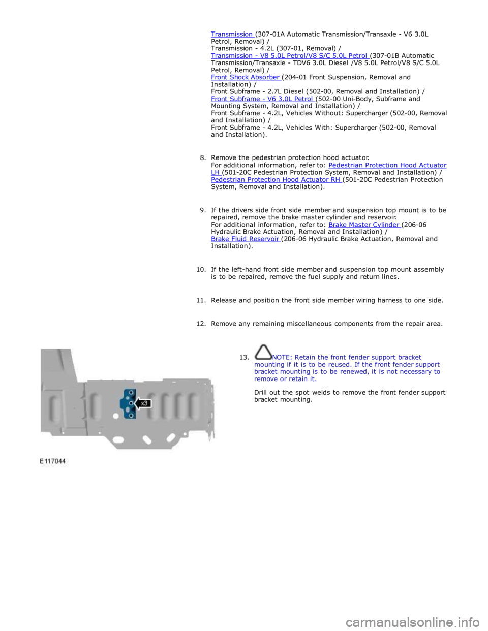
13. NOTE: Retain the front fender support bracket
mounting if it is to be reused. If the front fender support
bracket mounting is to be renewed, it is not necessary to
remove or retain it.
Drill out the spot welds to remove the front fender support
bracket mounting.