JAGUAR XFR 2010 1.G Workshop Manual
XFR 2010 1.G
JAGUAR
JAGUAR
https://www.carmanualsonline.info/img/21/7642/w960_7642-0.png
JAGUAR XFR 2010 1.G Workshop Manual
Trending: check oil, B100d-64, spark plug replacement, coolant capacity, snow chains, Drc, lug pattern
Page 421 of 3039
System - V6 3.0L Petrol, Removal and Installation).
19. Refill the fuel tank.
For additional information, refer to: Fuel Tank Draining (310-00 Fuel System - General Information, General Procedures).
20. Bleed the brake system.
For additional information, refer to: Brake System Bleeding (206-00 Brake System - General Information, General Procedures).
21. Install the rear wheels and tires.
For additional information, refer to: Wheel and Tire (204-04 Wheels and Tires, Removal and Installation).
22. Connect the battery ground cable.
For additional information, refer to: Battery Disconnect and Connect (414-01 Battery, Mounting and Cables, General Procedures).
23. Using only four-wheel alignment equipment approved by Jaguar, check
and adjust the wheel alignment.
For additional information, refer to: Camber and Caster Adjustment (204-00 Suspension System - General Information, General Procedures).
Page 422 of 3039
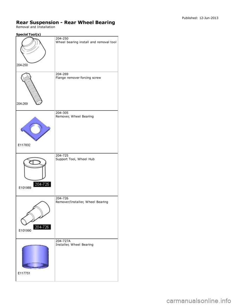
204-269
Flange remover forcing screw
204-305
Remover, Wheel Bearing
204-725
Support Tool, Wheel Hub
204-726
Remover/Installer, Wheel Bearing
204-727A
Installer, Wheel Bearing
Page 423 of 3039
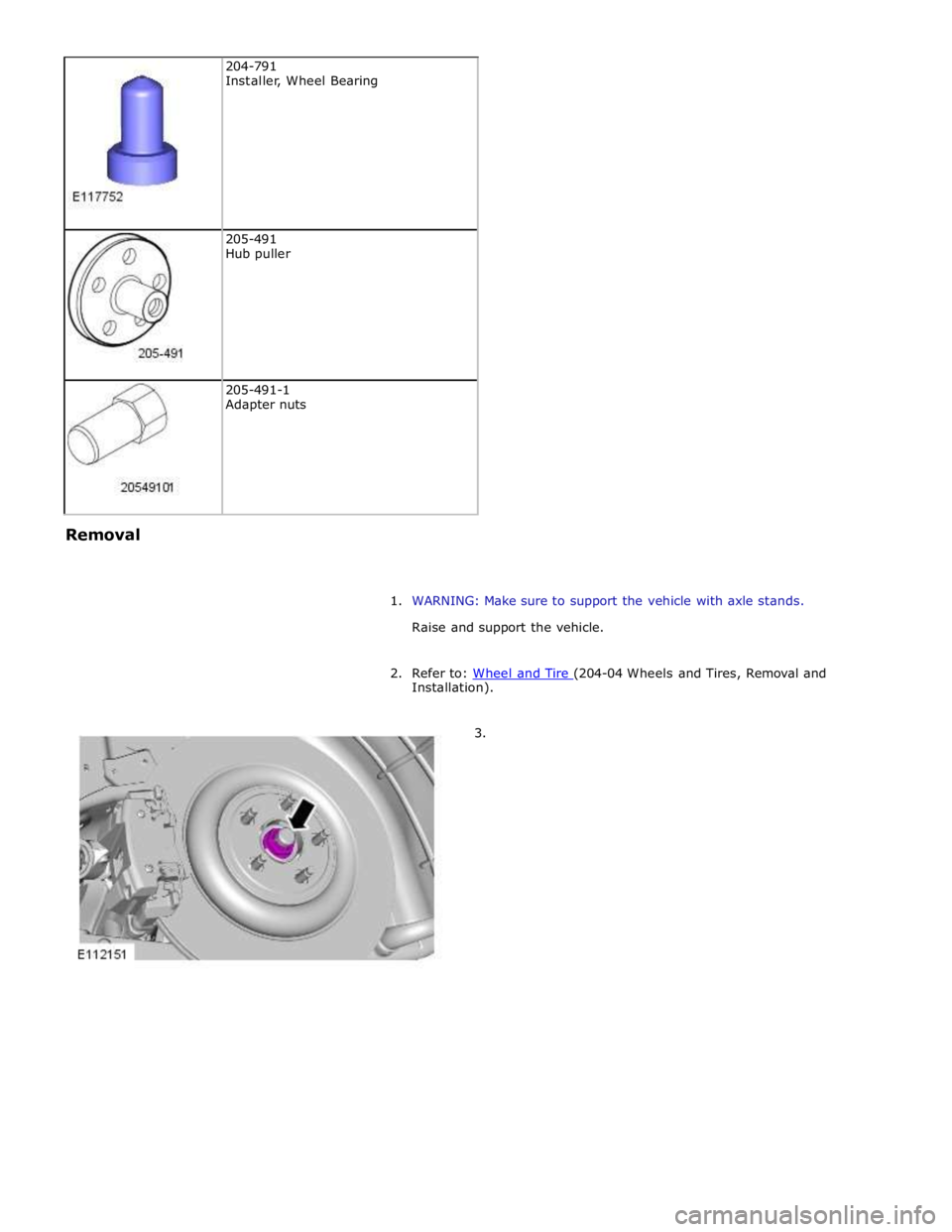
205-491
Hub puller
205-491-1
Adapter nuts Removal
1. WARNING: Make sure to support the vehicle with axle stands.
Raise and support the vehicle.
2. Refer to: Wheel and Tire (204-04 Wheels and Tires, Removal and Installation).
3.
Page 424 of 3039
Page 425 of 3039
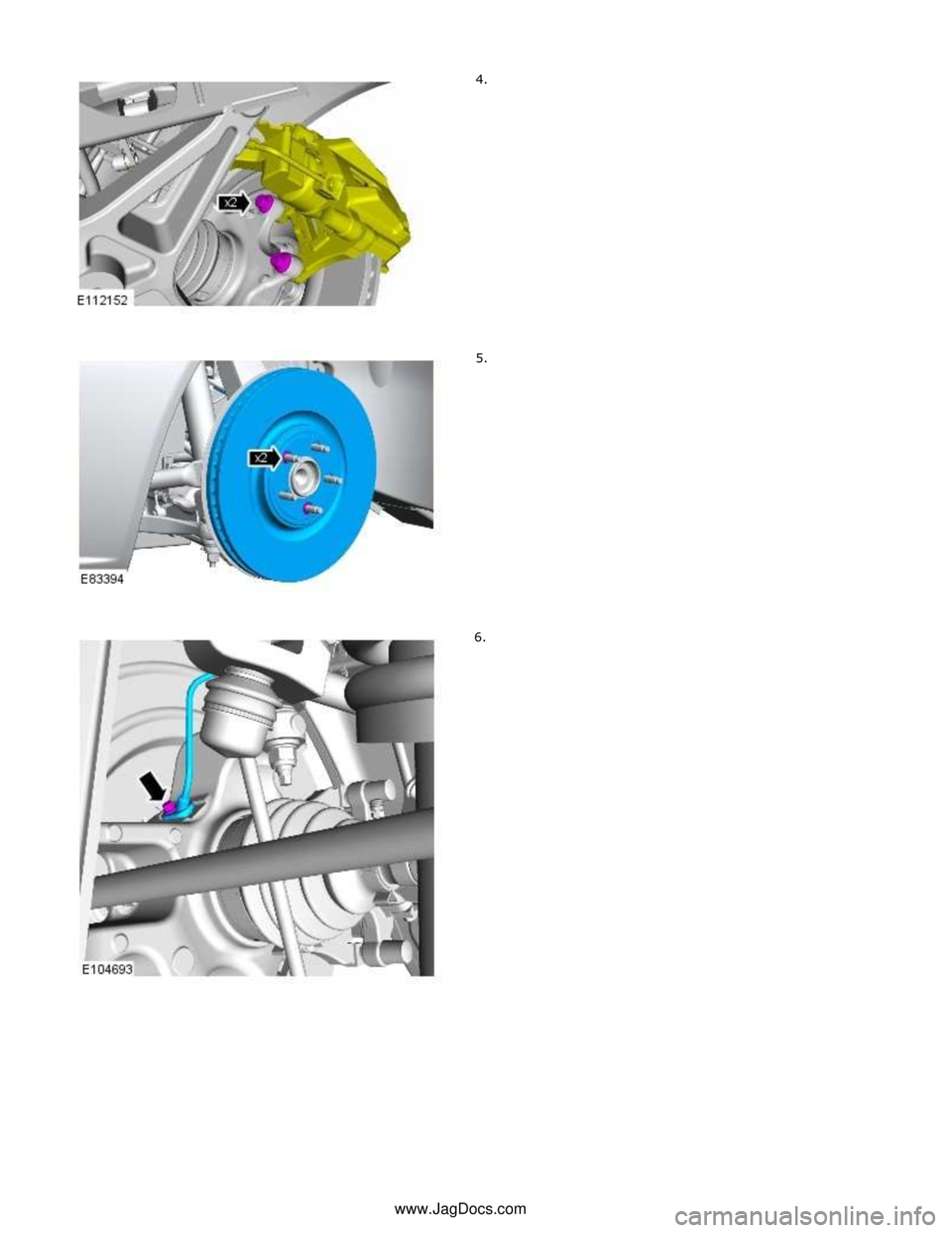
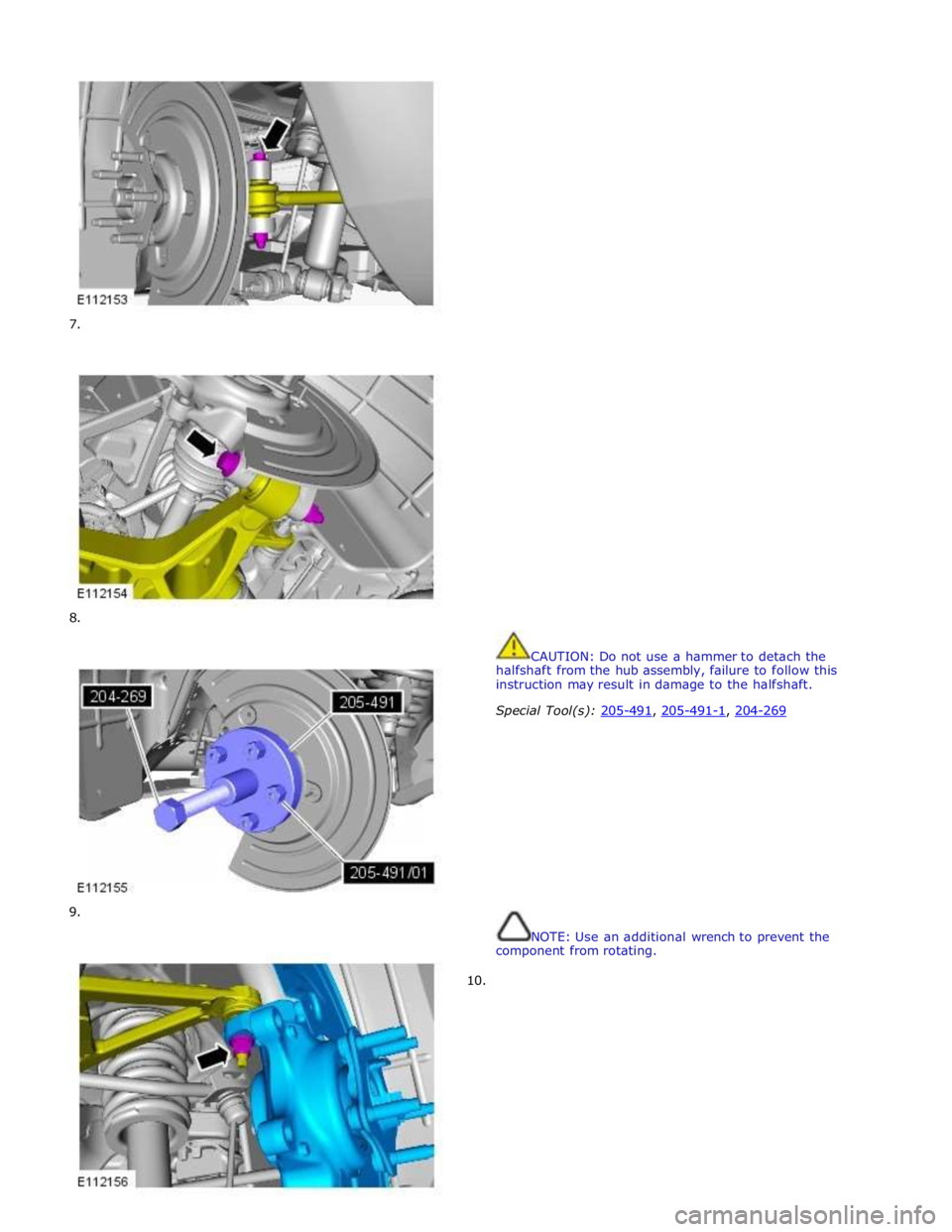
7.
8.
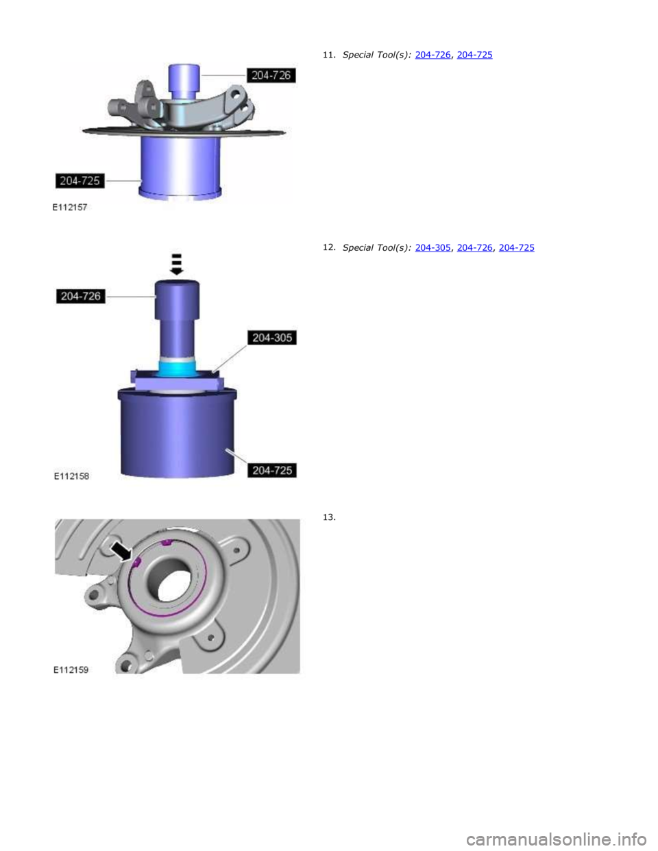
9.
10.
CAUTION: Do not use a hammer to detach the
halfshaft from the hub assembly, failure to follow this
instruction may result in damage to the halfshaft.
Special Tool(s): 205-491, 205-491-1, 204-269
NOTE: Use an additional wrench to prevent the
component from rotating.
Page 426 of 3039
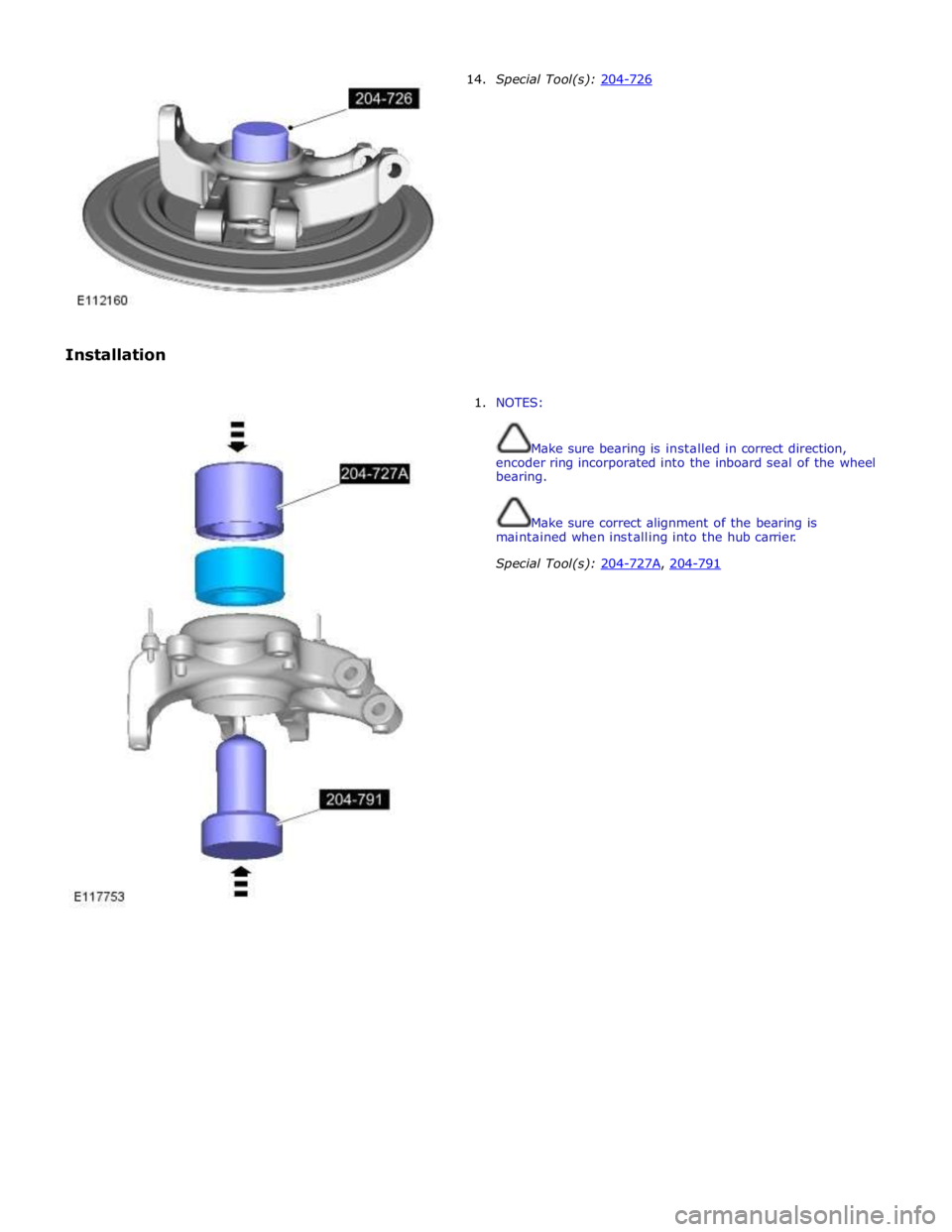
Special Tool(s): 204-305, 204-726, 204-725
Page 427 of 3039
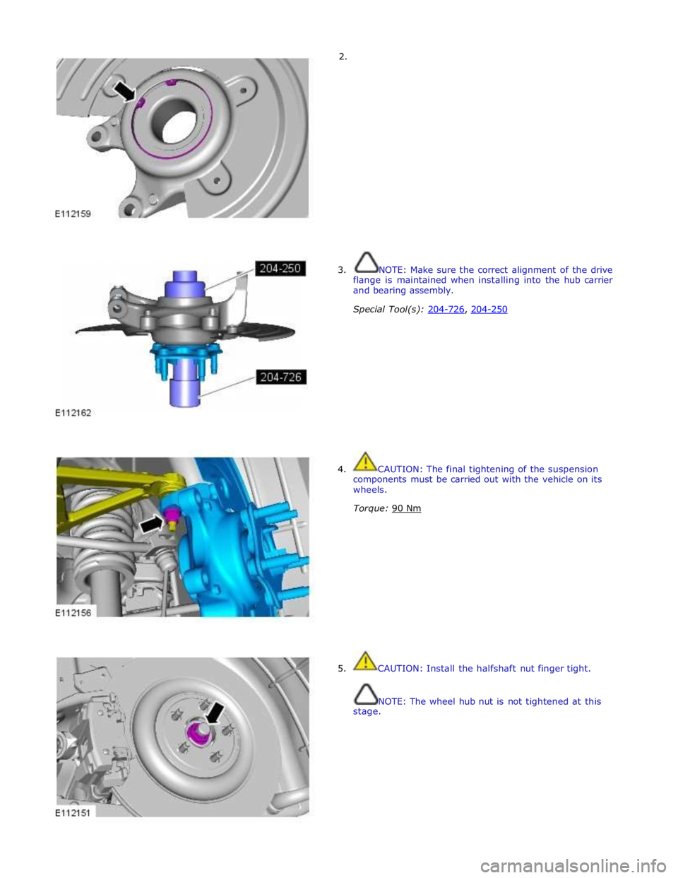
Installation 14. Special Tool(s): 204-726
1. NOTES:
Make sure bearing is installed in correct direction,
encoder ring incorporated into the inboard seal of the wheel
bearing.
Make sure correct alignment of the bearing is
maintained when installing into the hub carrier.
Special Tool(s): 204-727A, 204-791
Page 428 of 3039
2.
3. NOTE: Make sure the correct alignment of the drive
flange is maintained when installing into the hub carrier
and bearing assembly.
Special Tool(s): 204-726, 204-250
4. CAUTION: The final tightening of the suspension
components must be carried out with the vehicle on its
wheels.
Torque: 90 Nm
5. CAUTION: Install the halfshaft nut finger tight.
NOTE: The wheel hub nut is not tightened at this
stage.
Page 429 of 3039
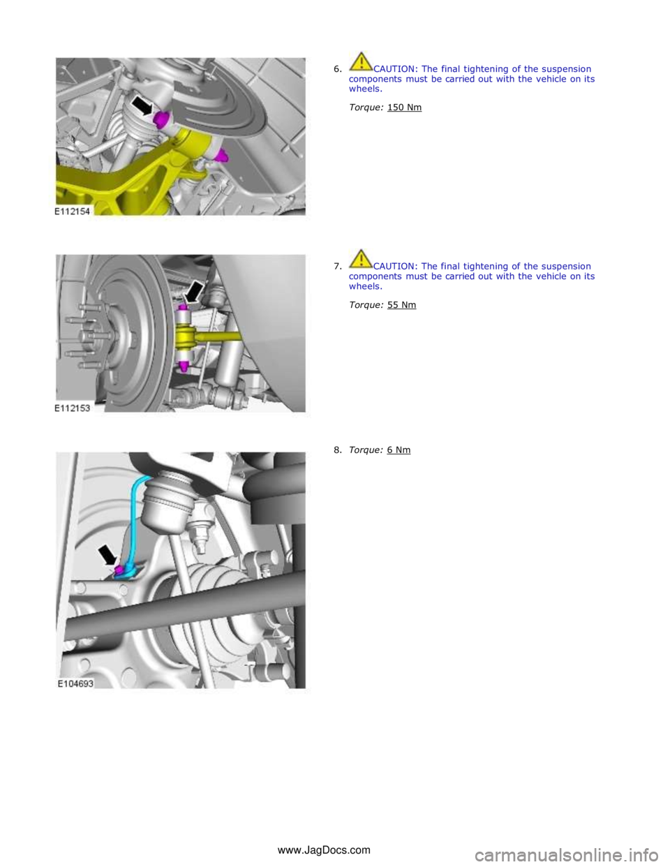
6. CAUTION: The final tightening of the suspension
components must be carried out with the vehicle on its
wheels.
Torque: 150 Nm
7. CAUTION: The final tightening of the suspension
components must be carried out with the vehicle on its
wheels.
Torque: 55 Nm
8. Torque: 6 Nm www.JagDocs.com
Page 430 of 3039
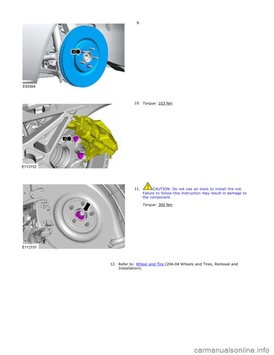
9.
10.
11.
Torque: 103 Nm
CAUTION: Do not use air tools to install the nut.
Failure to follow this instruction may result in damage to
the component.
Torque: 300 Nm
12. Refer to: Wheel and Tire (204-04 Wheels and Tires, Removal and Installation).
Trending: tire pressure reset, B111E-15, coolant pump, heater, B102B, manual transmission, auxiliary battery
