JAGUAR XFR 2010 1.G Workshop Manual
XFR 2010 1.G
JAGUAR
JAGUAR
https://www.carmanualsonline.info/img/21/7642/w960_7642-0.png
JAGUAR XFR 2010 1.G Workshop Manual
Page 2154 of 3039

Check the "Loading" button on the navigation diagnostics screen (PIN code 660) has been pressed, and "YES" has been selected. Has the "Loading" button on the navigation diagnostics screen been pressed, and has "YES" been selected? Yes
Check the correct map disc is inserted into the Navigation Control Module (NCM). Start the engine and
allow to idle for 15 minutesTurn the engine 'OFF', and then start the engine again.
No
Refer to electrical circuit diagrams and check integrity of navigation system wiring harness and
connectors.
GO to I4. I4: SYSTEM CHECK FOR DTCS 1 Check the system for DTCs which may be logged. Is DTC U300055 logged? Yes
Using the manufacturer approved diagnostic system check/amend the Car Configuration File parameter in
block 2, byte 127 to match vehicle market/specification. If the DTC remains check navigation system
module part number and ensure the correct component is installed to vehicle market/specification.
No
GO to I5. I5: NO RESPONSE TO PRESSING NAVIGATION MENU 1 Turn the engine 'OFF', wait for a moment, and then turn the engine 'ON' again. Does the navigation screen fail to display even if the navigation button is pressed? Yes
Check the HLDF is installed correctly.
Check the Navigation Control Module (NCM) is installed correctly.
No
Operation is normal. DTC Index
For a list of Diagnostic Trouble Codes (DTCs) that could be logged on this vehicle, please refer to Section 100-00.
REFER to: Diagnostic Trouble Code (DTC) Index - DTC: Navigation Control Module (NCM) (100-00, Description and Operation).
Page 2157 of 3039
(414-01 Battery, Mounting and Cables, General Procedures).
2. Remove the LH luggage compartment side trim panel.
For additional information, refer to: Loadspace Trim Panel LH (501-05 Interior Trim and Ornamentation, Removal and Installation).
3. Release the navigation system module.
4. Remove the navigation system module.
Installation
1. Install is the reverse of removal.
Page 2160 of 3039
5. Remove the bluetooth module.
Installation
1. Install is the reverse of removal.
Tighten to 10 Nm. www.JagDocs.com
Page 2161 of 3039
Rear electronic module retaining bolts 10 7 89 Multifunction voice activated module retaining bolts 10 7 89 Front electronic module retaining bolts 10 7 89
Page 2162 of 3039
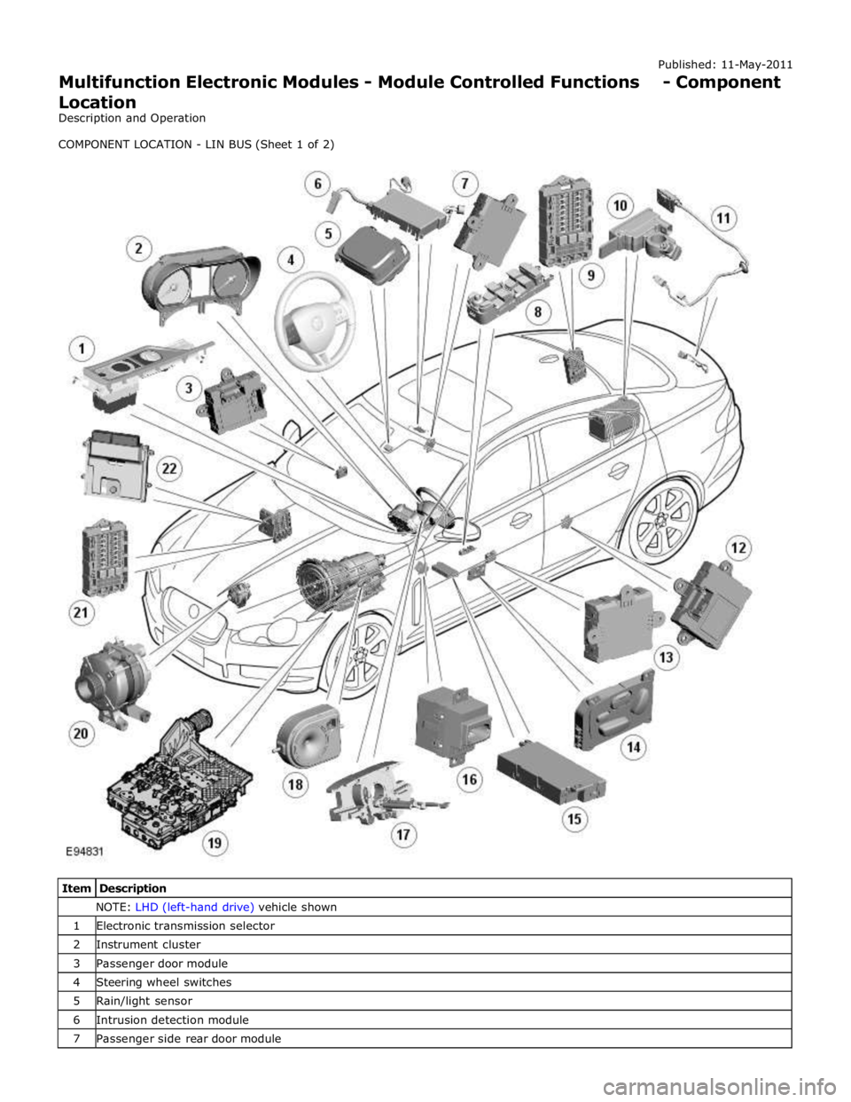
NOTE: LHD (left-hand drive) vehicle shown 1 Electronic transmission selector 2 Instrument cluster 3 Passenger door module 4 Steering wheel switches 5 Rain/light sensor 6 Intrusion detection module 7 Passenger side rear door module
Page 2163 of 3039
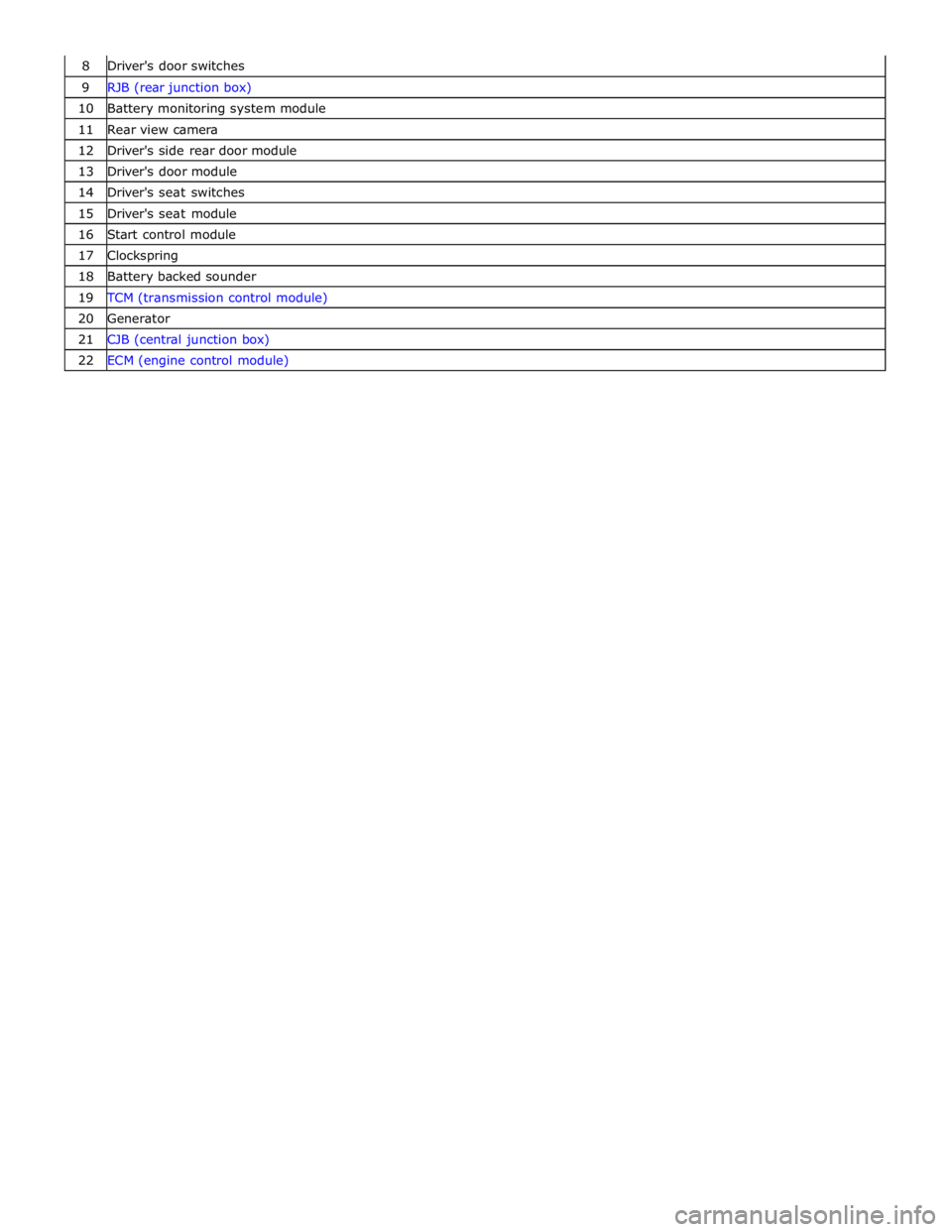
9 RJB (rear junction box) 10 Battery monitoring system module 11 Rear view camera 12 Driver's side rear door module 13 Driver's door module 14 Driver's seat switches 15 Driver's seat module 16 Start control module 17 Clockspring 18 Battery backed sounder 19 TCM (transmission control module) 20 Generator 21 CJB (central junction box) 22 ECM (engine control module)
Page 2164 of 3039
NOTE: LHD vehicle shown 1 ATC (automatic temperature control) module 2 RH (right-hand) outer face level vent 3 RH inner face level vent 4 LH (left-hand) inner face level vent 5 LH outer face level vent 6 Electric booster heater 7 Stepper motor - LH temperature blend 8 Stepper motor - windshield defrost 9 Stepper motor - RH temperature blend 10 Stepper motor - face/feet COMPONENT LOCATION - LIN BUS (Sheet 2 of 2)
Page 2165 of 3039
NOTE: LHD vehicle shown 1 CJB 2 ATC module 3 Passenger door module 4 Audio system control panel 5 Instrument cluster 6 RJB 7 RH blind spot monitoring module 8 Parking aid module 9 Keyless vehicle module 10 LH blind spot monitoring module 11 Driver's door module 12 Driver's seat module 13 Diagnostic socket COMPONENT LOCATION - MEDIUM SPEED CAN BUS
www.JagDocs.com
Page 2166 of 3039
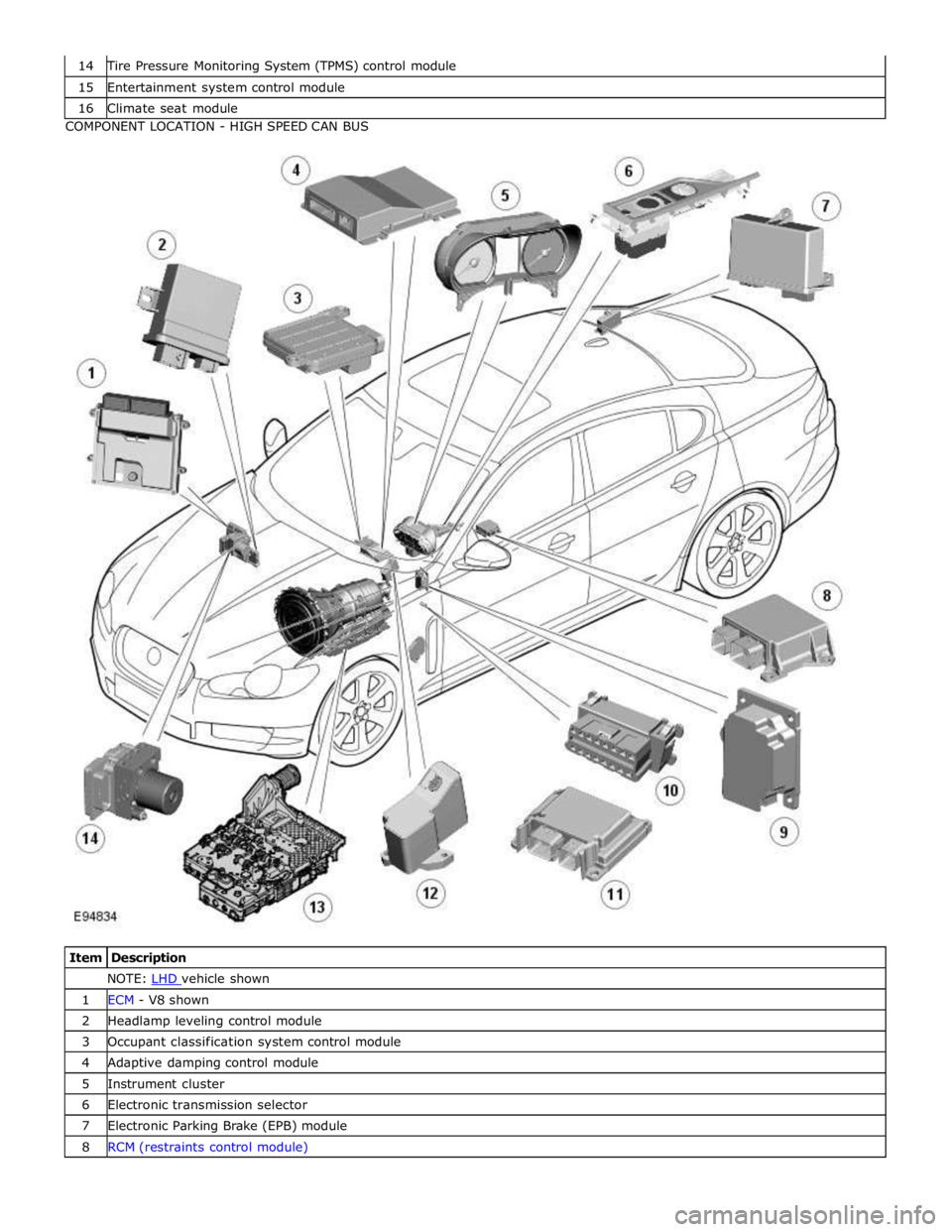
Tire Pressure Monitoring System (TPMS) control module 15 Entertainment system control module 16 Climate seat module COMPONENT LOCATION - HIGH SPEED CAN BUS
Item Description NOTE: LHD vehicle shown 1 ECM - V8 shown 2 Headlamp leveling control module 3 Occupant classification system control module 4 Adaptive damping control module 5 Instrument cluster 6 Electronic transmission selector 7 Electronic Parking Brake (EPB) module 8 RCM (restraints control module)
Page 2167 of 3039
10 Diagnostic socket 11 Pedestrian protection control module 12 Electric steering column lock 13 TCM 14 ABS (anti-lock brake system) module COMPONENT LOCATION - MOST
Item Description NOTE: LHD vehicle shown 1 Touch Screen Display (TSD) 2 Integrated audio module 3 Entertainment system control module 4 Digital Audio Broadcast (DAB)/Satellite Digital Audio Radio System (SDARS) 5 Multimedia module


