key JAGUAR XFR 2010 1.G Repair Manual
[x] Cancel search | Manufacturer: JAGUAR, Model Year: 2010, Model line: XFR, Model: JAGUAR XFR 2010 1.GPages: 3039, PDF Size: 58.49 MB
Page 1873 of 3039

Published: 02-Apr-2014
Battery and Charging System - General Information - Battery Report Form – In Service Batteries Only
Description and Operation
NOTE: Fields marked with * are mandatory and must be completed.
General Information *Vehicle Identification Number (VIN):
Vehicle
Model: Engine type: *Mileage:
*Repair
Date: - Customer Questions *1: What is the customer’s reason for dealer visit? (tick symptoms as appropriate) Non crank
Crank but non
start Warning message Other: *2: How long was the vehicle left prior to issue. * *3: How was the car left (Locked/unlocked) * *4: How did you access to the vehicle Key fob Manual key Handle pull *5: Has the vehicle required assistance for battery issues previously? Yes No *6: Is the vehicle used? (tick symptoms as appropriate) Daily
Every other day Weekly
Less than weekly *7: Average journey length * *8: How many starts do you typically do in a day * *9: Did the customer see any instrument pack warnings prior to the
issue? * *10: Have any of the features been used
without the engine running in the last 3 days (if fitted?) Radio
Power point
accessory CD DVD USB or IPOD
connection TV
Rear seat
entertainment 11: Customer comments:- Please add any additional comments that
are relevant. * Diagnostics (Battery Testing) - - - - 1: Loose battery clamps Yes * No * 2: Loose hold down clamps Yes * No * 3: Corroded terminal posts Yes * No * 4: Physical damage/leaks Yes No * 5: Low electrolyte (Flooded batteries only) Yes * No * 6: Battery Date Code * 7: FEAD belt tension OK * Not OK * 8: Quiescent Drain mA * 9: Vent tube correctly installed Yes * No * 10: Number of Times Battery Charged: * 10: Vent tube correctly installed Yes No 11: Remove the Surface (414-00 battery care requirements) Yes * No * 12: Battery voltage * 13: Midtronics test code before charging (EXP-1080) * 13a: If Midtronics indicates that the battery needs re-charging, charge
the battery following instructions on the recommended battery charger * 13b: Midtronics test code after charge * 13c: Midtronics test code result after charge * 13d: If "good and re-charge" charge the battery following instructions
on the recommended battery charger * 13e: If "charge and re-test" for both before and after the charge
renew the battery * 13f: Only renew the battery if "renew battery", "bad cell" or charge
and re-test has been displayed twice. * Technician Comments:- Please add any additional comments that are relevant. * * * * *
Page 1891 of 3039

1 LCD screen with main menu 2 Control panel (key board and power button) 3 Positive and negative fly leads 4 Fly leads connection 5 Temperature sensor 6 Infra-red sensor (data transfer for printer) 7 Amp hour 8 Battery rating (CCA) 9 Rating units 10 Battery type
clean clamp and terminal then reconnect and repeat test GO to A2.
Page 1893 of 3039

NOTE: BATTERY LOCATION
5. Battery Location
Select Next
6. VIN. When IN VEHICLE selected, enter the last six of the VIN using the key pad
Page 1895 of 3039

NOTE:
BATTERY
RATING
9.
BATTERY
RATING.
Scroll
using
the
arrow
keys
on
the
midtronics
panel,
select
the
correct
CCA
rating
(For
CCA
refer
to
battery
label)
Select
Next
NOTE:BATTERYTYPE
8.BatteryUnits.Selectthecorrectbatteryratingfromthebatterylabelinbrackets(number9).Scrollusingthearrow
ontheMidtronicspanelandselectNext
NOTE:UNITS
Page 1899 of 3039
Battery
test
code,
must
be
given if
a
battery,
starter
motor
or
generator
is
exchanged
under
warranty
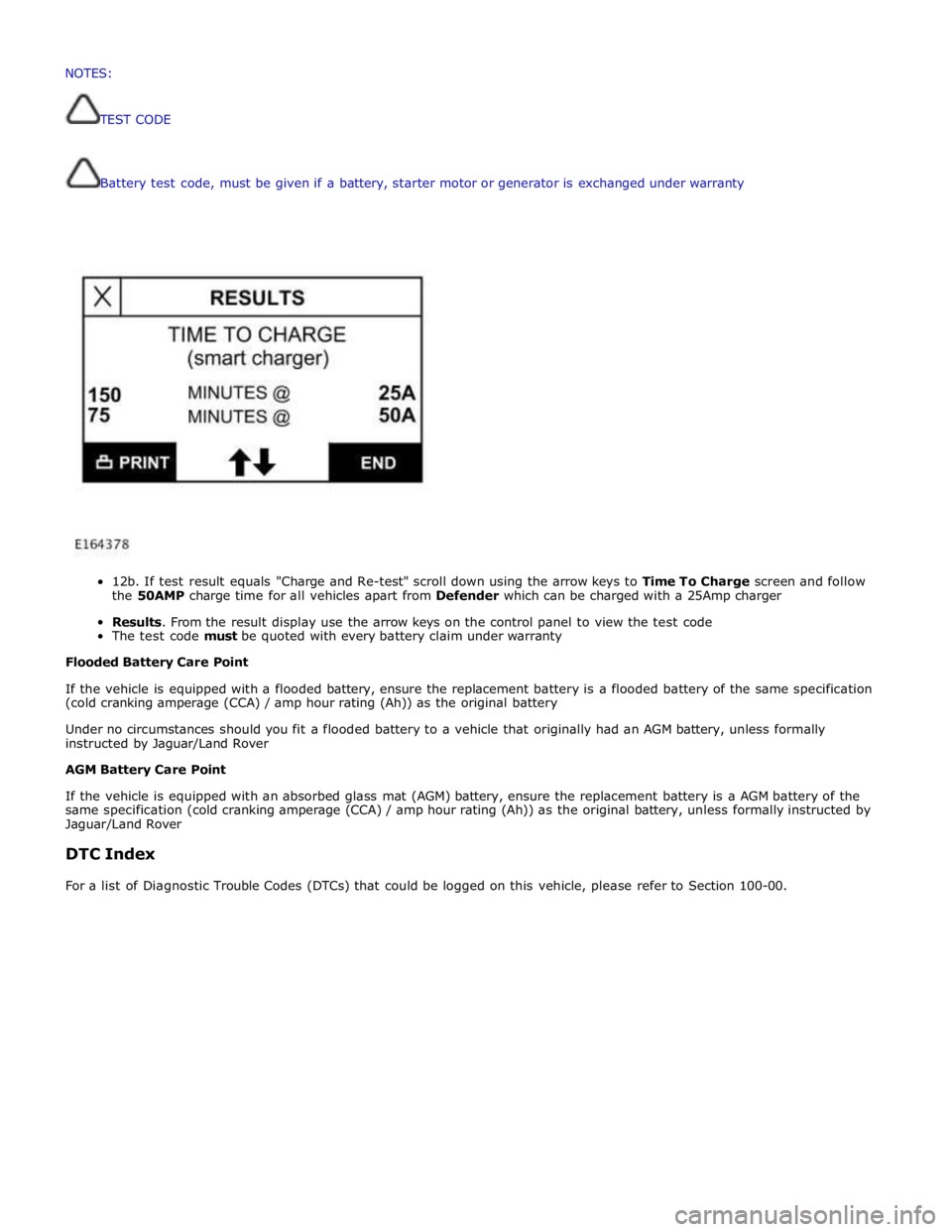
12b.
If
test
result
equals
"Charge
and
Re-test"
scroll
down
using
the
arrow
keys
to
Time To
Charge
screen and follow
the
50AMP
charge
time
for
all
vehicles
apart
from
Defender
which
can
be
charged
with a
25Amp
charger
Results.
From
the
result
display
use
the
arrow
keys
on
the
control
panel
to
view the
test
code
The
test
code
must
be
quoted
with every
battery
claim
under
warranty
Flooded
Battery
Care
Point
If
the
vehicle
is
equipped with
a
flooded
battery,
ensure
the
replacement
battery
is
a
flooded
battery
of
the
same
specification
(cold
cranking
amperage
(CCA)
/ amp
hour
rating
(Ah))
as
the
original
battery
Under
no
circumstances
should you
fit
a
flooded
battery
to a
vehicle
that
originally
had
an
AGM
battery,
unless
formally
instructed
by Jaguar/Land
Rover
AGM
Battery
Care
Point
If
the
vehicle
is
equipped with
an absorbed
glass
mat
(AGM)
battery,
ensure
the
replacement
battery
is
a
AGM
battery
of
the
same
specification
(cold
cranking
amperage
(CCA)
/
amp
hour
rating
(Ah))
as
the
original
battery,
unless
formally
instructed
by
Jaguar/Land
Rover
DTC
Index
For
a
list
of
Diagnostic
Trouble
Codes
(DTCs)
that
could
be
logged
on
this
vehicle,
please
refer
to
Section
100-00. NOTES:
TESTCODE
Page 1966 of 3039

Publi s hed: 11-May-2011
Information and Entertainment System - Cellular Phone - Overview
Des cript ion and Operat ion
Authori ng Templat e
OVERVIEW
The cel lul ar phone s yst em us es t he cus t omers own Bluetooth® capabl e hands et in conjuncti on wit h t he vehicle
informat ion and ent ertai nment sys tem. The t elephone cont rol module i s l ocated under t he left -hand front s eat, and has a
Bluet oot h® ant enna integrat ed i nt o t he unit . Tel ephone handset s mus t be paired wit h t he t el ephone control modul e,
requiring i nput of a PIN (pers onal i dent ificati on number) before t hey can be us ed wi th the vehicle sys tem. Once pai red, any
phone can be docked to the car wi thout re-ent eri ng a PIN (pers onal identi fi cat ion number). In addit ion t o t hi s , the l ast
connected device wi ll dock aut omati cal ly t he next ti me i t is pl aced i n t he vehi cl e a nd t he ignit ion i s i n power mode
(ignit ion on).
The s ys t em has t he abil it y to pai r and dock t elephone hands ets from t he tel ephones t hems elves . By s uppl yi ng a fixed PIN
(personal identi fi cat ion number), a us er wil l be abl e t o us e t hei r tel ephone or othe r t el ephone related Bluetooth® device
and pair wi th i t wit hout us i ng the touch s creen. This enables devices s uch as Blackberry's and ot her s ecure PDA's (pers onal
digit al ass i st ants ) t o pair and dock wit h t he vehi cl e s ys t em.
Up t o 5 telephone hands ets can be pai red wi th the vehicle, but only 1 tel ephone can be us ed at a t ime. The Touch-screen
dis plays phone functi onali ty, i ncl udi ng diali ng, and (if compati ble) t he hands et’s phone book. The Touch-s creen als o
dis plays t he phone's si gnal s trengt h and bat tery meter (if s upported by the phone). These functi ons al low the us er to vi ew
t he dis plays on t he Touch-s creen and not have to us e the handset .
• NOTE: There i s no physi cal connecti on (cradl e) bet ween t he phone hands et and the t elephone cont rol module.
Communicati ons bet ween t he 2 component s are purely Bl uet oot h®. This can l imi t t he avai lable funct ions dependant on
t he hands et used.
The s ys t em al lows t he dri ver t o make, receive and end phone cal ls us ing the Touch-s creen, s t eering wheel s wit ches and
voice recogni ti on s yst em (if fit t ed).
Phone di ali ng is achieved usi ng one of the foll owing met hods :
Dial ing a number us ing t he Touch-screen keypadSelecti ng a number from t he hands ets (aut omat icall y or manual ly downl oaded) phonebook on the Touch-s creenSelecti ng a number from t he hands ets (aut omat icall y or manual ly downl oaded) phonebook in t he i ns t rument clus ter
mes s age centerSelecti ng from t he hands et s (downloaded) cal l regis ter, typicall y the las t 10 cal ls made, received and mis s edThe t el ephone control modul e is connect ed t o t he informati on and entertainment s ys te m on the MOST (medi a oriented
s ys t ems t rans port) ring. This al lows audio and control si gnal s t o be rout ed t o and from t he t elephone control modul e.
Page 1970 of 3039
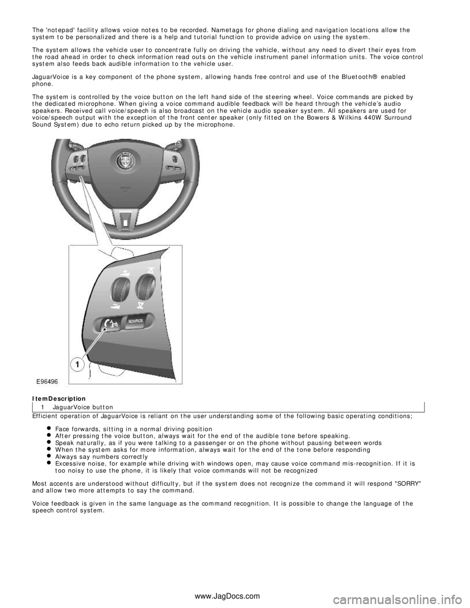
1 The 'not epad' facil it y allows voi ce not es t o be recorded. Nametags for phone di al ing and navigati on locati ons allow the
s ys t em t o be personali zed and there is a hel p and t utori al funct ion to provi de advi ce on us ing t he s ys t em.
The s ys t em al lows t he vehi cl e us er to concent rat e ful ly on drivi ng the vehicle, wi thout any need to di vert t hei r eyes from
t he road ahead in order to check informat ion read out s on t he vehi cle i nst rument panel i nformati on uni ts . The voice control
s ys t em al so feeds back audibl e informat ion t o t he vehi cle us er.
JaguarVoi ce is a key component of t he phone sys tem, al lowi ng hands free control and us e of t he Bluet oot h® enabled
phone.
The s ys t em i s cont rol led by t he voice butt on on t he left hand si de of the st eeri ng wheel . Voi ce commands are pi cked by
t he dedi cat ed mi crophone. W hen givi ng a voice command audible feedback wi ll be heard t hrough t he vehi cl e’s audio
s peakers . Recei ved cal l voice/speech is al so broadcas t on t he vehi cl e audio s peaker s yst em. All s peakers are us ed for
voice/s peech out put wi th the except ion of t he front cent er speaker (only fit ted on t he Bowers & W il ki ns 440W Surround
Sound Sys t em) due to echo return picked up by t he microphone.ItemDescription
JaguarVoice butt on
Efficient operati on of JaguarVoice i s rel iant on t he us er unders t anding some of the foll owi ng basi c operati ng condi ti ons ;
Face forwards, s i tt ing i n a normal driving pos it ionAft er pres si ng t he voi ce but t on, al ways wai t for t he end of the audibl e t one before s peaki ng.Speak nat urall y, as if you were tal ki ng to a pas senger or on the phone wi thout paus i ng bet ween wordsW hen t he s yst em as ks for more i nformati on, always wai t for t he end of the t one before res pondi ngAlways s ay numbers correct lyExces s ive nois e, for example whi le driving wit h windows open, may caus e voice command mis -recognit ion. If i t is
t oo noi s y to use the phone, it is li kel y that voice commands wil l not be recogni zedMos t accents are unders tood wi thout diffi cult y, but if t he sys t em does not recogni ze the command i t wil l res pond "SORRY "
and all ow t wo more att empts to say t he command.
Voice feedback is gi ven in t he s ame l anguage as t he command recogni ti on. It is pos s i bl e to change t he language of t he
s peech control s ys tem.
www.JagDocs.com
Page 1981 of 3039
Navigation Destination, stored locations, navigation setup, route options Vehicle
Security, parking, valet mode, trip computer, clock, brightness, contrast, system settings, vehicle settings, display settings The screen is a touch sensitive 7 inch LCD (liquid crystal display) VGA screen containing 800 x 480 pixels in a 15:9 format. The
screen processes its own video for system operation but receives the navigation graphics from the navigation computer.
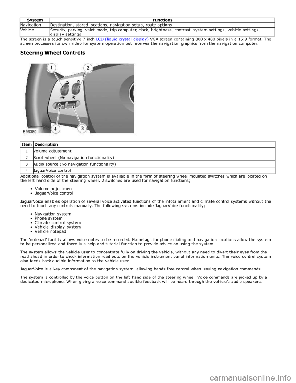
Steering Wheel Controls
Item Description 1 Volume adjustment 2 Scroll wheel (No navigation functionality) 3 Audio source (No navigation functionality) 4 JaguarVoice control Additional control of the navigation system is available in the form of steering wheel mounted switches which are located on
the left hand side of the steering wheel. 2 switches are used for navigation functions;
Volume adjustment
JaguarVoice control
JaguarVoice enables operation of several voice activated functions of the infotainment and climate control systems without the
need to touch any controls manually. The following systems include JaguarVoice functionality;
Navigation system
Phone system
Climate control system
Vehicle display system
Vehicle notepad
The 'notepad' facility allows voice notes to be recorded. Nametags for phone dialing and navigation locations allow the system
to be personalized and there is a help and tutorial function to provide advice on using the system.
The system allows the vehicle user to concentrate fully on driving the vehicle, without any need to divert their eyes from the
road ahead in order to check information read outs on the vehicle instrument panel information units. The voice control system
also feeds back audible information to the vehicle user.
JaguarVoice is a key component of the navigation system, allowing hands free control when issuing navigation commands.
The system is controlled by the voice button on the left hand side of the steering wheel. Voice commands are picked up by a
dedicated microphone. When giving a voice command audible feedback will be heard through the vehicle’s audio speakers.
Page 2032 of 3039
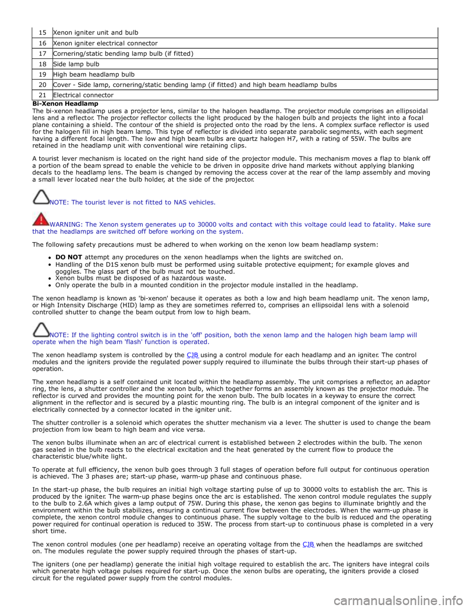
15 Xenon igniter unit and bulb 16 Xenon igniter electrical connector 17 Cornering/static bending lamp bulb (if fitted) 18 Side lamp bulb 19 High beam headlamp bulb 20 Cover - Side lamp, cornering/static bending lamp (if fitted) and high beam headlamp bulbs 21 Electrical connector Bi-Xenon Headlamp
The bi-xenon headlamp uses a projector lens, similar to the halogen headlamp. The projector module comprises an ellipsoidal
lens and a reflector. The projector reflector collects the light produced by the halogen bulb and projects the light into a focal
plane containing a shield. The contour of the shield is projected onto the road by the lens. A complex surface reflector is used
for the halogen fill in high beam lamp. This type of reflector is divided into separate parabolic segments, with each segment
having a different focal length. The low and high beam bulbs are quartz halogen H7, with a rating of 55W. The bulbs are
retained in the headlamp unit with conventional wire retaining clips.
A tourist lever mechanism is located on the right hand side of the projector module. This mechanism moves a flap to blank off
a portion of the beam spread to enable the vehicle to be driven in opposite drive hand markets without applying blanking
decals to the headlamp lens. The beam is changed by removing the access cover at the rear of the lamp assembly and moving
a small lever located near the bulb holder, at the side of the projector.
NOTE: The tourist lever is not fitted to NAS vehicles.
WARNING: The Xenon system generates up to 30000 volts and contact with this voltage could lead to fatality. Make sure
that the headlamps are switched off before working on the system.
The following safety precautions must be adhered to when working on the xenon low beam headlamp system:
DO NOT attempt any procedures on the xenon headlamps when the lights are switched on.
Handling of the D1S xenon bulb must be performed using suitable protective equipment; for example gloves and
goggles. The glass part of the bulb must not be touched.
Xenon bulbs must be disposed of as hazardous waste.
Only operate the bulb in a mounted condition in the projector module installed in the headlamp.
The xenon headlamp is known as 'bi-xenon' because it operates as both a low and high beam headlamp unit. The xenon lamp,
or High Intensity Discharge (HID) lamp as they are sometimes referred to, comprises an ellipsoidal lens with a solenoid
controlled shutter to change the beam output from low to high beam.
NOTE: If the lighting control switch is in the 'off' position, both the xenon lamp and the halogen high beam lamp will
operate when the high beam 'flash' function is operated.
The xenon headlamp system is controlled by the CJB using a control module for each headlamp and an igniter. The control modules and the igniters provide the regulated power supply required to illuminate the bulbs through their start-up phases of
operation.
The xenon headlamp is a self contained unit located within the headlamp assembly. The unit comprises a reflector, an adaptor
ring, the lens, a shutter controller and the xenon bulb, which together forms an assembly known as the projector module. The
reflector is curved and provides the mounting point for the xenon bulb. The bulb locates in a keyway to ensure the correct
alignment in the reflector and is secured by a plastic mounting ring. The bulb is an integral component of the igniter and is
electrically connected by a connector located in the igniter unit.
The shutter controller is a solenoid which operates the shutter mechanism via a lever. The shutter is used to change the beam
projection from low beam to high beam and vice versa.
The xenon bulbs illuminate when an arc of electrical current is established between 2 electrodes within the bulb. The xenon
gas sealed in the bulb reacts to the electrical excitation and the heat generated by the current flow to produce the
characteristic blue/white light.
To operate at full efficiency, the xenon bulb goes through 3 full stages of operation before full output for continuous operation
is achieved. The 3 phases are; start-up phase, warm-up phase and continuous phase.
In the start-up phase, the bulb requires an initial high voltage starting pulse of up to 30000 volts to establish the arc. This is
produced by the igniter. The warm-up phase begins once the arc is established. The xenon control module regulates the supply
to the bulb to 2.6A which gives a lamp output of 75W. During this phase, the xenon gas begins to illuminate brightly and the
environment within the bulb stabilizes, ensuring a continual current flow between the electrodes. When the warm-up phase is
complete, the xenon control module changes to continuous phase. The supply voltage to the bulb is reduced and the operating
power required for continual operation is reduced to 35W. The process from start-up to continuous phase is completed in a very
short time.
The xenon control modules (one per headlamp) receive an operating voltage from the CJB when the headlamps are switched on. The modules regulate the power supply required through the phases of start-up.
The igniters (one per headlamp) generate the initial high voltage required to establish the arc. The igniters have integral coils
which generate high voltage pulses required for start-up. Once the xenon bulbs are operating, the igniters provide a closed
circuit for the regulated power supply from the control modules.
Page 2036 of 3039
Rear Fog Lamp
The rear fog lamps are located in separate units attached to the luggage compartment lid. The rear fog lamps each use 3 high
intensity LED's. The fog lamp locates in a recess in the luggage compartment lid has a seal to prevent the ingress of water into the luggage compartment. The lamp is secured in the recess with a metal securing clip. The rear fog lamp is activated
using a button located on the auxiliary lighting switch in the instrument panel.
LICENCE PLATE LAMPS
Two licence plate lamps are located in the luggage compartment lid trim finisher. One is located adjacent to the emergency
luggage compartment lid release key barrel cover and the other is adjacent to the rear view camera (if fitted). The licence plate
lamps are active at all times when the side lamps are operating. Each lamp can be removed from the finisher by inserting a
wide, flat screwdriver blade or similar tool in a slot between the lamp lens and the finisher and gently levering the lamp from
the surround. The bulb is a push fit in a holder which in turn is a press fit in the lamp housing.
HIGH MOUNTED STOP LAMP
The high mounted stop lamp is located at the bottom of the rear windshield. The lamp is secured to a bezel in the parcel shelf
with 2 screws.
The high mounted stop lamp uses 12, red colored LED's which illuminate through a clear lens. The high mounted stop lamp functionality is the same as that described for the stop lamps.
TURN SIGNAL INDICATOR SIDE REPEATER LAMPS
The turn signal indicator side repeaters are located in each door mirror. On vehicles from 10MY the lamp is an LED unit which illuminates in an orange color. The LED unit is secured to the mirror bezel with 2 screws and is connected to the mirror wiring harness with a 2 pin connector.
The side repeaters have the same functionality and operate in conjunction with the front and rear turn signal indicators and
the hazard warning flashers.
HAZARD FLASHERS
The hazard flashers are activated by a non-latching switch located in the switch pack located in the center of the instrument
panel. The hazard flashers operate at all times when selected and operate independent of the ignition mode.
When the hazard flashers are selected on by the driver, a ground path is momentarily completed to the CJB which activates the front and rear and side repeater turn signal indicators. A second press of the switch is sensed by the CJB and the hazard flasher are deactivated. When the hazard flashers are active, they override any request for turn signal indicator operation.
The hazard flashers can also be activated by a crash signal from the RCM. Refer to: Air Bag and Safety Belt Pretensioner Supplemental Restraint System (SRS) (501-20B Supplemental Restraint System, Description and Operation).