key JAGUAR XFR 2010 1.G Owner's Guide
[x] Cancel search | Manufacturer: JAGUAR, Model Year: 2010, Model line: XFR, Model: JAGUAR XFR 2010 1.GPages: 3039, PDF Size: 58.49 MB
Page 1034 of 3039

6. CAUTION: If the noted postion of the woodruff key is
at the 9 o'clock position, then a new flexplate must be
installed. If the woodruff key is in the 6 o'clock position
then proceed with the next step.
Note the position of the crankshaft woodruff key.
7.
Page 1041 of 3039
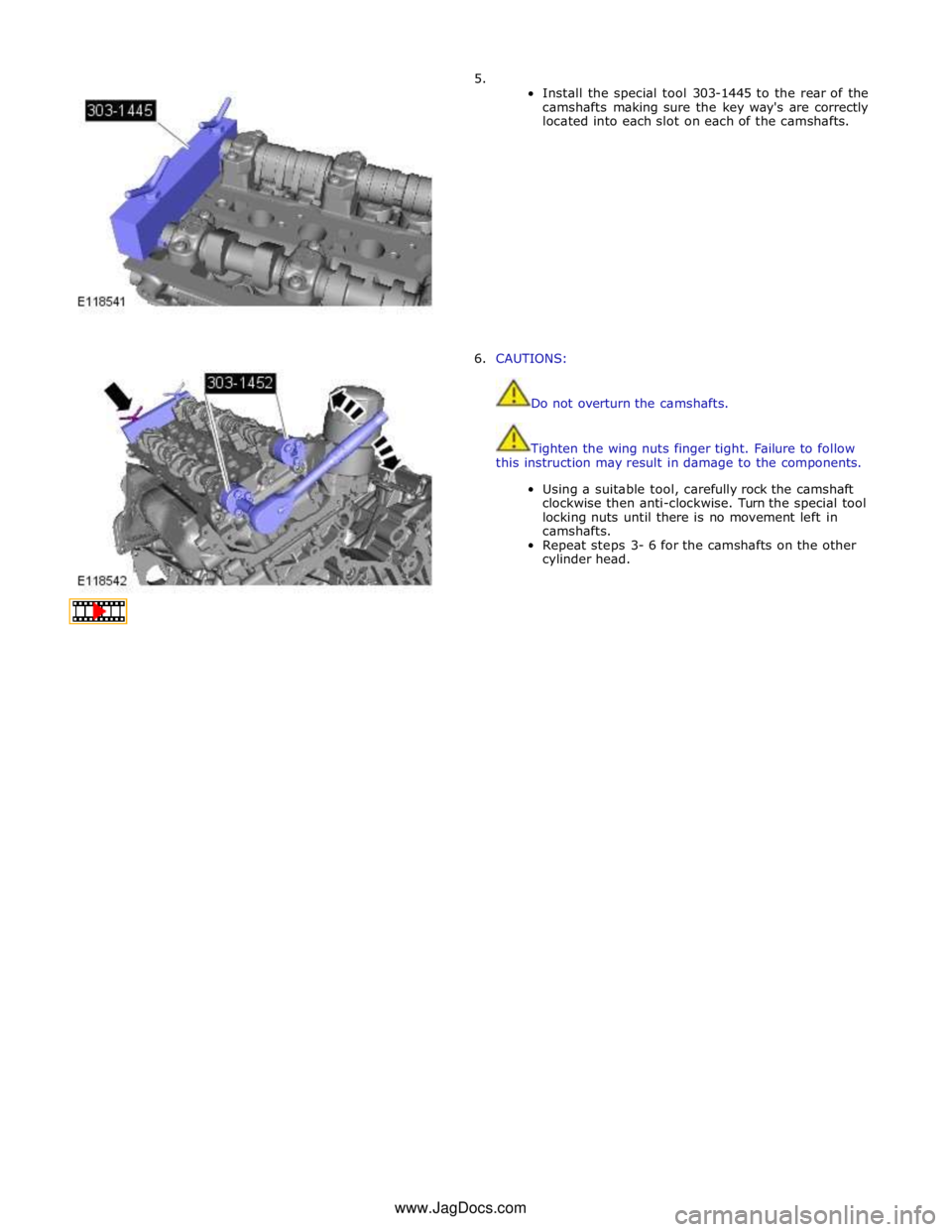
5.
Install the special tool 303-1445 to the rear of the
camshafts making sure the key way's are correctly
located into each slot on each of the camshafts.
6. CAUTIONS:
Do not overturn the camshafts.
Tighten the wing nuts finger tight. Failure to follow
this instruction may result in damage to the components.
Using a suitable tool, carefully rock the camshaft
clockwise then anti-clockwise. Turn the special tool
locking nuts until there is no movement left in
camshafts.
Repeat steps 3- 6 for the camshafts on the other
cylinder head. www.JagDocs.com
Page 1263 of 3039
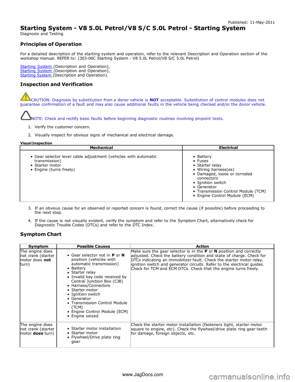
Published: 11-May-2011
Starting System - V8 5.0L Petrol/V8 S/C 5.0L Petrol - Starting System
Diagnosis and Testing
Principles of Operation
For a detailed description of the starting system and operation, refer to the relevant Description and Operation section of the
workshop manual. REFER to: (303-06C Starting System - V8 5.0L Petrol/V8 S/C 5.0L Petrol)
Starting System (Description and Operation), Starting System (Description and Operation), Starting System (Description and Operation).
Inspection and Verification
CAUTION: Diagnosis by substitution from a donor vehicle is NOT acceptable. Substitution of control modules does not
guarantee confirmation of a fault and may also cause additional faults in the vehicle being checked and/or the donor vehicle.
NOTE: Check and rectify basic faults before beginning diagnostic routines involving pinpoint tests.
1. Verify the customer concern.
2. Visually inspect for obvious signs of mechanical and electrical damage.
Visual Inspection
Mechanical Electrical
Gear selector lever cable adjustment (vehicles with automatic
transmission)
Starter motor
Engine (turns freely)
Battery
Fuses
Starter relay
Wiring harness(es)
Damaged, loose or corroded
connectors
Ignition switch
Generator
Transmission Control Module (TCM)
Engine Control Module (ECM)
3. If an obvious cause for an observed or reported concern is found, correct the cause (if possible) before proceeding to
the next step.
4. If the cause is not visually evident, verify the symptom and refer to the Symptom Chart, alternatively check for
Diagnostic Trouble Codes (DTCs) and refer to the DTC Index.
Symptom Chart
Symptom Possible Causes Action The engine does
not crank (starter
motor does not
turn)
Gear selector not in P or N
position (vehicles with
automatic transmission)
Battery
Starter relay
Invalid key code received by
Central Junction Box (CJB)
Harness/Connectors
Starter motor
Ignition switch
Generator
Transmission Control Module
(TCM)
Engine Control Module (ECM)
Engine seized Make sure the gear selector is in the P or N position and correctly
adjusted. Check the battery condition and state of charge. Check for
DTCs indicating an immobilizer fault. Check the starter motor relay,
ignition switch and generator circuits. Refer to the electrical guides.
Check for TCM and ECM DTCs. Check that the engine turns freely. The engine does
not crank (starter
motor does turn)
Starter motor installation
Starter motor
Flywheel/Drive plate ring
gear Check the starter motor installation (fasteners tight, starter motor
square to engine, etc). Check the flywheel/drive plate ring gear teeth
for damage, foreign objects, etc. www.JagDocs.com
Page 1265 of 3039
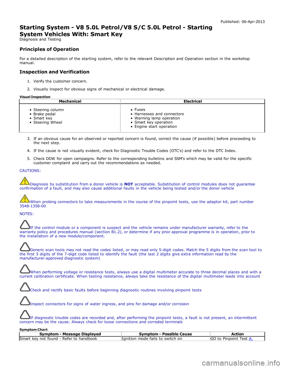
Starting System - V8 5.0L Petrol/V8 S/C 5.0L Petrol - Starting
System Vehicles With: Smart Key
Diagnosis and Testing
Principles of Operation Published: 06-Apr-2013
For a detailed description of the starting system, refer to the relevant Description and Operation section in the workshop
manual.
Inspection and Verification
1. Verify the customer concern.
2. Visually inspect for obvious signs of mechanical or electrical damage.
Visual Inspection
Mechanical Electrical
Steering column
Brake pedal
Smart key
Steering Wheel
Fuses
Harnesses and connectors
Warning lamp operation
Smart key operation
Engine start operation
3. If an obvious cause for an observed or reported concern is found, correct the cause (if possible) before proceeding to
the next step.
4. If the cause is not visually evident, check for Diagnostic Trouble Codes (DTC's) and refer to the DTC Index.
5. Check DDW for open campaigns. Refer to the corresponding bulletins and SSM's which may be valid for the specific
customer complaint and carry out the recommendations as needed.
CAUTIONS:
Diagnosis by substitution from a donor vehicle is NOT acceptable. Substitution of control modules does not guarantee
confirmation of a fault, and may also cause additional faults in the vehicle being tested and/or the donor vehicle
When probing connectors to take measurements in the course of the pinpoint tests, use the adaptor kit, part number
3548-1358-00
NOTES:
If the control module or a component is suspect and the vehicle remains under manufacturer warranty, refer to the
warranty policy and procedures manual (section B1.2), or determine if any prior approval programme is in operation, prior to
the installation of a new module/component.
Generic scan tools may not read the codes listed, or may read only 5-digit codes. Match the 5 digits from the scan tool to
the first 5 digits of the 7-digit code listed to identify the fault (the last 2 digits give extra information read by the
manufacturer-approved diagnostic system)
When performing voltage or resistance tests, always use a digital multimeter accurate to three decimal places and with a
current calibration certificate. When testing resistance, always take the resistance of the digital multimeter leads into account
Check and rectify basic faults before beginning diagnostic routines involving pinpoint tests
Inspect connectors for signs of water ingress, and pins for damage and/or corrosion
If diagnostic trouble codes are recorded and, after performing the pinpoint tests, a fault is not present, an intermittent
concern may be the cause. Always check for loose connections and corroded terminals
Symptom Chart
Symptom - Message Displayed Symptom - Possible Cause Action Smart key not found - Refer to handbook Ignition mode fails to switch on GO to Pinpoint Test A.
Page 1266 of 3039
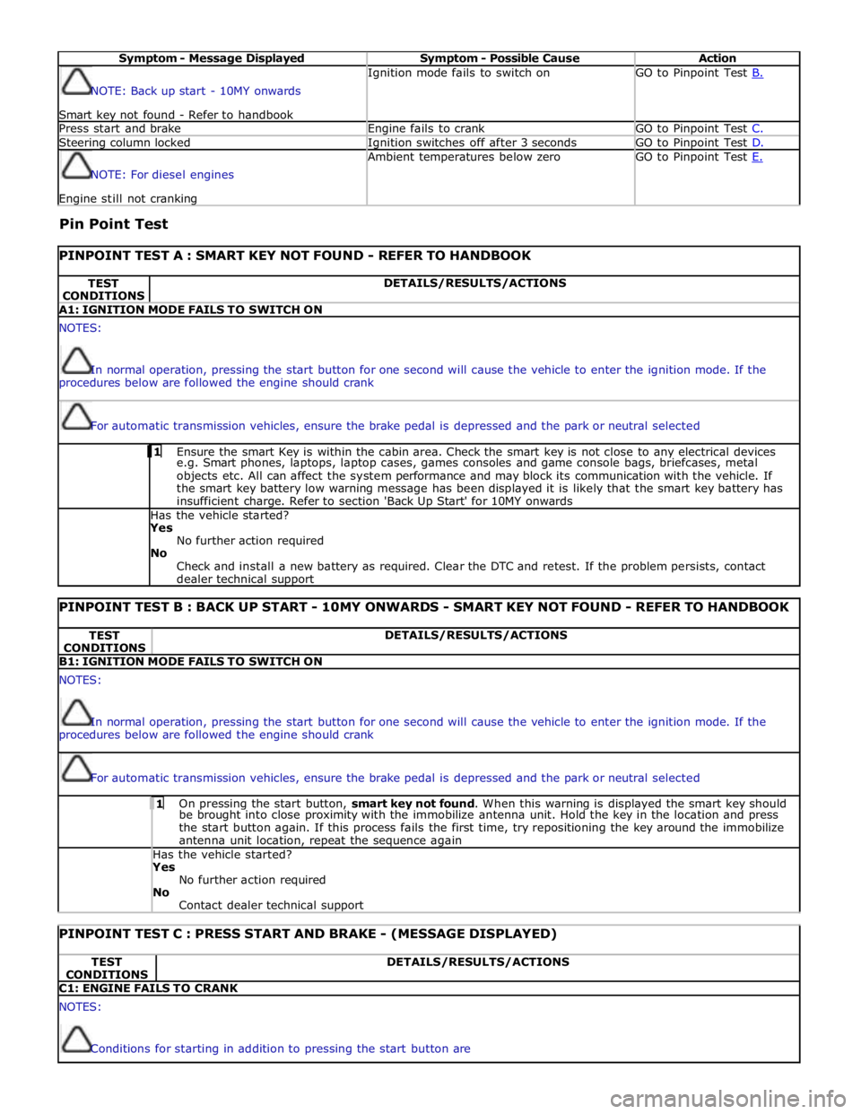
Symptom - Message Displayed Symptom - Possible Cause Action NOTE: Back up start - 10MY onwards
Smart key not found - Refer to handbook Ignition mode fails to switch on GO to Pinpoint Test B. Press start and brake Engine fails to crank GO to Pinpoint Test C. Steering column locked Ignition switches off after 3 seconds GO to Pinpoint Test D. NOTE: For diesel engines Engine still not cranking Ambient temperatures below zero GO to Pinpoint Test E.
Pin Point Test
PINPOINT TEST A : SMART KEY NOT FOUND - REFER TO HANDBOOK TEST
CONDITIONS DETAILS/RESULTS/ACTIONS A1: IGNITION MODE FAILS TO SWITCH ON NOTES:
In normal operation, pressing the start button for one second will cause the vehicle to enter the ignition mode. If the
procedures below are followed the engine should crank
For automatic transmission vehicles, ensure the brake pedal is depressed and the park or neutral selected 1 Ensure the smart Key is within the cabin area. Check the smart key is not close to any electrical devices e.g. Smart phones, laptops, laptop cases, games consoles and game console bags, briefcases, metal
objects etc. All can affect the system performance and may block its communication with the vehicle. If
the smart key battery low warning message has been displayed it is likely that the smart key battery has
insufficient charge. Refer to section 'Back Up Start' for 10MY onwards Has the vehicle started? Yes
No further action required
No
Check and install a new battery as required. Clear the DTC and retest. If the problem persists, contact
dealer technical support
PINPOINT TEST B : BACK UP START - 10MY ONWARDS - SMART KEY NOT FOUND - REFER TO HANDBOOK TEST
CONDITIONS DETAILS/RESULTS/ACTIONS B1: IGNITION MODE FAILS TO SWITCH ON NOTES:
In normal operation, pressing the start button for one second will cause the vehicle to enter the ignition mode. If the
procedures below are followed the engine should crank
For automatic transmission vehicles, ensure the brake pedal is depressed and the park or neutral selected 1 On pressing the start button, smart key not found. When this warning is displayed the smart key should be brought into close proximity with the immobilize antenna unit. Hold the key in the location and press
the start button again. If this process fails the first time, try repositioning the key around the immobilize
antenna unit location, repeat the sequence again Has the vehicle started? Yes
No further action required
No
Contact dealer technical support
PINPOINT TEST C : PRESS START AND BRAKE - (MESSAGE DISPLAYED) TEST
CONDITIONS DETAILS/RESULTS/ACTIONS C1: ENGINE FAILS TO CRANK NOTES:
Conditions for starting in addition to pressing the start button are
Page 1267 of 3039
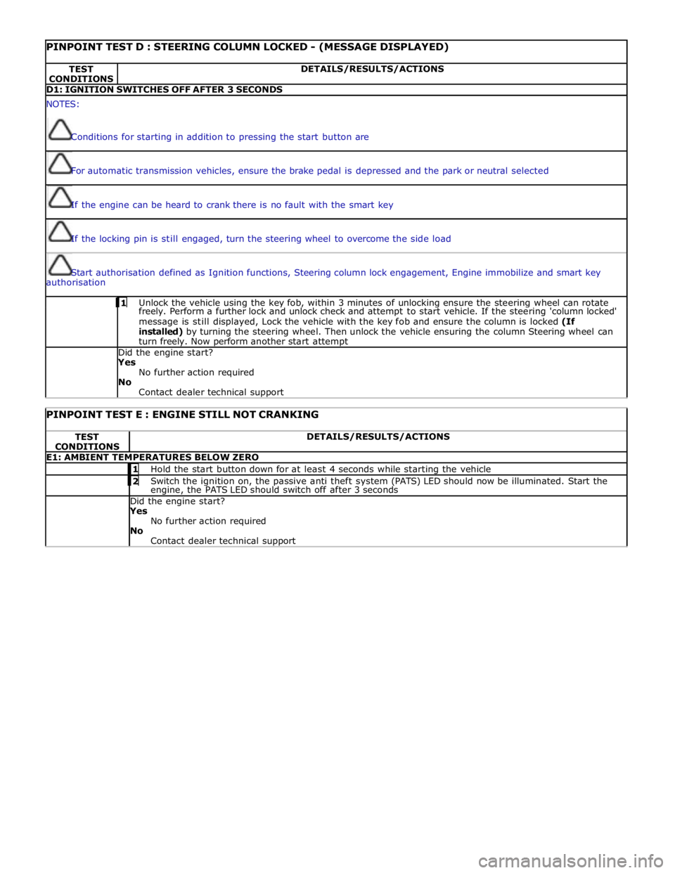
PINPOINT TEST D : STEERING COLUMN LOCKED - (MESSAGE DISPLAYED) TEST
CONDITIONS DETAILS/RESULTS/ACTIONS D1: IGNITION SWITCHES OFF AFTER 3 SECONDS NOTES:
Conditions for starting in addition to pressing the start button are
For automatic transmission vehicles, ensure the brake pedal is depressed and the park or neutral selected
If the engine can be heard to crank there is no fault with the smart key
If the locking pin is still engaged, turn the steering wheel to overcome the side load
Start authorisation defined as Ignition functions, Steering column lock engagement, Engine immobilize and smart key
authorisation 1 Unlock the vehicle using the key fob, within 3 minutes of unlocking ensure the steering wheel can rotate freely. Perform a further lock and unlock check and attempt to start vehicle. If the steering 'column locked'
message is still displayed, Lock the vehicle with the key fob and ensure the column is locked (If
installed) by turning the steering wheel. Then unlock the vehicle ensuring the column Steering wheel can
turn freely. Now perform another start attempt Did the engine start?
Yes
No further action required
No
Contact dealer technical support
PINPOINT TEST E : ENGINE STILL NOT CRANKING TEST
CONDITIONS DETAILS/RESULTS/ACTIONS E1: AMBIENT TEMPERATURES BELOW ZERO 1 Hold the start button down for at least 4 seconds while starting the vehicle 2 Switch the ignition on, the passive anti theft system (PATS) LED should now be illuminated. Start the engine, the PATS LED should switch off after 3 seconds Did the engine start? Yes
No further action required
No
Contact dealer technical support
Page 1413 of 3039

Ration 4.171 2.340 1.521 1.143 0.867 0.691 3.403 Shift Elements
Item Description 1 Turbine shaft 2 Stator shaft 3 Single web planetary gear train 4 Ring gear 1 5 Clutch A 6 Clutch B 7 Clutch E 8 Brake clutch C 9 Fixed connection to transmission housing 10 Shaft key 11 Brake clutch D 12 Double web planetary gear train 13 Planetary gears - long 14 Ring gear 2 15 Sunwheel 2 16 Sunwheel 3 17 Double web planetary gear carrier 18 Planetary gears - short 19 Single web planetary gear carrier 20 Sunwheel 1 The shift elements are three rotating multiplate clutches (A, B and E) and two fixed multiplate brakes (C and D). All shifts
from 1st to 6th gears are power-on overlapping shifts. Overlapping shifts can be described as one of the clutches continuing to
transmit drive at a lower main pressure until the next required clutch is able to accept the input torque.
The shift elements, clutches and brakes are actuated hydraulically. Fluid pressure is applied to the required clutch and/or brake,
pressing the plates together and allowing drive to be transmitted through the plates. The purpose of the shift elements
is to perform power-on shifts with no interruption to traction and smooth transition between gear ratios.
Page 1414 of 3039

The JaguarDrive selector and the selector valve spool are in the 'D' position. Engine torque is transmitted from the torque
converter turbine shaft to the ring gear 1 of the single web planetary gear train and the outer plate carrier of clutch 'E'.
Ring gear 1 drives the planetary gears which rotate around sunwheel 1. This drives the planetary gear carrier 1 and also the
outer plate carrier of clutch 'A' and the inner plate carrier of clutch 'B'.
When clutch 'A' is engaged, sunwheel 3 in the double web planetary gear train is driven and meshes with the short planetary
gears.
The double web planetary gear train is locked against the transmission housing by brake 'D'. This allows ring gear 2 (output
shaft) to be driven in the same direction as the engine via the long planetary gears.
NOTE: Refer to 'Shift Elements' illustration for key
Power Flow 1st Gear
Page 1415 of 3039

Power Flow 2nd Gear
The JaguarDrive selector and the selector spool valve are in the 'D' position. Engine torque is transmitted from the torque
converter turbine shaft to the ring gear 1 of the single web planetary gear train and the outer plate carrier of clutch 'E'.
Ring gear 1 drives the planetary gears which rotate around sunwheel 1. This drives the planetary gear carrier 1 and also the
outer plate carrier of clutch 'A' and the inner plate carrier of clutch 'B'.
When clutch 'A' is engaged, sunwheel 3 in the double web planetary gear train is driven and meshes with the short planetary
gears.
Sunwheel 2 is locked to the transmission housing by brake clutch 'C'. The long planetary gears, which are also meshed with the
short planetary gears, roll around the fixed sunwheel 2 and transmit drive to the double web planetary gear train carrier and
ring gear 2 in the direction of engine rotation.
NOTE: Refer to 'Shift Elements' illustration for key
Page 1417 of 3039

NOTE: Refer to 'Shift Elements' illustration for key
Power Flow 4th Gear
The JaguarDrive selector and the selector spool valve are in the 'D' position. Engine torque is transmitted from the torque
converter turbine shaft to ring gear 1 of the single web planetary gear train and the outer plate carrier of clutch 'E'.
Ring gear 1 drives the planetary gears which rotate around sunwheel 1. This drives the planetary gear carrier 1 and also the
outer plate carrier of clutch 'A' and the inner plate carrier of clutch 'B'.
When clutch 'A' is engaged, sunwheel 3 in the double web planetary gear train is driven and meshes with the short planetary
gears.
The double web planetary gear carrier is driven via clutch 'E' which is engaged. The long planetary gears, which are also www.JagDocs.com