key JAGUAR XFR 2010 1.G Service Manual
[x] Cancel search | Manufacturer: JAGUAR, Model Year: 2010, Model line: XFR, Model: JAGUAR XFR 2010 1.GPages: 3039, PDF Size: 58.49 MB
Page 1418 of 3039
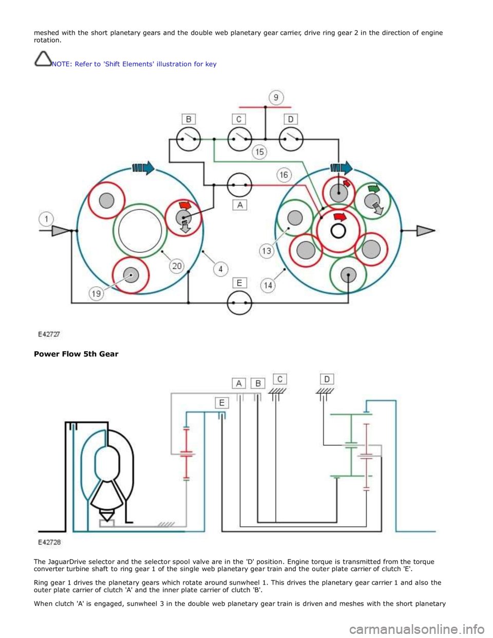
meshed with the short planetary gears and the double web planetary gear carrier, drive ring gear 2 in the direction of engine
rotation.
NOTE: Refer to 'Shift Elements' illustration for key
Power Flow 5th Gear
The JaguarDrive selector and the selector spool valve are in the 'D' position. Engine torque is transmitted from the torque
converter turbine shaft to ring gear 1 of the single web planetary gear train and the outer plate carrier of clutch 'E'.
Ring gear 1 drives the planetary gears which rotate around sunwheel 1. This drives the planetary gear carrier 1 and also the
outer plate carrier of clutch 'A' and the inner plate carrier of clutch 'B'.
When clutch 'A' is engaged, sunwheel 3 in the double web planetary gear train is driven and meshes with the short planetary
Page 1419 of 3039
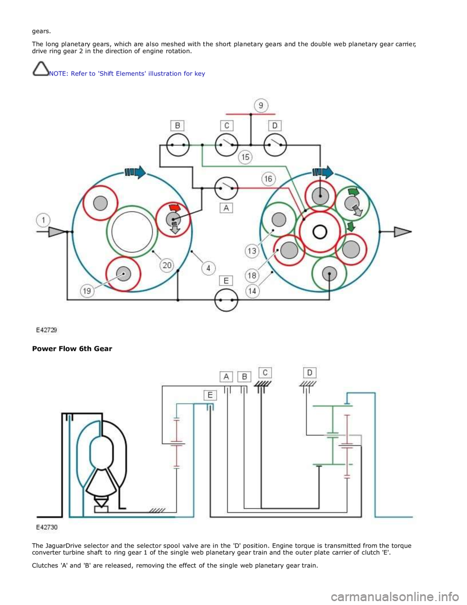
gears.
The long planetary gears, which are also meshed with the short planetary gears and the double web planetary gear carrier,
drive ring gear 2 in the direction of engine rotation.
NOTE: Refer to 'Shift Elements' illustration for key
Power Flow 6th Gear
The JaguarDrive selector and the selector spool valve are in the 'D' position. Engine torque is transmitted from the torque
converter turbine shaft to ring gear 1 of the single web planetary gear train and the outer plate carrier of clutch 'E'.
Clutches 'A' and 'B' are released, removing the effect of the single web planetary gear train.
Page 1420 of 3039
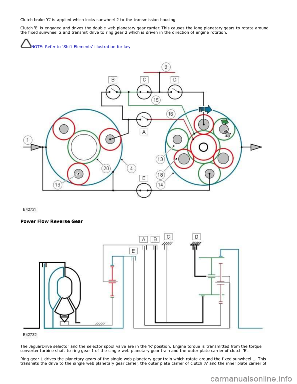
Clutch brake 'C' is applied which locks sunwheel 2 to the transmission housing.
Clutch 'E' is engaged and drives the double web planetary gear carrier. This causes the long planetary gears to rotate around
the fixed sunwheel 2 and transmit drive to ring gear 2 which is driven in the direction of engine rotation.
NOTE: Refer to 'Shift Elements' illustration for key
Power Flow Reverse Gear
The JaguarDrive selector and the selector spool valve are in the 'R' position. Engine torque is transmitted from the torque
converter turbine shaft to ring gear 1 of the single web planetary gear train and the outer plate carrier of clutch 'E'.
Ring gear 1 drives the planetary gears of the single web planetary gear train which rotate around the fixed sunwheel 1. This
transmits the drive to the single web planetary gear carrier, the outer plate carrier of clutch 'A' and the inner plate carrier of
Page 1421 of 3039
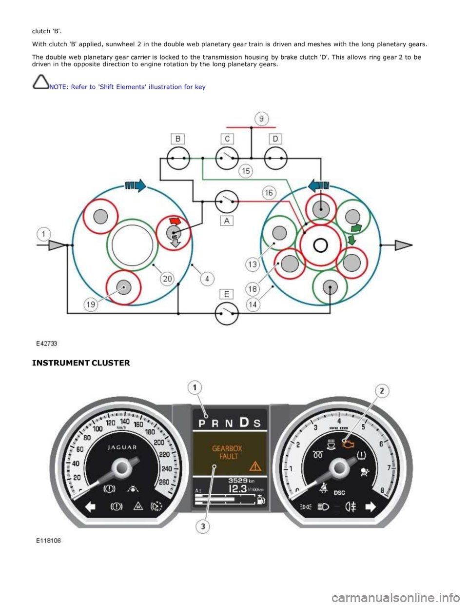
clutch 'B'.
With clutch 'B' applied, sunwheel 2 in the double web planetary gear train is driven and meshes with the long planetary gears.
The double web planetary gear carrier is locked to the transmission housing by brake clutch 'D'. This allows ring gear 2 to be
driven in the opposite direction to engine rotation by the long planetary gears.
NOTE: Refer to 'Shift Elements' illustration for key
INSTRUMENT CLUSTER
Page 1793 of 3039

. M–2
Benchmark noise against non-complaint
vehicle. . Trip (fuel) computer N–1
Check for consistent display (during test
drive) of valid 'Rolling Odometer' count in
Self-Diagnostic Mode/ETM test 24. Displays ---- , INV or 255 if message is not
received, or if received data is invalid. . N–2
Check that installed wheels and tires are
standard Jaguar fit. Confirm fitted wheel
size in IDS, 'ADD REMOVE ACCESSORY'
section. Non standard wheels and tires or incorrectly set
wheel size may lead to Odometer increment
inaccuracies. This will impact the distance
accumulators, which in turn affects the rolling
average, fuel economy and range values. Trip
distance accumulation will also be incorrect. . N–3
Consider noting odometer value and
resetting fuel computer system. Advise
customer to conduct brim-to-brim fuel
tank test. Use collected information to
determine if system accurate. . Column adjust O-1
Check with IDS for DTCs related to powered column system. . O-2
Check cluster battery supply voltage and
ground resistance. Check for loose
connections. . O-3
Check power column motors supply voltage. . O-4
Check power column switch for physical damage. . Passive Anti-Theft
System (PATS)
indicator P–1
Check for three second prove out when
vehicle start button is pressed. . . P–2
Check for loose connections/wiring continuity. . . P–3 Check ignition switch for physical damage. . Cluster illumination Q–1
Check for loose connections/wiring continuity. . . Q–2 Check dimmer switch operation. . Cluster backlight operation R–1
Is the backlight on other components inoperative. . . R–2 Check dimmer switch operation. . . R–3
Check for loose connections/wiring continuity. . Chime/tone operation S–1 Check vehicle configuration. . . S–2
Utilize lights ON, ignition OFF, door open warning to verify chime operation. . . S–3 Check appropriate sensing circuit. . Continuous chime/tone T–1 Check appropriate sensing circuit. . Unexpected chime operation U–1 Check vehicle configuration. . Message centre display illumination V–1
Is the backlight 'ON' and other components dim? . . V–2
Does the lighting level of other
components change when dimmer adjusted? . Message centre
display issue W–1
Perform Self-Diagnostic Mode test/ETM
tests 5 to 9, to prove out LCD display
function. . Message centre
missing lines X–1
Perform Self-Diagnostic Mode test/ETM
tests 5 to 9, to prove out LCD display
function. . Message centre
incorrect message Y–1 What is the message? . . Y–2
Check for open circuit/shorts in wiring to
related warning light trigger (module,
sensor, switch). . Cluster/connectivity Z–1 Check cluster battery and ignition wiring. . . Z–2 Check cluster grounds. . . Z–3 Disconnect/reconnect cluster. . . Z–4
Attempt to enter Self-Diagnostic
Mode/ETM to prove cluster response to inputs. . No crank AA–1
Check with IDS for presence of related
DTCs. . . AA–2
Is there a Passive Anti-Theft System (PATS) flash code? . . AA–3
Does the vehicle crank with the other passive key? .
Page 1794 of 3039
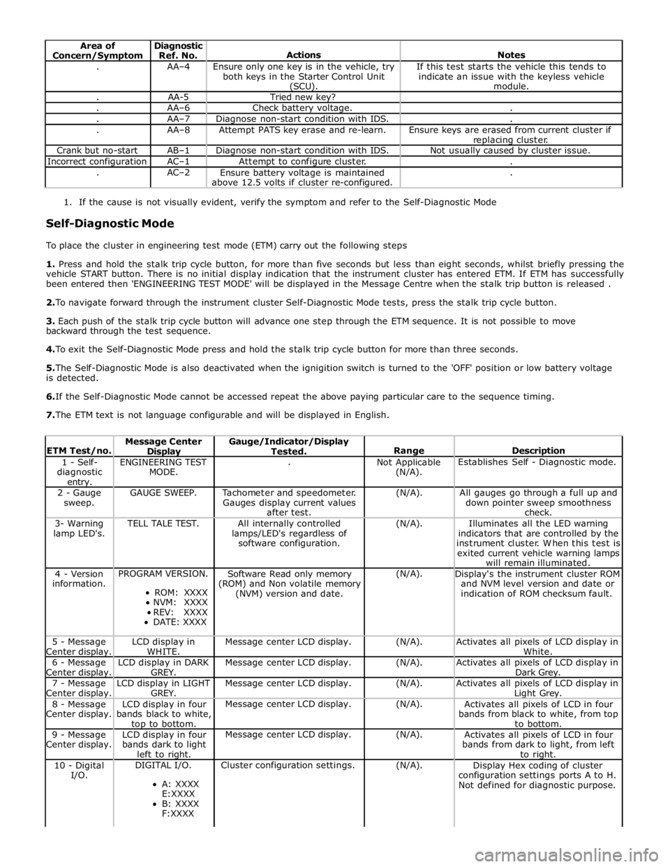
Area of
Concern/Symptom Diagnostic
Ref. No.
Actions
Notes . AA–4
Ensure only one key is in the vehicle, try
both keys in the Starter Control Unit (SCU). If this test starts the vehicle this tends to
indicate an issue with the keyless vehicle
module. . AA-5 Tried new key? . AA–6 Check battery voltage. . . AA–7 Diagnose non-start condition with IDS. . . AA–8 Attempt PATS key erase and re-learn.
Ensure keys are erased from current cluster if
replacing cluster. Crank but no-start AB–1 Diagnose non-start condition with IDS. Not usually caused by cluster issue. Incorrect configuration AC–1 Attempt to configure cluster. . . AC–2
Ensure battery voltage is maintained
above 12.5 volts if cluster re-configured. .
1. If the cause is not visually evident, verify the symptom and refer to the Self-Diagnostic Mode
Self-Diagnostic Mode
To place the cluster in engineering test mode (ETM) carry out the following steps
1. Press and hold the stalk trip cycle button, for more than five seconds but less than eight seconds, whilst briefly pressing the
vehicle START button. There is no initial display indication that the instrument cluster has entered ETM. If ETM has successfully
been entered then 'ENGINEERING TEST MODE' will be displayed in the Message Centre when the stalk trip button is released .
2. To navigate forward through the instrument cluster Self-Diagnostic Mode tests, press the stalk trip cycle button.
3. Each push of the stalk trip cycle button will advance one step through the ETM sequence. It is not possible to move
backward through the test sequence.
4. To exit the Self-Diagnostic Mode press and hold the stalk trip cycle button for more than three seconds.
5. The Self-Diagnostic Mode is also deactivated when the ignigition switch is turned to the 'OFF' position or low battery voltage
is detected.
6. If the Self-Diagnostic Mode cannot be accessed repeat the above paying particular care to the sequence timing.
7. The ETM text is not language configurable and will be displayed in English.
ETM Test/no. Message Center Display Gauge/Indicator/Display
Tested.
Range
Description 1 - Self-
diagnostic entry. ENGINEERING TEST
MODE. .
Not Applicable
(N/A). Establishes Self - Diagnostic mode. 2 - Gauge
sweep. GAUGE SWEEP.
Tachometer and speedometer.
Gauges display current values
after test. (N/A).
All gauges go through a full up and
down pointer sweep smoothness
check. 3- Warning
lamp LED's. TELL TALE TEST.
All internally controlled
lamps/LED's regardless of
software configuration. (N/A).
Illuminates all the LED warning
indicators that are controlled by the
instrument cluster. When this test is
exited current vehicle warning lamps
will remain illuminated. 4 - Version
information. PROGRAM VERSION.
ROM: XXXX
NVM: XXXX
REV: XXXX
DATE: XXXX Software Read only memory
(ROM) and Non volatile memory
(NVM) version and date. (N/A).
Display's the instrument cluster ROM
and NVM level version and date or
indication of ROM checksum fault. 5 - Message
Center display. LCD display in
WHITE. Message center LCD display. (N/A).
Activates all pixels of LCD display in
White. 6 - Message
Center display. LCD display in DARK
GREY. Message center LCD display. (N/A).
Activates all pixels of LCD display in
Dark Grey. 7 - Message
Center display. LCD display in LIGHT
GREY. Message center LCD display. (N/A).
Activates all pixels of LCD display in Light Grey. 8 - Message
Center display. LCD display in four
bands black to white, top to bottom. Message center LCD display. (N/A).
Activates all pixels of LCD in four
bands from black to white, from top
to bottom. 9 - Message
Center display. LCD display in four
bands dark to light
left to right. Message center LCD display. (N/A).
Activates all pixels of LCD in four
bands from dark to light, from left
to right. 10 - Digital
I/O. DIGITAL I/O.
A: XXXX
E:XXXX
B: XXXX
F:XXXX Cluster configuration settings. (N/A).
Display Hex coding of cluster
configuration settings ports A to H.
Not defined for diagnostic purpose.
Page 1797 of 3039
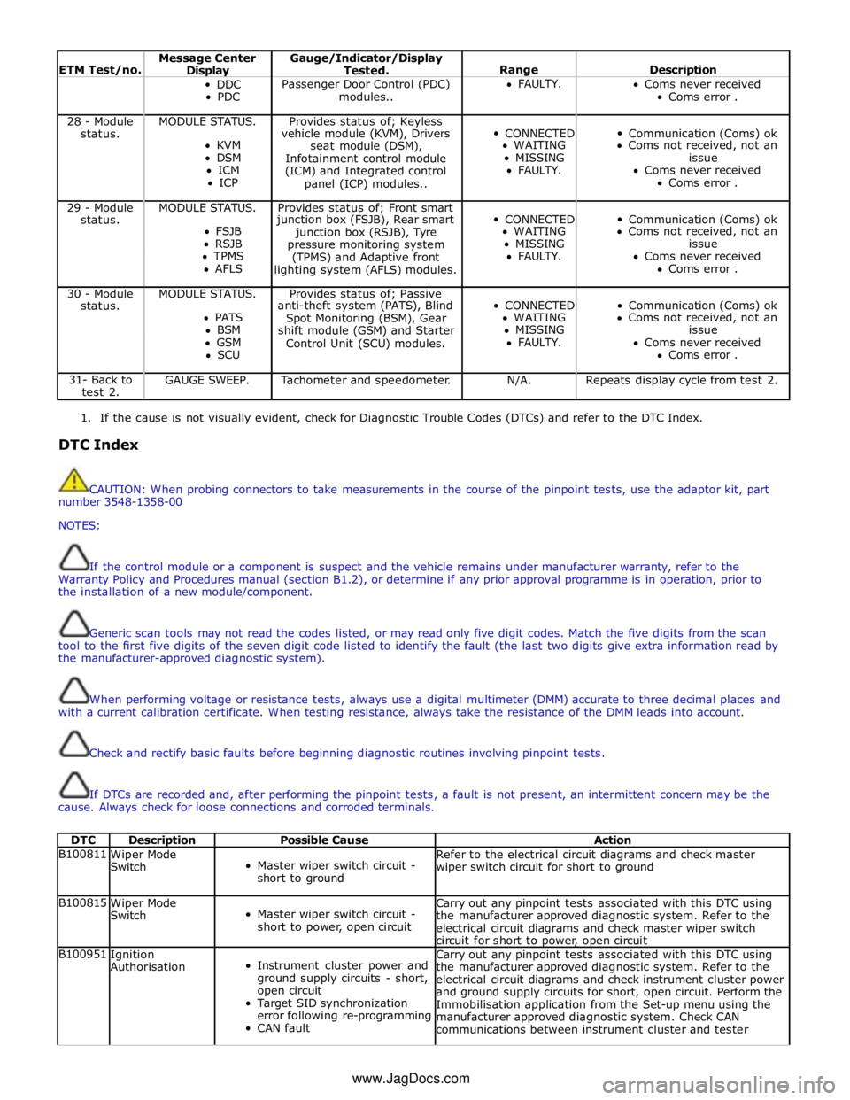
ETM Test/no. Message Center Display Gauge/Indicator/Display
Tested.
Range
Description DDC
PDC Passenger Door Control (PDC)
modules.. FAULTY.
Coms never received
Coms error . 28 - Module MODULE STATUS. Provides status of; Keyless
CONNECTED
Communication (Coms) ok status. vehicle module (KVM), Drivers KVM
seat module (DSM), WAITING Coms not received, not an DSM
Infotainment control module MISSING issue ICM
(ICM) and Integrated control FAULTY. Coms never received ICP
panel (ICP) modules.. Coms error . 29 - Module MODULE STATUS. Provides status of; Front smart
CONNECTED
Communication (Coms) ok status. junction box (FSJB), Rear smart FSJB
junction box (RSJB), Tyre WAITING Coms not received, not an RSJB
pressure monitoring system MISSING issue TPMS
(TPMS) and Adaptive front FAULTY. Coms never received AFLS
lighting system (AFLS) modules. Coms error . 30 - Module MODULE STATUS. Provides status of; Passive
CONNECTED
Communication (Coms) ok status. anti-theft system (PATS), Blind PATS
Spot Monitoring (BSM), Gear WAITING Coms not received, not an BSM
shift module (GSM) and Starter MISSING issue GSM
Control Unit (SCU) modules. FAULTY. Coms never received SCU Coms error . 31- Back to
test 2. GAUGE SWEEP. Tachometer and speedometer. N/A. Repeats display cycle from test 2.
1. If the cause is not visually evident, check for Diagnostic Trouble Codes (DTCs) and refer to the DTC Index.
DTC Index
CAUTION: When probing connectors to take measurements in the course of the pinpoint tests, use the adaptor kit, part
number 3548-1358-00
NOTES:
If the control module or a component is suspect and the vehicle remains under manufacturer warranty, refer to the
Warranty Policy and Procedures manual (section B1.2), or determine if any prior approval programme is in operation, prior to
the installation of a new module/component.
Generic scan tools may not read the codes listed, or may read only five digit codes. Match the five digits from the scan
tool to the first five digits of the seven digit code listed to identify the fault (the last two digits give extra information read by
the manufacturer-approved diagnostic system).
When performing voltage or resistance tests, always use a digital multimeter (DMM) accurate to three decimal places and
with a current calibration certificate. When testing resistance, always take the resistance of the DMM leads into account.
Check and rectify basic faults before beginning diagnostic routines involving pinpoint tests.
If DTCs are recorded and, after performing the pinpoint tests, a fault is not present, an intermittent concern may be the
cause. Always check for loose connections and corroded terminals.
DTC Description Possible Cause Action B100811
Wiper Mode
Switch
Master wiper switch circuit -
short to ground Refer to the electrical circuit diagrams and check master
wiper switch circuit for short to ground B100815
Wiper Mode
Switch
Master wiper switch circuit -
short to power, open circuit Carry out any pinpoint tests associated with this DTC using
the manufacturer approved diagnostic system. Refer to the
electrical circuit diagrams and check master wiper switch
circuit for short to power, open circuit B100951
Ignition
Authorisation
Instrument cluster power and
ground supply circuits - short,
open circuit
Target SID synchronization
error following re-programming
CAN fault Carry out any pinpoint tests associated with this DTC using
the manufacturer approved diagnostic system. Refer to the
electrical circuit diagrams and check instrument cluster power
and ground supply circuits for short, open circuit. Perform the
Immobilisation application from the Set-up menu using the
manufacturer approved diagnostic system. Check CAN
communications between instrument cluster and tester www.JagDocs.com
Page 1799 of 3039

DTC Description Possible Cause Action B100C67
Column Lock
Supply
Authorisation
Instrument cluster power and
ground supply circuits - short,
open circuit
LS CAN fault
CJB power and ground supply
circuits - short, open circuit
Vehicle speed present when
attempting to power ESCL
Engine speed present when
attempting to power ESCL
PowerMode status > 4 when
attempting to perform lock
action Carry out any pinpoint tests associated with this DTC using
the manufacturer approved diagnostic system. Refer to the
electrical circuit diagrams and check CJB power and ground
supply circuits for short, open circuit and instrument cluster
power and ground supply circuits for short, open circuit.
Check CAN communications between CJB and instrument
cluster. Check for invalid vehicle speed signal from
ABS/instrument cluster gateway. Check for invalid engine
speed signal from ECM/instrument cluster gateway. Check for
invalid signal from CJB B100C87
Column Lock
Supply
Authorisation
Instrument cluster power and
ground supply circuits - short,
open circuit
LS CAN fault
CJB power and ground supply
circuits - short, open circuit Carry out any pinpoint tests associated with this DTC using
the manufacturer approved diagnostic system. Refer to the
electrical circuit diagrams and check CJB power and ground
supply circuits for short, open circuit and instrument cluster
power and ground supply circuits for short, open circuit.
Check CAN communications between CJB and instrument
cluster B100D62
Column Lock
Authorisation
CAN fault
ESCL power and ground supply
circuits - short, open circuit
Instrument cluster power and
ground supply circuits - short,
open circuit
Incorrect ESCL or instrument
cluster installed
Target SID synchronization
error following re-programming
Noise/EMC related error Carry out any pinpoint tests associated with this DTC using
the manufacturer approved diagnostic system. Check CAN
communication between Electronic Steering Column Lock and
instrument cluster. Refer to the electrical circuit diagrams
and check Electronic Steering Column Lock power and ground
supply circuits for short, open circuit and Instrument cluster
power and ground supply circuits for short, open circuit.
Check correct Electronic Steering Column Lock and instrument
cluster installed. Perform the Immobilisation application from
the Set-up menu using the manufacturer approved diagnostic
system. Check CAN network for interference/EMC related
issues B100D64
Column Lock
Authorisation
Algorithm based failure-signal
plausibility failure
CAN fault
ESCL power and ground supply
circuits - short, open circuit
Instrument cluster power and
ground supply circuits - short,
open circuit If the customer has not reported a non start issue, clear the
DTC and check vehicle starts correctly. If a non start issue
has been reported run the manufacturers approved
diagnostic system Start Authorisation Application and follow
the actions required for this DTC. Carry out any pinpoint
tests associated with this DTC using the manufacturer
approved diagnostic system. Check CAN communication
between Electronic Steering Column Lock and instrument
cluster (check transmission out speed, vehicle speed, engine
speed, gear position and powermode signals to Electronic
Steering Column Lock). Refer to the electrical circuit
diagrams and check Electronic Steering Column Lock power
and ground supply circuits for short, open circuit and
Instrument cluster power and ground supply circuits for
short, open circuit. B100D87
Column Lock
Authorisation -
Missing message
Missing message
CAN fault
No response from electric
steering column lock control
module, instrument cluster,
central junction box Battery
voltage at electric
steering column lock control
module too low
Electric steering column lock
control module, instrument
cluster, central junction box
fault
Clear DTC, repeatedly lock and unlock car using the
key fob and retest. Check for related DTCs and refer
to the relevant DTC index
If the fault is cleared, notify the customer that the
steering column lock may fail to unlock if the vehicle
is parked with a high steering angle or with the road
wheel against a curb. If the column lock is failing to
disengage, the customer may be able to rectify this
by rotating the steering wheel while pressing the
engine start button
If fault persists, complete a CAN network integrity
test using the manufacturers approved diagnostic
system. Alternatively, refer to the electrical circuit
diagrams and check CAN circuits between the central
junction box, the instrument cluster and the
electronic steering column lock. Refer to the electrical
circuit diagrams and check the central junction box,
the instrument cluster and the electronic steering
column lock power and ground supply circuits for short
circuit to ground, short circuit to power, open circuit,
high resistance. Repair circuit(s) as required. Clear
DTC, perform an on demand self-test and retest
If fault persists, check that the vehicle battery supply
voltage is between 9-16 volts. Rectify as required
Page 1800 of 3039

DTC Description Possible Cause Action B100D96
Column Lock
Authorisation -
Component
internal failure
Battery voltage at electric
steering column lock control
module too low
Torque load on steering
column
CAN fault
Electric steering column lock
control module - Internal
failure
Clear DTC, repeatedly lock and unlock car using the
key fob and retest
If fault persists, check that the vehicle battery supply
voltage is between 9-16 volts. Rectify as required
Ensure the column lock bolt movement is not
obstructed or restricted (the parked position of the
road wheels may be exerting a turning force through
the steering column, preventing the lock from
releasing. The steering wheel may need to be held
against the force to allow the column lock to
release). Clear DTC, repeatedly lock and unlock car
using the key fob and retest
If fault persists, complete a CAN network integrity
test using the manufacturers approved diagnostic
system. Alternatively, refer to the electrical circuit
diagrams and check CAN circuits between the central
junction box, the instrument cluster and the
electronic steering column lock. Refer to the electrical
circuit diagrams and check the central junction box,
the instrument cluster and the electronic steering
column lock power and ground supply circuits for short
circuit to ground, short circuit to power, open circuit,
high resistance. Repair circuit(s) as required. Clear
DTC, perform an on demand self-test and retest
If fault persists, check and install a new electric
steering column lock control module as required B102487 Start Control Unit
Smart card docking station
failure - slave node not
responding Carry out any pinpoint tests associated with this DTC using
the manufacturer approved diagnostic system. Refer to the
electrical circuit diagrams and check the smart card docking
station LIN circuit for short, open circuit. Suspect the smart
card docking station, check and install a new docking station
as required, refer to the new module/component installation
note at the top of the DTC Index B104611
Front Fog Lamp
Control Switch
Fog lamp switch circuit - short
to ground Refer to the electrical circuit diagrams and check fog lamp
switch circuit for short to ground B104615
Front Fog Lamp
Control Switch
Fog lamp switch circuit - short
to power, open circuit Refer to the electrical circuit diagrams and check fog lamp
switch circuit for short to power, open circuit B104811
Brake Fluid Level
Switch
Brake fluid level switch circuit
- short to ground Refer to the electrical circuit diagrams and check brake fluid
level switch circuit for short to ground B10A011
Wiper/ Washer
Switch
Wash/wipe circuit - short to
ground Refer to the electrical circuit diagrams and check wash/wipe
circuit for short to ground B10A015
Wiper/ Washer
Switch
Wash/wipe circuit - short to
power, open circuit Carry out any pinpoint tests associated with this DTC using
the manufacturer approved diagnostic system. Refer to the
electrical circuit diagrams and check wash/wipe circuit for
short to power, open circuit B10A611 Main Light Switch
Master lighting switch circuit -
short to ground Refer to the electrical circuit diagrams and check master
lighting switch circuit for short to ground B10A615 Main Light Switch
Master lighting switch circuit -
short to power, open circuit Carry out any pinpoint tests associated with this DTC using
the manufacturer approved diagnostic system. Refer to the
electrical circuit diagrams and check master lighting switch
circuit for short to power, open circuit B112B87
Steering Wheel
Module
Steering wheel module failure
- slave node not responding Carry out any pinpoint tests associated with this DTC using
the manufacturer approved diagnostic system. Refer to the
electrical circuit diagrams and check the clockspring LIN
circuit for short, open circuit. Suspect the clockspring, check
and install a new clockspring as required, refer to the new
module/component installation note at the top of the DTC
Index B115C7A
Transfer Fuel
Pump
Fuel pump system fault Check for fuel system jet pump or jet pump fuel level sensor
fault B1A8515
Ambient Light
Sensor
Autolamp sensor circuit - short
to power, open circuit Carry out any pinpoint tests associated with this DTC using
the manufacturer approved diagnostic system. Refer to the
electrical circuit diagrams and check autolamp sensor circuit
for short to power, open circuit
Page 1801 of 3039

DTC Description Possible Cause Action B1B0100 Key Transponder
Operator only cycles one key
During transponder key
programming the instrument
cluster, smartcard docking
station or key loses
power/circuit failure
Faulty key during key
programming
Unable to program
transponder key due to
noise/EMC related error Ensure all keys to be programmed are available. Refer to
electrical circuit diagrams and check power and ground
supply circuits to all relevant modules. Replace faulty key
and repeat key programming. Check CAN network for
interference/EMC related issues B1B0105 Key Transponder
Error following SCU
replacement
Smartcard docking station
power and ground supply
circuits - short, open circuit
LIN fault
Instrument cluster power and
ground supply circuits - short,
open circuit Carry out any pinpoint tests associated with this DTC using
the manufacturer approved diagnostic system. Perform the
Immobilisation application from the Set-up menu using the
manufacturer approved diagnostic system. Refer to the
electrical circuit diagrams and check smartcard docking
station power and ground supply circuits for short, open
circuit and instrument cluster power and ground supply
circuits for short, open circuit. Check LIN communications
between smartcard docking station and instrument cluster B1B0151 Key Transponder
LIN fault
Instrument cluster power and
ground supply circuits - short,
open circuit
Key fault
Smartcard docking station
power and ground supply
circuits - short, open circuit
Attempted to program a non
default key Carry out any pinpoint tests associated with this DTC using
the manufacturer approved diagnostic system. Check LIN
communications between smartcard docking station and
instrument cluster. Refer to the electrical circuit diagrams
and check smartcard docking station power and ground
supply circuits for short, open circuit and instrument cluster
power and ground supply circuits for short, open circuit.
Confirm transponder key operation. Ensure new keys are from
a known source B1B0155 Key Transponder
Un-programmed key inserted
in SCU2
A non default key inserted
during key programming Confirm the correct keys are used B1B0162 Key Transponder
Instrument cluster power and
ground supply circuits - short,
open circuit
Smartcard docking station
power and ground supply
circuits - short, open circuit
Incorrect instrument cluster or
smartcard docking station
installed
Error during or following the
Write Target SID routine
Noise/EMC related error Carry out any pinpoint tests associated with this DTC using
the manufacturer approved diagnostic system. Refer to the
electrical circuit diagrams and check smartcard docking
station power and ground supply circuits for short, open
circuit and instrument cluster power and ground supply
circuits for short, open circuit. Check correct instrument
cluster and smartcard docking station are installed. Perform
the Immobilisation application from the Set-Up menu using
the manufacturer approved diagnostic system. Check CAN
network for interference/EMC related issues B1B0164 Key Transponder
LIN fault
Instrument cluster power and
ground supply circuits - short,
open circuit
Transponder key fault
Smartcard docking station
power and ground supply
circuits - short, open circuit
Error occurred during
transponder key programming Carry out any pinpoint tests associated with this DTC using
the manufacturer approved diagnostic system. Check LIN
communications between smartcard docking station and
instrument cluster. Refer to the electrical circuit diagrams
and check smartcard docking station power and ground
supply circuits for short, open circuit and instrument cluster
power and ground supply circuits for short, open circuit.
Confirm transponder key operation. Repeat transponder key
programming B1B0167 Key Transponder
LIN fault
Instrument cluster power and
ground supply circuits - short,
open circuit
Transponder key fault
Smartcard docking station
power and ground supply
circuits - short, open circuit
Another key in close proximity
Instrument cluster in incorrect Carry out any pinpoint tests associated with this DTC using
the manufacturer approved diagnostic system. Check LIN
communications between smartcard docking station and
instrument cluster. Refer to the electrical circuit diagrams
and check smartcard docking station power and ground
supply circuits for short, open circuit and instrument cluster
power and ground supply circuits for short, open circuit.
Confirm transponder key operation. Confirm single key
operation. Ensure instrument cluster in correct mode i.e.
Auto Enable, Key erase etc. Ensure new keys are from a
known source. Check for intermittent power and ground to