Module JAGUAR XFR 2010 1.G Workshop Manual
[x] Cancel search | Manufacturer: JAGUAR, Model Year: 2010, Model line: XFR, Model: JAGUAR XFR 2010 1.GPages: 3039, PDF Size: 58.49 MB
Page 2692 of 3039

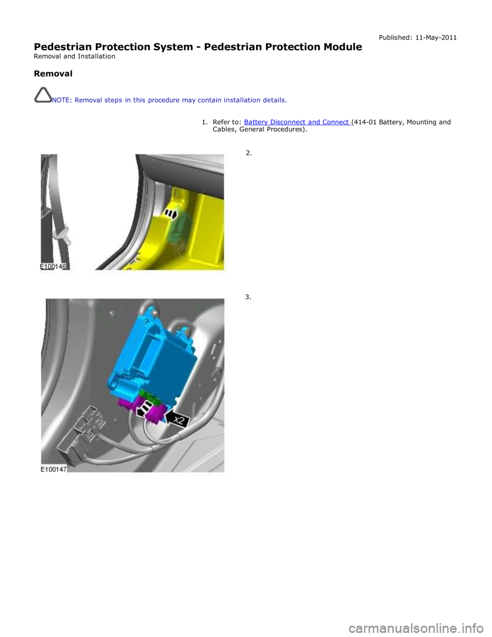
Pedestrian Protection System - Pedestrian Protection Module
Removal and Installation
Removal
NOTE: Removal steps in this procedure may contain installation details. Published: 11-May-2011
1. Refer to: Battery Disconnect and Connect (414-01 Battery, Mounting and Cables, General Procedures).
2.
3.
Page 2714 of 3039

- Disadvantage: Scarring and hardening of the surface.
Flattening using a copper electrode.
- Small, sharp dents that face outwards can be worked on with a copper electrode.
Flattening using a flame and body files.
NOTE: When applied correctly, this method can be used with all the attached parts still in place (roof headlining,
wiring harnesses etc.).
- Small, soft dents (only slight stretching): Working at the edges of the dent in an inward spiral pattern, the dent
is heated with an oxyacetylene torch (torch size 1 - 2 mm, excess gas flame) to approx. 250° C.
- Working rapidly with a body file extracts heat from the edge area until the dent is flattened. Preferably alternate
between two files. This increases the amount of heat that can be extracted.
Safety measures
The electronic control modules (ECM) fitted to vehicles make it advisable to follow suitable precautions prior to carrying
out welding repair operations. Harsh conditions of heat and vibration may be generated during these operations which
could cause damage to the modules. In particular, it is essential to follow the appropriate precautions when
disconnecting or removing the airbag RCM.
Do not allow electronic modules or lines to come into contact with the ground connection or the welding electrode.
Seat belt anchorages are a safety critical. When making repairs in these areas, it is essential to follow design
specifications. Note that extra strength low alloy steel may be used for seat belt anchorages. Where possible, the
original production assembly should be used, complete with its seat belt anchorages, or the cut line should be so
arranged that the original seat belt anchorage is not disturbed.
All welds within 250mm (9.842) of seat belt anchorages must be carefully checked for weld quality, including spacing of
spot welds.
Remove the battery before carrying out welding work in its vicinity.
Utmost care must be taken when welding near the fuel tank or other components that contain fuel. If the tank filler
neck or a fuel line must be detached to allow access for welding work, then the fuel tank must be drained and removed.
Never weld, on components of a filled air conditioning system. The same applies if there is a risk of the air conditioning
system heating up.
Connect the ground connection of the electrical welder directly to the part that is to be welded. Make sure that there
are no electrically insulating parts between the ground connection and the welding point.
Adjacent vehicle parts and adjacent vehicles must be shielded against flying sparks and heat.
Pedestrian protection system
The pedestrian protection system is designed to mitigate injuries in a pedestrian collision with the vehicle. It does this by
utilizing a pair of pyrotechnic actuators to lift the hood away from the engine, creating a cushioned impact between the
pedestrian and the vehicle. It is essential that any repair or replacement operations do not affect the safe working of the
system.
For additional information, refer to: Pedestrian Protection System (501-20C Pedestrian Protection System, Description and Operation).
Resistance spot welding
Where resistance spot welds have been used in production, they must be reproduced with new spot welds in replacement
where possible. All such reproduction spot welds should be spaced 25 to 30mm apart.
Setting up the equipment and co-ordinating the welding parameters.
Equipment:
- Follow the equipment manufacturer's instructions for the equipment settings.
- Select the correct electrode arms (as short as possible).
- Align the electrode arms and tips exactly.
- Electrode tips should be convex (rough shaping with a file, fine shaping with a sanding block).
Body:
- Make sure that the flanges to be joined lie perfectly flat to one another.
- Prepare a bare metal joint surface (inside and outside).
Notes on technique/method:
- Carry out a test weld on a sample piece of the material coated in welding paste.
- If any metal parts are located between the electrode arms then there will be a loss of induction and therefore
power (adjust current setting).
- The power needs to be adjusted for high-strength low alloy steel.
- Repeated welding on old welding points often leads to poor quality welds.
- Keep the electrode tips as near as possible to an angle of 90° to the contact surface.
- Keep the pressure on the electrodes for a short period after finishing the weld.
- The electrodes work best if their shape is convex. Clean the contact surface of the electrodes regularly.
Resistance spot welding panels where the total thickness is 3 mm or more
For all repairs to modern Jaguar vehicles, spot-welding equipment should be suitable for reliable welding of zinc-plated,
high-strength and high-tensile steels in three or more layers, up to 5 mm total thickness. If these requirements are not
fulfilled, plug welding must be used for safety reasons. The electrical specifications (current, resistance, heat) of the
spot-welding equipment have different validity, depending upon the type of equipment. Therefore, it is essential that the
manufacturer's instructions are observed with regard to the actual welding performance.
www.JagDocs.com
Page 2759 of 3039

Front End Sheet Metal Repairs - Fender Apron Panel
Removal and Installation
Removal Published: 11-May-2011
1. NOTE: The fender apron panel is manufactured from mild
steel.
The fender apron panel is serviced as a separate weld-on
panel.
2. The fender apron panel is replaced in conjunction with:
Front bumper cover
Front fender
Fender apron panel closing panel
Hood
Hood hinge
Hood strut mounting bracket
Fender mounting plate
3. For additional information relating to this repair procedure please see
the following:
For additional information, refer to: Health and Safety Precautions (100-00 General Information, Description and Operation) /
Body Repairs (501-25A Body Repairs - General Information, Description and Operation) /
Corrosion Protection (501-25B Body Repairs - Corrosion Protection, Description and Operation) /
Body and Frame (501-26 Body Repairs - Vehicle Specific Information and Tolerance Checks, Description and Operation).
4. Remove the hood.
For additional information, refer to: Hood (501-02 Front End Body Panels, Removal and Installation).
5. Remove the hood hinge.
6. Remove the fender apron panel closing panel.
For additional information, refer to: Fender Apron Panel Closing Panel (501-27 Front End Sheet Metal Repairs, Removal and Installation).
7. Disconnect the generator electrical connectors.
8. Remove the windshield wiper motor and linkage.
For additional information, refer to: Windshield Wiper Motor (501-16 Wipers and Washers, Removal and Installation).
9. Remove the ECM (engine control module).
For additional information, refer to: Engine Control Module (ECM)
(303-14A, Removal and Installation) /
Engine Control Module (ECM) (303-14B Electronic Engine Controls - V6 3.0L Petrol, Removal and Installation) /
Engine Control Module (ECM) (303-14C, Removal and Installation). www.JagDocs.com
Page 2829 of 3039

(414-01 Battery, Mounting and Cables, General Procedures).
6. Disconnect the generator electrical connectors.
7. Remove the windshield glass.
For additional information, refer to: Windshield Glass (501-11 Glass, Frames and Mechanisms, Removal and Installation).
8. Remove the rear window glass.
For additional information, refer to: Rear Window Glass (501-11 Glass, Frames and Mechanisms, Removal and Installation).
9. Remove the roof opening panel frame.
For additional information, refer to: Roof Opening Panel Frame (501-17 Roof Opening Panel, Removal and Installation).
10. Remove the driver and passenger side front scuff plate trim panels.
For additional information, refer to: Front Scuff Plate Trim Panel (501-05 Interior Trim and Ornamentation, Removal and Installation).
11. Remove the driver and passenger side rear scuff plate trim panels.
For additional information, refer to: Rear Scuff Plate Trim Panel (501-05 Interior Trim and Ornamentation, Removal and Installation).
12. Remove the driver and passenger side air curtain modules.
For additional information, refer to: Side Air Curtain Module (501-20B Supplemental Restraint System, Removal and Installation).
13. Remove the rear seat backrest.
14. Remove the driver and passenger side rear safety belt retractors.
For additional information, refer to: Rear Safety Belt Retractor (501-20A Safety Belt System, Removal and Installation).
15. Remove the rear center safety belt retractor.
For additional information, refer to: Rear Center Safety Belt Retractor (501-20A Safety Belt System, Removal and Installation).
16. Remove the driver and passenger side RF filters.
17. Remove the diversity antenna module.
18. Remove the antenna.
For additional information, refer to: Navigation System Antenna (419-07 Navigation System, Removal and Installation).
19. Release and position the roof wiring harnesses to one side
20. Position the roof opening panel front and rear drain hoses to one side.
21. Remove the driver and passenger side roof mouldings.
22. Drill out the spot welds.
www.JagDocs.com
Page 2836 of 3039

(414-01 Battery, Mounting and Cables, General Procedures).
6. Disconnect the generator electrical connectors.
7. Remove the windshield glass.
For additional information, refer to: Windshield Glass (501-11 Glass, Frames and Mechanisms, Removal and Installation).
8. Remove the rear window glass.
For additional information, refer to: Rear Window Glass (501-11 Glass, Frames and Mechanisms, Removal and Installation).
9. Remove the headliner.
For additional information, refer to: Headliner (501-05 Interior Trim and Ornamentation, Removal and Installation).
10. Remove the driver and passenger side front scuff plate trim panels.
For additional information, refer to: Front Scuff Plate Trim Panel (501-05 Interior Trim and Ornamentation, Removal and Installation).
11. Remove the driver and passenger side rear scuff plate trim panels.
For additional information, refer to: Rear Scuff Plate Trim Panel (501-05 Interior Trim and Ornamentation, Removal and Installation).
12. Remove the driver and passenger side air curtain modules.
For additional information, refer to: Side Air Curtain Module (501-20B Supplemental Restraint System, Removal and Installation).
13. Remove the rear seat backrest.
14. Remove the driver and passenger side rear safety belt retractors.
For additional information, refer to: Rear Safety Belt Retractor (501-20A Safety Belt System, Removal and Installation).
15. Remove the rear center safety belt retractor.
For additional information, refer to: Rear Center Safety Belt Retractor (501-20A Safety Belt System, Removal and Installation).
16. Remove the driver and passenger side RF filters.
17. Remove the diversity antenna module.
18. Remove the antenna.
For additional information, refer to: Navigation System Antenna (419-07 Navigation System, Removal and Installation).
19. Release and position the roof wiring harnesses to one side
20. Remove the driver and passenger side roof mouldings.
21. Drill out the spot welds.
Page 2857 of 3039

Panel Sheet Metal Repairs, Removal and Installation).
7. Remove the side air curtain module.
For additional information, refer to: Side Air Curtain Module (501-20B Supplemental Restraint System, Removal and Installation).
8. Remove the front seat.
For additional information, refer to: Front Seat (501-10 Seating, Removal and Installation).
9. Remove the floor covering.
10. If the passenger side A-pillar reinforcement is to be repaired, remove
the heater core and evaporator core housing.
For additional information, refer to: Heater Core and Evaporator Core Housing (412-01 Climate Control, Removal and Installation).
11. If the right-hand A-pillar reinforcement is to be repaired, remove the
central junction box.
For additional information, refer to: Central Junction Box (CJB) (418-00 Module Communications Network, Removal and Installation).
12. If the drivers side A-pillar reinforcement is to be repaired, remove the
pedal box.
13. Release and lay aside the insulating material at the inner bulkhead.
14. Release and position aside the inner bulkhead and floor panel wiring
harness.
15. NOTE: The NVH components may have already been
removed on the outer panel.
Remove the upper and lower NVH components and if
undamaged retain for reuse.
Page 2903 of 3039

and Installation).
5. Disconnect the generator electrical connectors.
6. Remove the right-hand and left-hand front scuff plate trim panels.
For additional information, refer to: Front Scuff Plate Trim Panel (501-05 Interior Trim and Ornamentation, Removal and Installation).
7. Remove the front and rear door weatherstrips.
8. Remove the right-hand and left-hand rear scuff plate trim panels.
For additional information, refer to: Rear Scuff Plate Trim Panel (501-05 Interior Trim and Ornamentation, Removal and Installation).
9. Remove the headliner.
For additional information, refer to: Headliner (501-05 Interior Trim and Ornamentation, Removal and Installation).
10. Remove the side air curtain module.
For additional information, refer to: Side Air Curtain Module (501-20B Supplemental Restraint System, Removal and Installation).
11. Remove the rear seat cushion.
For additional information, refer to: Rear Seat Cushion (501-10 Seating, Removal and Installation).
12. Remove the rear seat backrest.
13. Release and position the roof wiring harness to one side.
14. Remove the roof moulding.
15. Remove the cowl side trim panel.
For additional information, refer to: Cowl Side Trim Panel (501-05 Interior Trim and Ornamentation, Removal and Installation).
16. Remove the front safety belt retractor.
For additional information, refer to: Front Safety Belt Retractor (501-20A Safety Belt System, Removal and Installation).
17. Remove the B-pillar side impact sensor.
For additional information, refer to: B-Pillar Side Impact Sensor (501-20B Supplemental Restraint System, Removal and Installation).
18. Remove the C-pillar side impact sensor.
For additional information, refer to: C-Pillar Side Impact Sensor (501-20B Supplemental Restraint System, Removal and Installation).
19. Release and position the floor covering to one side.
20. Release and position the inner rocker panel wiring harness to one side.
21. Remove the rear wheel and tire.
For additional information, refer to: Wheel and Tire (204-04 Wheels and
Page 2943 of 3039

Rear End Sheet Metal Repairs - Back Panel
Removal and Installation
Removal Published: 11-May-2011
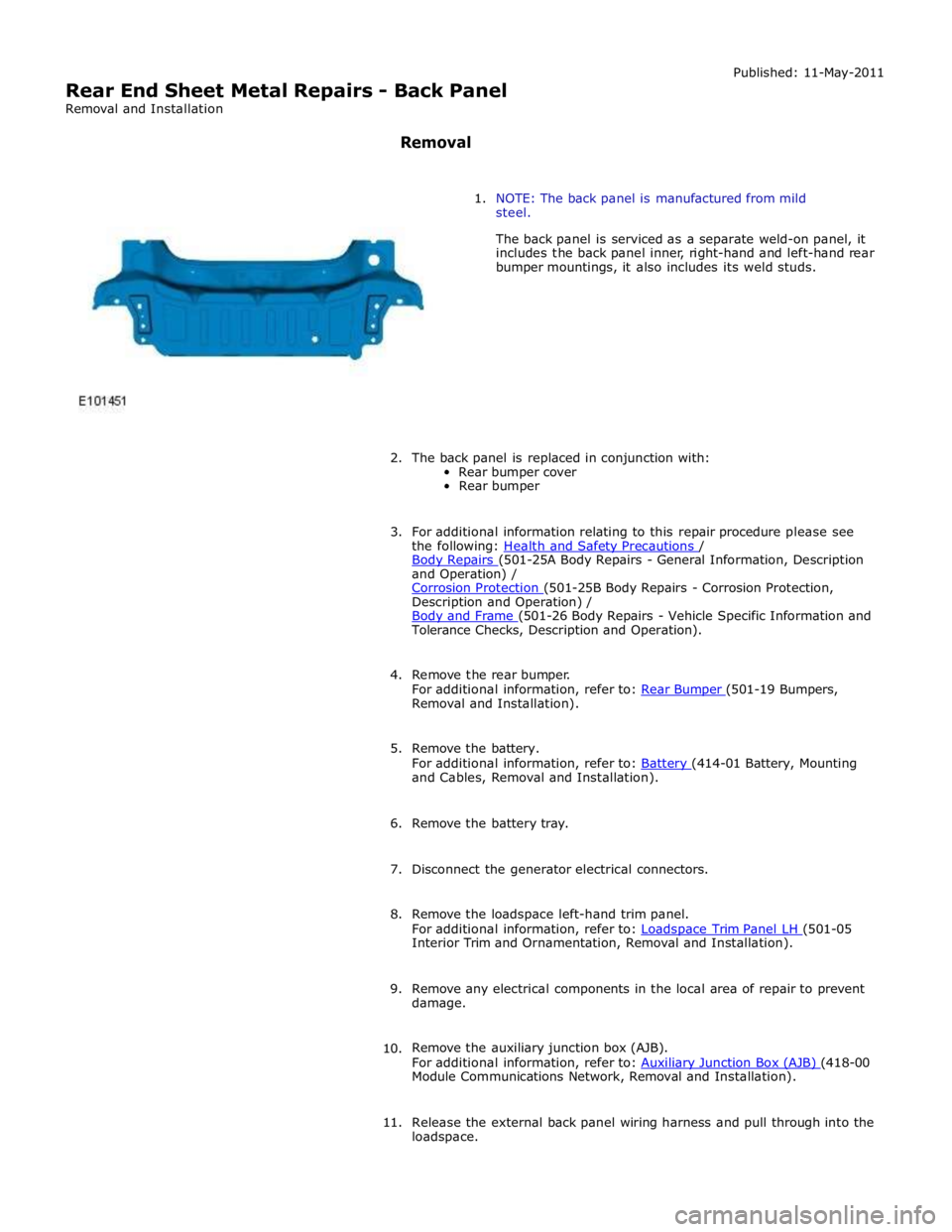
1. NOTE: The back panel is manufactured from mild
steel.
The back panel is serviced as a separate weld-on panel, it
includes the back panel inner, right-hand and left-hand rear
bumper mountings, it also includes its weld studs.
2. The back panel is replaced in conjunction with:
Rear bumper cover
Rear bumper
3. For additional information relating to this repair procedure please see
the following: Health and Safety Precautions / Body Repairs (501-25A Body Repairs - General Information, Description and Operation) /
Corrosion Protection (501-25B Body Repairs - Corrosion Protection, Description and Operation) /
Body and Frame (501-26 Body Repairs - Vehicle Specific Information and Tolerance Checks, Description and Operation).
4. Remove the rear bumper.
For additional information, refer to: Rear Bumper (501-19 Bumpers, Removal and Installation).
5. Remove the battery.
For additional information, refer to: Battery (414-01 Battery, Mounting and Cables, Removal and Installation).
6. Remove the battery tray.
7. Disconnect the generator electrical connectors.
8. Remove the loadspace left-hand trim panel.
For additional information, refer to: Loadspace Trim Panel LH (501-05 Interior Trim and Ornamentation, Removal and Installation).
9. Remove any electrical components in the local area of repair to prevent
damage.
10. Remove the auxiliary junction box (AJB).
For additional information, refer to: Auxiliary Junction Box (AJB) (418-00 Module Communications Network, Removal and Installation).
11. Release the external back panel wiring harness and pull through into the
loadspace.
Page 2949 of 3039

Removal and Installation).
7. Remove the battery.
For additional information, refer to: Battery (414-01 Battery, Mounting and Cables, Removal and Installation).
8. Disconnect the generator electrical connectors.
9. If the left-hand rear quarter panel is to be repaired, remove the
loadspace left-hand trim panel.
For additional information, refer to: Loadspace Trim Panel LH (501-05 Interior Trim and Ornamentation, Removal and Installation).
10. If the right-hand rear quarter panel is to be repaired, remove the
auxiliary junction box (AJB).
For additional information, refer to: Auxiliary Junction Box (AJB) (418-00 Module Communications Network, Removal and Installation).
11. Remove any electrical components in the local area of repair to prevent
damage.
12. Remove the rear muffler.
For additional information, refer to: Rear Muffler (309-00C Exhaust System - V8 5.0L Petrol/V8 S/C 5.0L Petrol, Removal and Installation) /
Rear Muffler (309-00C Exhaust System - V8 5.0L Petrol/V8 S/C 5.0L Petrol, Removal and Installation) /
Rear Muffler (309-00C Exhaust System - V8 5.0L Petrol/V8 S/C 5.0L Petrol, Removal and Installation).
13. Remove the exhaust muffler and tailpipe heatshield.
14. Remove the rear scuff plate trim panel.
For additional information, refer to: Rear Scuff Plate Trim Panel (501-05 Interior Trim and Ornamentation, Removal and Installation).
15. Remove the loadspace trim panel.
For additional information, refer to: Loadspace Trim Panel (501-05 Interior Trim and Ornamentation, Removal and Installation).
16. Remove the forced air extraction grille.
17. Release and lay aside the back panel and loadspace wiring harness.
18. Remove the luggage compartment lid weatherstrip.
19. Remove the rear bumper cover side retainer.
20. Remove the roof moulding.
21. Remove the headliner.
For additional information, refer to: Headliner (501-05 Interior Trim and Ornamentation, Removal and Installation).
22. Remove the side air curtain module.
www.JagDocs.com
Page 2950 of 3039

Supplemental Restraint System, Removal and Installation).
23. Remove the rear window glass.
24. Remove the audio unit antenna amplifier.
For additional information, refer to: Audio Unit Antenna Amplifier (415-01A Information and Entertainment System, Removal and
Installation).
25. If the left-hand rear quarter panel is to be repaired, remove the diversity
antenna module.
26. Remove the C-Pillar side impact sensor.
For additional information, refer to: C-Pillar Side Impact Sensor (501-20B Supplemental Restraint System, Removal and Installation).
27. Remove the rear door striker.
28. Remove the luggage compartment lid.
29. If the right-hand rear quarter panel is to be repaired, drain the fuel tank.
For additional information, refer to: Fuel Tank Draining (310-00 Fuel System - General Information, General Procedures).
30. If the right-hand rear quarter panel is to be repaired, remove the fuel
filler door.
31. If the right-hand rear quarter panel is to be repaired, remove the fuel
tank filler pipe.
For additional information, refer to: Fuel Tank Filler Pipe (310-01 Fuel
Tank and Lines - 3.0L, Removal and Installation) /
Fuel Tank Filler Pipe (310-01 Fuel Tank and Lines - 4.2L, Removal and
Installation).
32. Remove the luggage compartment lid hinge.