JAGUAR XJ6 1994 2.G Workshop Manual
Manufacturer: JAGUAR, Model Year: 1994, Model line: XJ6, Model: JAGUAR XJ6 1994 2.GPages: 521, PDF Size: 17.35 MB
Page 111 of 521
b Exhaust System (V12)
8
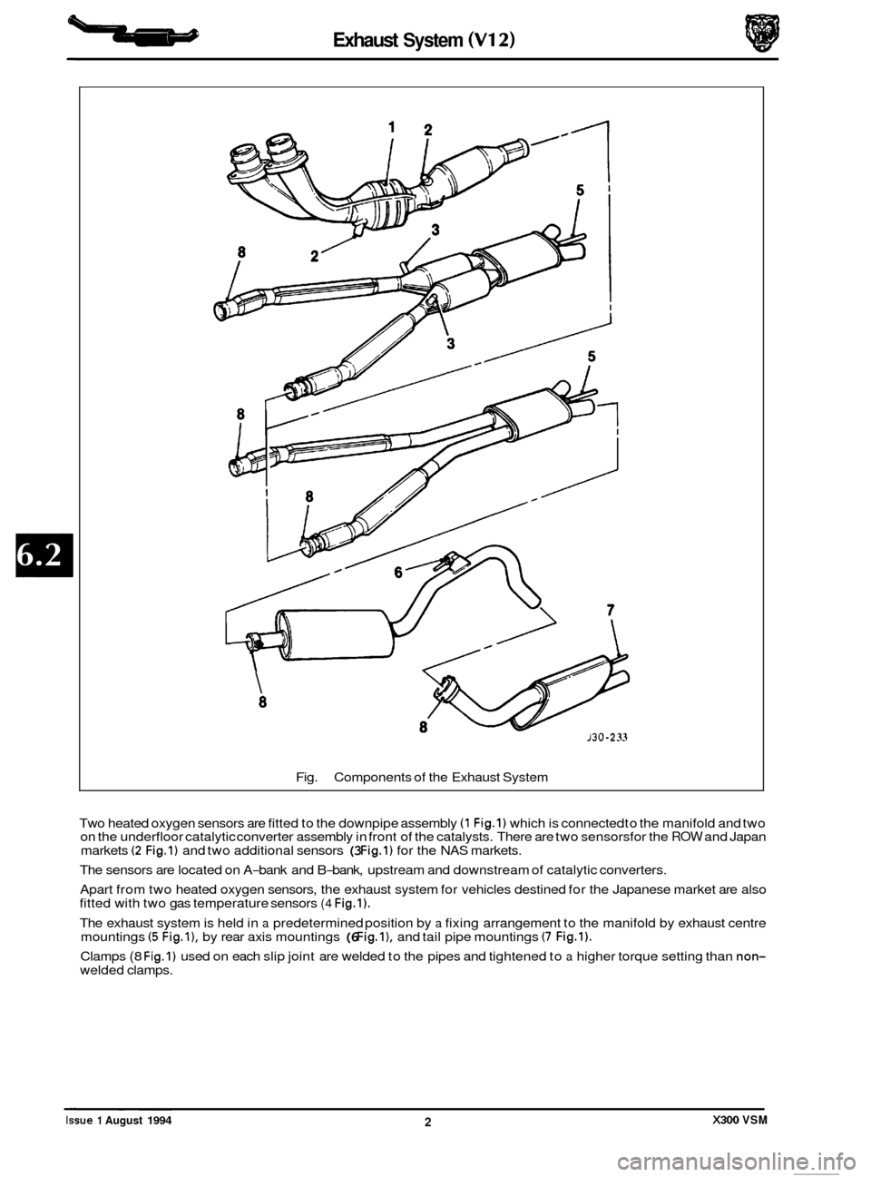
Fig.
P
Components of the Exhaust System
130 -2 33
Two heated oxygen sensors are fitted to the downpipe assembly (1 Fig.1) which is connected to the manifold and two
on the underfloor catalytic converter assembly in front of the catalysts. There are two sensorsfor the ROW and Japan
markets (2 Fig.1) and two additional sensors (3 Fig.1) for the NAS markets.
The sensors are located on A
-bank and B-bank, upstream and downstream of catalytic converters.
Apart from two heated oxygen sensors, the exhaust system for vehicles destined for the Japanese market are also
fitted with two gas temperature sensors
(4 Fig.1).
The exhaust system is held in a predetermined position by a fixing arrangement to the manifold by exhaust centre
mountings (5 Fig.l), by rear axis mountings (6 Fig.1). and tail pipe mountings (7 Fig.1).
Clamps (8 Fig.1) used on each slip joint are welded to the pipes and tightened to a higher torque setting than non- welded clamps. ~ ~~~
Issue 1 August 1994 2 X300 VSM
Page 112 of 521
Exhaust System (V12)
The exhaust system must be free of leaks, binding, grounding and excessive vibrations. These conditions are usually
caused by loose, broken, or misaligned clamps, shields, brackets, or pipes.
Should any
of the above mentioned conditions exist, check the exhaust system components and alignment.
Adjust and renew if necessary.
Do not attempt to service brackets clamps and insulators.
6.2.2 DIAGNOSIS AND TESTING
The standard exhaust system Diagnosis and Testing procedures are given in Section 6.1 (Exhaust System (AJ16)).
X300 VSM 3 Issue 1 August 1994
Page 113 of 521

4
Page 114 of 521
Manual Transmission & Clutch (AJ16)
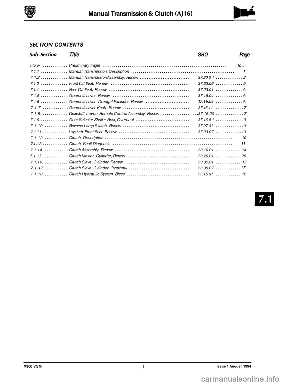
SECTlON CONTENTS
Sub-section Title SRO Page
i to iv ............ Preliminary Pages ................................................................ i to iii
7.1.1 ............. Manual Transmission. Description ...................................................... 1
7.1.2 ............. Manual Transmission Assembly, Renew ............................ 37.20.0 1 ............. 2
7.1.3
............. Front OilSeal. Renew .......................................... 37.23.06 ............. 5
7.1.4
............. Rear OilSeal. Renew ........................................... 37.23.01 ............. 6
7.1.5 ............. Gearshift Lever, Renew ......................................... 37.16.04 ............. 6
7.1.6 ............. Gearshift Lever Draught Excluder, Renew ......................... 37.16.05 ............. 6
7.1.7. ............ Gearshift Lever Knob. Renew .................................... 37.16.11 ............. 7
7.1.8. ............ Gearshifi Lever/ Remote Control Assembly, Renew .................. 37.16.20 ............. 7
7.1.9 ............. Gear Selector Shaft - Rear, Overhaul .............................. 37.16.4 1 ............. 9
7.1.10.
........... Reverse Lamp Switch. Renew .................................... 37.27.01 ............. 9
7.1.11 ............ Layshaft Front Seal. Renew ...................................... 37.23.07 ............. 9
7.1.12.
........... Clutch. Description .................................................................. 10
7.1.14.
........... Clutch Assembly, Renew ........................................ 33.10.01 ............ 14
7.1.15. ........... Clutch Master Cylinder, Renew .................................. 33.20.01 ............ 76
7.1.16. ........... Clutch Slave Cylinder, Renew ................................... 33.35.01 ............ 17
7.1.17.
........... Clutch Slave Cylinder, Overhaul ................................. 33.35.07 ............ 17
7.1.18. ........... Clutch Hydraulic System. Bleed .................................. 33.15.01 ............ 18
7 . 1 . 7 3 ............ Clutch. Fault Diagnosis .............................................................. 11
X300 VSM i Issue 1 August 1994
Page 115 of 521
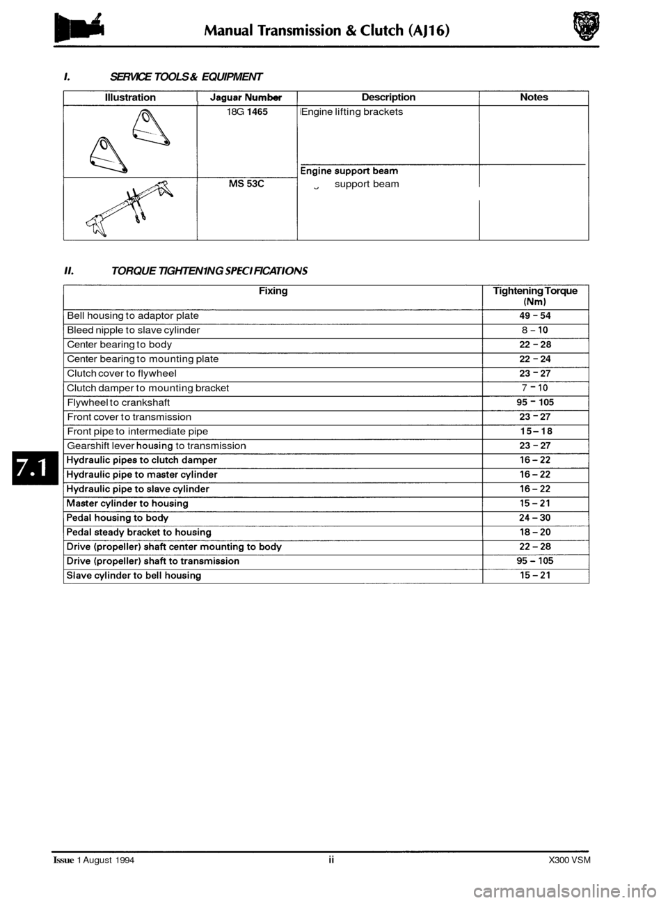
1. SERVICE TOOLS & EQUIPMENT
Illustration I JaauarNumber I -
18G 1465
Description Notes
Engine lifting brackets
Engine
fl support beam
11. TORQUE TIGHTEN1 NG SPEC1 FICA TIONS
Fixing Tightening Torque
(Nm)
49 - 54
8- 10
22 - 28
22
- 24
23 - 27
7 - 10
95 - 105
23
- 27
15
-18
23
- 27
Bell housing to adaptor plate
Bleed nipple to slave cylinder
Center bearing to body
Center bearing to mounting plate
Clutch cover to flywheel
Clutch damper to mounting bracket
Flywheel to crankshaft
Front cover to transmission
Front pipe to intermediate pipe
Gearshift lever
housing to transmission
Issue 1 August 1994 ii X300 VSM
Page 116 of 521
Manual Transmission & clutch (AJ16)
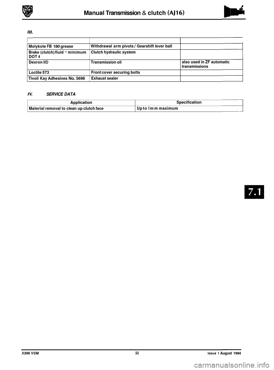
I Molykote FB 180 grease
Brake (clutch) fluid
- minimum
DOT 4
Dexron IID Transmission oil
Loctite
573
Tivoli Kay Adhesives No. 5696
Withdrawal arm pivots / Gearshift lever ball
Clutch hydraulic system
Front cover securing bolts
Exhaust sealer also used
in
ZF automatic
transmissions
Application
Material removal to clean up clutch face
IU SERVICE DATA
Specification
Up to lmm maximum
X300 VSM iii Issue 1 August 1994
Page 117 of 521

iv
Page 118 of 521
Manual Transmission & Clutch (AJ16)
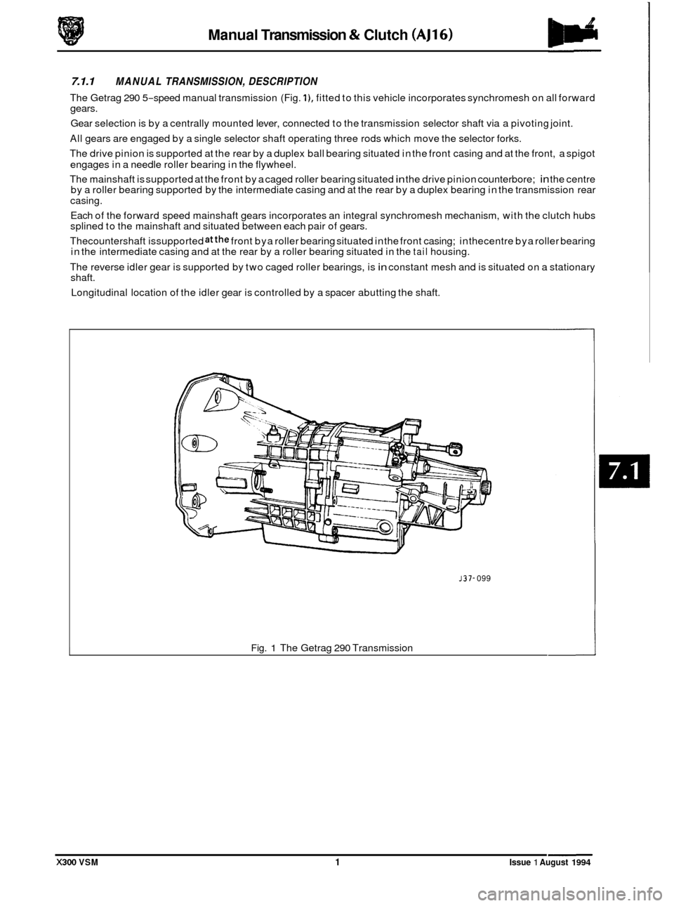
7.1.1 MANUAL TRANSMISSION, DESCRIPTION
The Getrag 290 5-speed manual transmission (Fig. I), fitted to this vehicle incorporates synchromesh on all forward
gears.
Gear selection is by a centrally mounted lever, connected to the transmission selector shaft via a pivoting joint.
All gears are engaged by a single selector shaft operating three rods which move the selector forks.
The drive pinion is supported at the rear by a duplex ball bearing situated in the front casing and at the front, a spigot
engages in a needle roller bearing in the flywheel.
The mainshaft is supported at the front by a caged roller bearing situated
in the drive pinion counterbore; in the centre
by a roller bearing supported by the intermediate casing and at the rear by a duplex bearing in the transmission rear
casing.
Each of the forward speed mainshaft gears incorporates an integral synchromesh mechanism, with the clutch hubs
splined to the mainshaft and situated between each pair of gears.
Thecountershaft issupported
atthe front bya roller bearing situated in the front casing; in thecentre bya roller bearing
in the intermediate casing and at the rear by a roller bearing situated in the tail housing.
The reverse idler gear is supported by two caged roller bearings, is
in constant mesh and is situated on a stationary
shaft.
Longitudinal location of the idler gear is controlled by a spacer abutting the shaft.
J37- 099
Fig. 1 The Getrag 290 Transmission
X300 VSM 1 Issue 1 August 1994
Page 119 of 521
Manual Transmission & Clutch (AJ16)
7.1.2 MANUAL TRANSMISSION ASSEMBLY, RENEW
SRO 37.20.01
. Disconnect the battery.
. Remove inlet manifold rear securing nuts.
. Remove injector harness mounting bracket.
. Fit lifting bracket 18G 1465 and secure with the nuts.
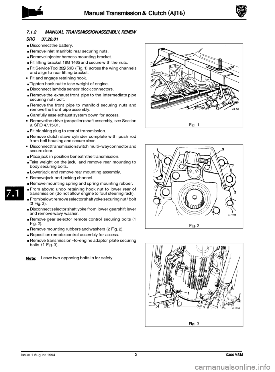
. Fit Service Tool MS 536 (Fig. 1) across the wing channels
Fit and engage retaining hook.
. Tighten hook nut to take weight of engine.
. Disconnect lambda sensor block connectors.
. Remove the exhaust front pipe to the intermediate pipe
securing nut / bolt.
. Remove the front pipe to manifold securing nuts and
remove the front pipe assembly.
. Carefully ease exhaust system down for access.
Remove the drive (propeller) shaft assembly, see Section
. Fit blanking plug to rear of transmission.
. Remove clutch slave cylinder complete with push rod
Disconnect transmission switch multi-way connector and
. Place jack in position beneath the transmission.
. Take weight on the jack, and remove rear mounting to
. Lower jack and remove rear mounting assembly.
Remove jack and jacking channel.
. Remove mounting spring and spring mounting rubber.
. From above: undo retaining hook nut to lower rear of
transmission (do not allow engine to foul steering rack).
. From below: remove selector shaft yoke securing nut / bolt (3 Fig. 2).
. Disconnect selector shaft yoke from lower gearshift lever
and remove wavy washer.
. Remove gear selector remote control securing bolts (1 Fig. 2).
. Remove mounting rubbers and washers (2 Fig. 2).
. Reposition remote control assembly for access.
. Remove transmission-to-engine adaptor plate securing
and
align to rear lifting bracket.
9, SRO 47.15.01.
from bell housing and secure clear.
secure clear.
body securing bolts.
bolts
(1 Fig. 3).
N.&: Leave two opposing bolts in for safety.
Fig. 1
Fig.
2
Fig. 3 ~ ~ ~~ ~
Issue 1 August 1994 2 X300 VSM
Page 120 of 521
Manual Transmission & Clutch (AJ16)
. Remove front clamp from unit lift.
. Raise / lower unit with jack, no stands.
. Traverse lift under ramp and take weight of transmission.
. Adjust jacking platform angles to suit transmission.
. Adjust side and rear clamps to suit transmission and tighten clamp wing nuts.
. Fit the safety chain assembly to left hand arm of lift, and secure with peg.
Pass safety chain over transmission and engage in front arm of lift. Tighten the safety chain adjuster.
. Remove remaining transmission to adaptor plate securing bolts and carefully lower transmission from engine.
. Remove transmission from ramp area.
. Remove clutch release bearing assembly from release lever.
. Remove clutch release lever retaining clip and remove lever.
. Remove release lever pivot pin.
Remove transmission switch.
. Remove rear mounting spring retainer securing nut.
. Reposition selector shaft pin cover.
0
Remove rear mounting spring retainer and remove rear mounting assembly.
Remove selector shaft yoke to selector shaft retaining pin and remove the yoke.
. Remove slave cylinder securing studs.
. Remove the transmission from the unit lift.
. Remove transmission drain plug and allow to drain, refit
the drain plug.
Fit new transmission to unit lift.
Fill transmission with oil and refit the level plug.
. Clean components and mating faces.
. Fit the slave cylinder mounting studs.
. Lubricate the selector output shaft.
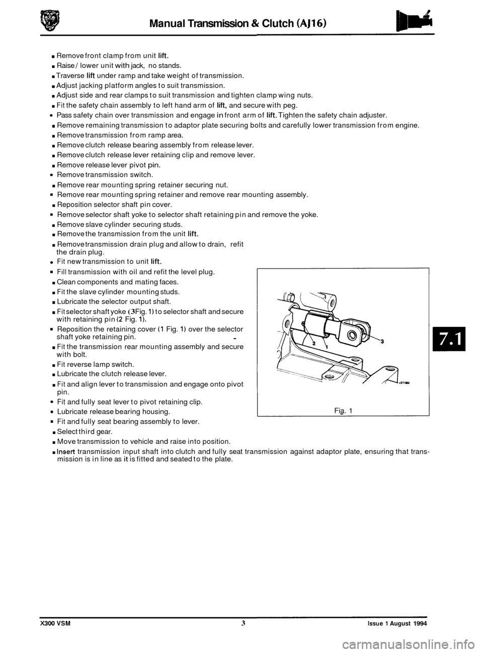
. Fit selector shaft yoke (3 Fig. 1) to selector shaft and secure
with retaining pin (2 Fig. 1).
Reposition the retaining cover (1 Fig. 1) over the selector
shaft yoke retaining pin. -
. Fit the transmission rear mounting assembly and secure
with bolt.
. Fit reverse lamp switch.
. Lubricate the clutch release lever.
. Fit and align lever to transmission and engage onto pivot
pin.
Fit and fully seat lever to pivot retaining clip.
= Lubricate release bearing housing.
9 Fit and fully seat bearing assembly to lever.
. Select third gear.
. Move transmission to vehicle and raise into position.
Fia. 1
. Insert transmission input shaft into clutch and fully seat transmission against adaptor plate, ensuring that trans- mission is in line as it is fitted and seated to the plate.
X300 VSM 3 Issue 1 August 1994