ECU JAGUAR XJ6 1994 2.G Workshop Manual
[x] Cancel search | Manufacturer: JAGUAR, Model Year: 1994, Model line: XJ6, Model: JAGUAR XJ6 1994 2.GPages: 521, PDF Size: 17.35 MB
Page 299 of 521
Body Components & Trim #ib
13.6 GLAZING (FIXED)
13.6.1 Glazing (Fixed), Description
The fixed glazing comprises internal and external driving mirrors, sunvisor mirror and rear quarter light glass; see Ap- pendix A4, Body Components and Trim for details of the windscreen and rear screen glazing.
13.6.2 Interior Mirror, Renew
. Disconnect vehicle battery ground lead.
. Rotate mirror stem approximately one quarter turn clock- wise to release stem from spring contact on windscreen
boss.
. Disconnect mirror harness.
To refit, locate mirror stem base on windscreen boss with
stem parallel to top of windscreen, ie one quarter turn dis- placed from normal position; apply firmly over boss and
turn anti-clockwise to lock stem on windscreen boss.
. Reconnect mirror harness.
13.6.3
. Disconnect vehicle battery ground lead.
. Lower the sunvisor.
. Raise the sunvisor cover and remove the lenses.
Remove the screws securing the mirror to the sunvisor
and remove the mirror.
. To refit, carry out reversal of the above procedure, taking
care to correctly locate switch and bulb holders priortose-
curing the mirror.
Sun Visor Mirror Assembly, Renew
13.6.4 Exterior Mirror, Renew
= Disconnect vehicle battery ground lead.
Remove door trim pad veneer panel and upper trim pad.
9 Remove the cheater by sliding off.
. Remove mirror fixings.
. Disconnect the mirror harness block connectors.
. Remove the mirror securing screws and remove the mir-
ror assembly.
. To refit, carry out reversal of the above procedure.
13.6.5 Exterior Mirror Glass, Renew
. Switch ignition on and position the mirrorto inboard posi-
. Disconnect vehicle battery ground lead.
. Slide assembly outboard and pull outwards.
. To refit, carry out reversal of the above procedure.
tion.
Issue 1 August 1994 44 X300 VSM
Page 303 of 521
Body Components & Trim a
13.8 SEATING AND SEAT BELTS
13.8.1 Seating, Description
The front seats are available in a range of materials consisting of sculptured fabric / leather, leather, sports cloth / leather, embossed leather / leather and autolux. Both seats are available as 'manual', ie manually adjustable with elec- tric rise and fall, manual height adjustment headrests, 'power', ie 12-way electric adjustment, 'power with memory', ie memory controlled, 12-way electric adjustment of seat, steering column and exterior rear view mirrors and 'heated',
ie with integral heating.
Front seats are based on a non
-handed, one-piece frame which includes cushion and squab frames and seat adjuster
mechanisms. The seat switchpacks (powerseats) are fitted to the outboard side of driver and passenger seats; on 'man- ual'seats, the seat height adjustment switch is similarly located. Seat control modules SCMs are contained within the
seat assemblies. The seats are secured through four mounting points to the vehicle floor.
Rear seats are of the bench type with
full width removable cushion and individual seat squabs.
Electrical components installed on the heel board below the rear passenger seat are protected
by two covers secured
by two locating brackets on the floor and by two latches on the cover. The latches are released by pushing down on
the two recesses in the top edge of the cover.
13.8.2 Front Manual Seat, Renew
. Disconnect vehicle battery ground lead.
. Disconnect electrical connections as required.
. Remove the seat forward fixings.
Move the seat fully forward.
. Remove the rear fixing / slide covers.
. Remove the seat rear fixings.
. Reposition seat for access and remove seat from vehicle.
. To refit seat, carry out reversal of above procedure.
13.8.3
. Disconnect vehicle battery ground lead.
. Move the seat fully forward to gain access to squab back
Remove squab side fixings, disconnect lamp harness and
. To refit, carry out reversal of the above procedure.
Front Seat (Power Operated) Squab Back
Cover, Renew
cover outer fixings.
remove squab back cover.
13.8.4
. Position seat as required for access.
. Disconnect vehicle battery ground lead.
. Release sound insulation retainers and displace insula-
. Remove SCM cover, move SCM aside and remove seat
. Remove the seat forward fixings and move the seat fully
. Remove the seat rearward fixing covers and remove the
. Disconnect multi-plugs, seat switch and motor harness to
. Release harness tie strap and remove seat assembly from
Front Seat (Power Operated), Renew
tion.
switch
multi-plug from its mounting bracket.
forward. seat rearward fixings.
SCM.
vehicle.
. To refit, carry out reversal of the above procedure, ensur- ing that fixings are tightened to the correct torque.
Issue 1 August 1994 48 X300 VSM
0
0
0
Page 307 of 521

Body Components & Trim
0 13.8.1 1 Front Seat Belt Buckle Unit, Renew
. Disconnect vehicle battery ground lead.
. Remove the front seat cushion.
. Disconnect cable connector and remove cable into seat
frame.
. Remove securing bolt, buckle unit and wavy washer.
. To refit, carry out reversal of the above procedure.
13.8.12 Front Seat Belt, Renew
. Position the front seat for access.
. Disconnect vehicle battery ground lead.
. Release 'B' post upper trim and belt aperture cover.
. Remove cover from seat belt upper fixing.
. Removeseat belt upper fixing and releaseseat belt anchor
. Lower the upper trim pad with seat belt onto the seat.
Remove 'B' post lower trim.
. Remove seat belt lower fixing, disconnect anchor plate
and remove wavy washer.
. Release upper trim pad from seat belt. Remove upper
guide fixings at 'B' post.
. Remove seat belt reel fixings and remove reel and belt as- sem bly.
. Refit seat cushion.
Secure seat belt reel to the specified torque.
Fit and secure upper guide plate to 'B' post.
Pass the seat belt through the upper trim pad.
. Fit wavy washerto lower anchor,fit lower anchor plate and
. Refit lower 'B' post trim panel.
. Refit upper 'B' post trim panel.
from
height adjuster; remove wavy washer.
0
nut; tighten to specified torque.
Place wavy washer
on height adjuster stud, fit belt upper
anchor and nut; tighten to specified torque.
. Fit plastic cover and split finisher.
13.8.13 Rear Inertia Seat Belt, Renew
= Remove seat cushion, rear seat squab and rear parcel tray.
. Remove foam pad from rear shelf and remove seat belt
. Remove buckle assembly, washers and spacers.
. Remove side seat belt buckle and the lower anchorage
. Move the belt aside and remove the upper spacer.
Remove theseat belt bracket/ body fixing and remove reel
= Remove seat belt reel / securing bracket fixings.
. Remove the reel and belt assembly.
. To refit, carry out reversal of the above procedure.
0 buckle bolt.
belt.
/ bracket assembly.
m
Issue 1 August 1994 52 X300 VSM ~~
Page 308 of 521
Body Components & Trim -
0 13.8.14 Rear, Center, Static Seat Belt, Renew
Remove rear seat cushion.
Remove seat belt buckle bolt and remove buckle.
Remove washers, spacers and side seat belt buckle.
Remove
center lap strap buckle and seat belt strap secur- ing bolt.
Remove the strap and buckle assembly.
Remove washers, spacers and side seat belt buckle.
To refit, carry out reversal of the above procedure.
X300 VSM 53 Issue 1 August 1994
Page 315 of 521
Climate Control Systems
0 Because HFC 134A is fully recycleable it may be 'cleaned' by the recovery equipment and re-used following
removal from a system.
0 Leak tests should only be carried out with an electronic analyzer which is dedicated to HFC 134A. Never use a CFC 12 analyzer or naked flame type.
0 Do not attempt to 'guess' the amount of refrigerant in a system, always recover and recharge with the correct
charge weight. In this context do not depress the charge or discharge port valves to check for the presence of
refrigerant.
14.1.3 Handling Lubricating Oil
0 Avoid breathing lubricant mist, it may cause irritation to your respiratory system.
0 Always decant fresh oil from a sealed container and do not leave oil exposed to the atmosphere for any reason
other than to fill or empty a system. PAG oil is very hygroscopic (absorbs water) and will rapidly become con-
taminated by atmospheric moisture.
PAG oil is
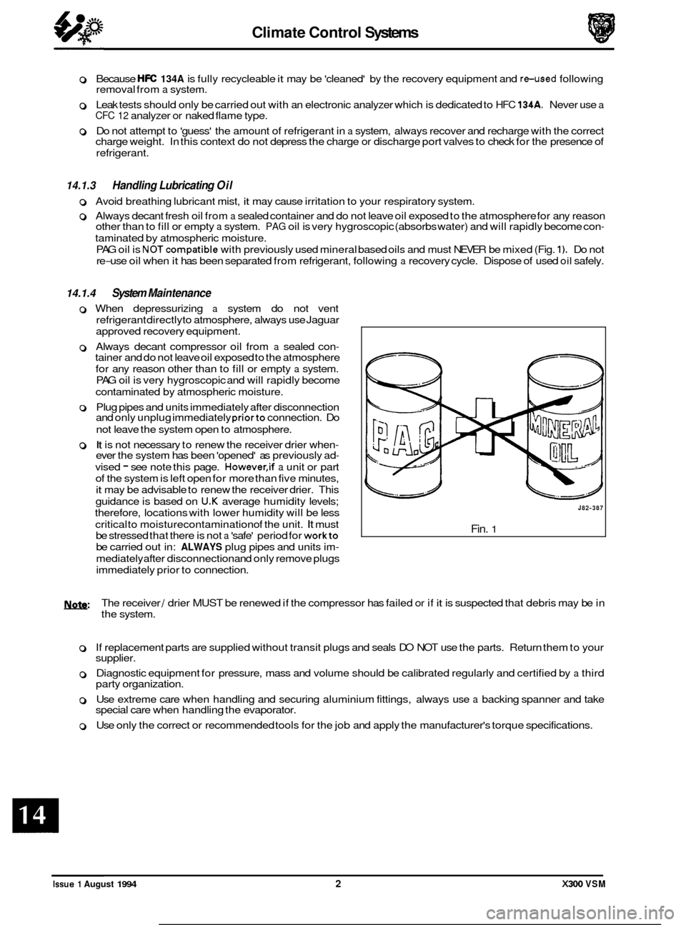
NOTcompatible with previously used mineral based oils and must NEVER be mixed (Fig. 1). Do not
re
-use oil when it has been separated from refrigerant, following a recovery cycle. Dispose of used oil safely.
14.1.4 System Maintenance
0 When depressurizing a system do not vent
refrigerant directlyto atmosphere, always use Jaguar
approved recovery equipment.
0 Always decant compressor oil from a sealed con- tainer and do not leave oil exposed to the atmosphere
for any reason other than to fill or empty
a system.
PAG oil is very hygroscopic and will rapidly become
contaminated by atmospheric moisture.
0 Plug pipes and units immediately after disconnection
and only unplug immediately priorto connection. Do
not leave the system open to atmosphere.
0 It is not necessary to renew the receiver drier when- ever the system has been 'opened' as previously ad-
vised - see note this page. However,if a unit or part
of the system is left open for more than five minutes,
it may be advisable to renew the receiver drier. This
guidance is based on
U.K average humidity levels;
therefore, locations with lower humidity will be less
critical to moisturecontamination of the unit.
It must
be stressed that there is not
a 'safe' period for workto
be carried out in: ALWAYS plug pipes and units im-
mediately after disconnection and only remove plugs
immediately prior to connection.
J82-387
Fin. 1
U: The receiver / drier MUST be renewed if the compressor has failed or if it is suspected that debris may be in
the system.
0 If replacement parts are supplied without transit plugs and seals DO NOT use the parts. Return them to your
supplier.
0 Diagnostic equipment for pressure, mass and volume should be calibrated regularly and certified by a third
party organization.
0 Use extreme care when handling and securing aluminium fittings, always use a backing spanner and take
special care when handling the evaporator.
0 Use only the correct or recommended tools for the job and apply the manufacturer's torque specifications.
Issue 1 August 1994 2 X300 VSM
Page 326 of 521
Climate Control Systems
0 14.9 GENERAL SYSTEM PROCEDURES
14.9.1 Leak Test
Faults associated with low refrigerant charge weight and low pressure may be caused by leakage. Leaks traced to
mechanical connections may be caused by torque relaxation or joint face contamination. Evidence of oil around such
areas is an indicator of leakage. When checking for non visible leaks use only
a dedicated HFC 134A electronic analyzer
and apply the probe all round the joint / connection.
Should a leak betraced to a joint,checkthatthefixing issecuredtothecorrecttightening torque before any other action
is taken.
Do not forget to check the compressor shaft seal and evaporator.
CAUTION : Never use a dedicated CFC 12 or naked flame type analyzer.
14.9.2 Charge Recovery (System depressurization)
The process of HFC 134A recovery will depend on the basic characteristics of your chosen recovery/ recycle I recharge
equipment, therefore, follow the manufacturer's instructions carefully.
Remember that compressor oil may be drawn
out of the system by this process, take note of the quantity recovered
so that it may be replaced.
CAUTION: Observe all relevant safety requirements.
Wear suitable eye and skin protection
Do not mix HFC 134A with CFC 12. Do not vent refrigerant directly to atmosphere and always use Jaguar approved recovery I recycle I re- charge equipment.
Take note of the amount of recovered refrigerant, it will indicate the state of the system. 0
14.9.3 Evacuating the System
This process, the removal of unwanted air and moisture, is critical to the correct operation of the air conditioning sys-
tem. The specific procedures will vary depending on the individual characteristics of your chosen recovery I recycle / recharge equipment and must be carried out exactly in accordance with the manufacturers instructions. However,
it is recommended that the initially only the HIGH side valve be opened at the start of the procedure. After a short time a small depression should be seen on the LOW side, at which point the LOW side valve may be opened and the evacu- ation process completed. If a vacuum is not registered on the LOW side it may indicate that the expansion valve is
jammed closed or that the system is blocked. This simple check may save time and effort when the system is re- charged.
Moisture can be highly destructive and may cause internal blockages due to freezing, but more importantly, water sus- pended in the PAG oil will damage the compressor. Once the system has been opened for repairs, or the refrigerant
charge recovered, all traces of moisture MUST be removed before recharging.
14.9.4
The amount of oil drawn out during a recovery procedure will be dependent on the state of the system and the rate
of recovery. The quantity will be approximately 30 to 40 ml; this may vary, and the figure is given only for guidance.
The oil separator vessel in the recovery equipment must be clean and empty
at the start of the process so that the quan- tity of oil which is drawn out may be accurately measured.
Oil may be added by three methods,
1 and 2 being direct into the system and 3 with the compressor off the vehicle;
1. Via the recovery I recycle 1 recharge station.
2. Proprietary oil injector.
Adding Lubricating Oil - Compressor Related
1ynfa: Equipment manufacturer's instructions must be adhered to when using direct oil introduction.
3. Directly into the original, or new unit, because of rectification work to the existing compressor, or the need to fit a new compressor.
Original
From an existing compressor, drain the oil into a measuring cylinder and record the amount. Flush the unit out
with fresh PAG oil and drain thoroughly, Replenish the compressor with the same amount of PAG oil that was
originally drained out and immediately plug all orifices ready for refitting to the vehicle.
X300 VSM 13 Issue 1 August 1994
Page 343 of 521

15.1.2 Handling Undeployed Modules
The electrically-activated airbag module contains sodium azide and sodium nitrate which are poisonous and
extremely flammable substances.
Their contact with acid, water or heavy metals may produce harmful and irritating gases or combustible compounds.
The airbag module is
non-serviceable and must not be dismantled, punctured, incinerated or welded.
WARNING: DO NOT ATTEMPT ANY REPAIRS TO THE AIRBAG MODULE.
Never measure the resistance of the airbag module, as this may cause the airbag to deploy. Suspect modules must be returned to Jaguar Cars Ltd. or their importer for replacement.
Tampering or mishandling can result in personal injury.
Keep away from heat, sparks and open flames. Do not store
at temperatures exceeding 93O Celsius (200OF).
Keep away from electrical equipment as electrical contact may cause ignition.
Do not drop or impact airbag module.
Always position module 'cover
-up'.
Ensure that the connector is protected to prevent damage.
J76-1058
Fig. 1 The Driver-side Airbag
Store modules in a secure lockable cabinet.
Never position projectile material over the undeployed airbag as this can cause injury in the event of inadvertent
deployment.
Page 348 of 521
(continued from previous page)
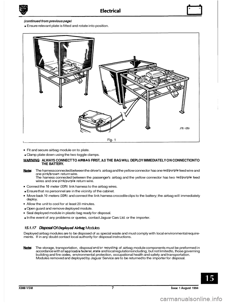
. Ensure relevant plate is fitted and rotate into position.
0
Fig. 1
Fit and secure airbag module on to plate.
. Clamp plate down using the two toggle clamps.
WARNING: ALWAYS CONNECT TO AlRBAG FIRST, AS THE BAG WILL DEPLOY IMMEDIATELY ON CONNECTION TO
THE BATTERY.
m: The harness connected between the driver's airbag and the yellow connector has one red/purple feed wire and
one pinkbrown return wire.
The harness connected between the passenger's airbag and the yellow connector has two red/purple feed
wires and one pinldpurple return wire.
rn Connect the 10 meter (33ft) link harness to the airbag wires.
. Ensure that no personnel are in the vicinity of the cabinet.
Move back 10 meters (33ft) and connect the link harness crocodile clips to the battery; the airbag will immediately
Allow the unit to cool for at least 20 minutes.
. Open guard and remove deployed module.
Seal deployed module in plastic bag ready for disposal.
. In the event of any problems or queries, contact Jaguar Cars Ltd. or the importer.
deploy.
15.1.17 Disposal Of Deploytd Airbag Modules
Deployed airbag modules are to be disposed of as special waste and must comply with local environmental require- ments. If in any doubt contact local authority for disposal instructions.
W. The storage, transportation, disposal and/or recycling of airbag module components must be preformed in
accordance with all appIicablefedera1,state and local regulations including, but not limited to, those governing
building and fire codes, environmental protection, occupational health and safety and transportation.
Modules removed and deployed by Jaguar Service are to be returned to the importer for disposal.
X300 VSM 7 Issue 1 August 1994
Page 350 of 521
31
30
29
28 27
26
4 26 24 21 23 22 7 20 19 18 18 17 8
a
10
11
12
13
14
1s
1M-137
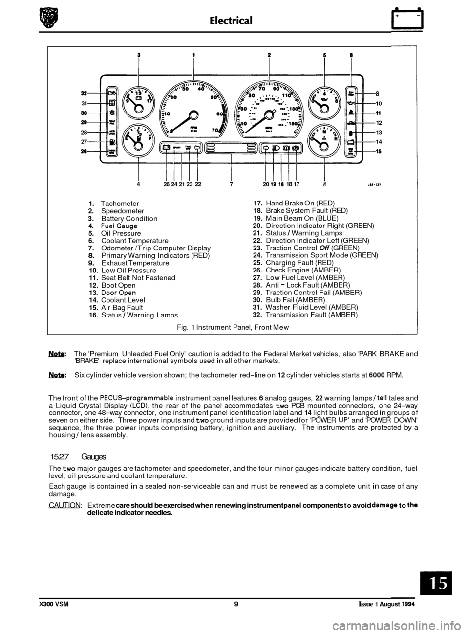
1. Tachometer 2. Speedometer
3. Battery Condition 4. FuelGauge 5. Oil Pressure 6. Coolant Temperature 7. Odometer /Trip Computer Display 8. Primary Warning Indicators (RED) 9. Exhaust Temperature 10. Low Oil Pressure 11. Seat Belt Not Fastened 12. Boot Open 13. DoorOpen 14. Coolant Level 15. Air Bag Fault 16. Status / Warning Lamps
17. Hand Brake On (RED) 18. Brake System Fault (RED)
19. Main Beam On (BLUE) 20. Direction Indicator Right (GREEN) 21. Status / Warning Lamps 22. Direction Indicator Left (GREEN) 23. Traction Control Off (GREEN) 24. Transmission Sport Mode (GREEN) 25. Charging Fault (RED) 26. Check Engine (AMBER)
27. Low Fuel Level (AMBER) 28. Anti - Lock Fault (AMBER) 29. Traction Control Fail (AMBER) 30. Bulb Fail (AMBER) 31. Washer Fluid Level (AMBER) 32. Transmission Fault (AMBER)
Fig.
1 Instrument Panel, Front Mew
w: The 'Premium Unleaded Fuel Only' caution is added to the Federal Market vehicles, also 'PARK BRAKE and
'BRAKE' replace international symbols used in all other markets.
m: Six cylinder vehicle version shown; the tachometer red-line on 12 cylinder vehicles starts at 6000 RPM.
The front of the
PECUSprogrammable instrument panel features 6 analog gauges, 22 warning lamps /tell tales and
a Liquid Crystal Display (LCD), the rear of the panel accommodates two PCB mounted connectors, one 24-way
connector, one 48-way connector, one instrument panel identification label and 14 light bulbs arranged in groups of
seven on either side. Three power inputs and two ground inputs are provided for 'POWER UP' and 'POWER DOWN'
sequence, the three power inputs comprising battery, ignition and auxiliary. The instruments are protected by a
housing
/ lens assembly.
15.2.7 Gauges
The two major gauges are tachometer and speedometer, and the four minor gauges indicate battery condition, fuel
level, oil pressure and coolant temperature.
Each gauge is contained
in a sealed non-serviceable can and must be renewed as a complete unit in case of any
damage.
CAUTION: Extreme care should be exercised when renewing instrument pand components to avoid damago to the delicate indicator needles.
X300 VSM 9 Issue 1 August 1994
Page 380 of 521
86.52.01
86.91 -83
19.75.21
86.80.24
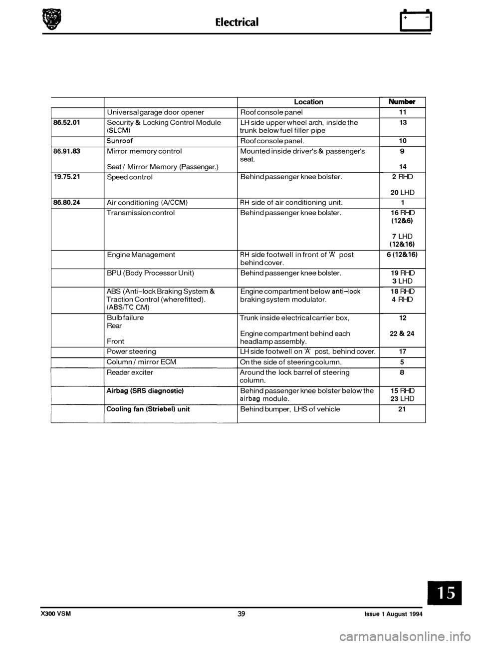
Universal garage door opener
Security
& Locking Control Module
(SLCM)
Sunroof
Mirror memory control
Seat
/ Mirror Memory (Passenger.)
Speed control
Air conditioning
(NCCM)
Transmission control
Engine Management
BPU (Body Processor Unit)
ABS (Anti
-lock Braking System &
Traction Control (where fitted).
(ABS/TC CM)
Bulb failure
Rear
Front
I Power steering
I Column / mirror ECM
Reader exciter
Location
Roof console panel
LH side upper wheel arch, inside the
trunk below fuel filler pipe
Roof console panel.
Mounted inside driver's
& passenger's
seat.
Behind passenger knee bolster.
RH side of air conditioning unit.
Behind passenger knee bolster.
RH side footwell in front of 'A' post
behind cover.
Behind passenger knee bolster.
Engine compartment below
anti-lock
braking system modulator.
Trunk inside electrical carrier box,
Engine compartment behind each
headlamp assembly.
LH side footwell on
'A' post, behind cover.
On the side of steering column.
Around the lock barrel of steering
column.
Behind passenger knee bolster below the
airbag module.
Behind bumper, LHS of vehicle
Numb
11
13
10
9
14
2
RHD
20 LHD
1
16
RHD
(1 2&6)
7 LHD
(12&16)
6 (12&16)
19 RHD
3 LHD
18 RHD
4 RHD
12
22
& 24
17 5
8
15 RHD
23 LHD
21
X300 VSM 39 issue 1 August 1994