ECU JAGUAR XJ6 1994 2.G Workshop Manual
[x] Cancel search | Manufacturer: JAGUAR, Model Year: 1994, Model line: XJ6, Model: JAGUAR XJ6 1994 2.GPages: 521, PDF Size: 17.35 MB
Page 401 of 521
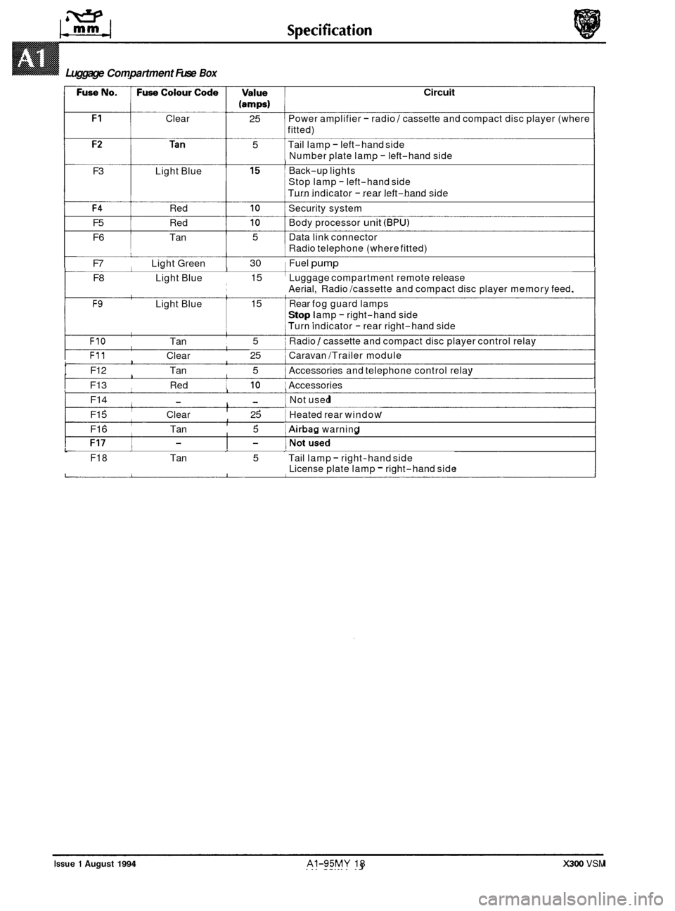
Clear
(amps) 1
Circuit
I
25 5 Power amplifier - radio / cassette and compact disc player (where
fitted)
Tail lamp
- left-hand side
Number plate lamp
- left-hand side I Back-up lights
Stop lamp
- left-hand side
Turn indicator
- rear left-hand side
F3 Light Blue
F4 Red 10 Security system
F5 Red 10 Body processor unit (BPU)
F6 Tan 5 Data link connector
F7 Light Green 30 Fuel pump
F8 Light Blue 15 Luggage compartment remote release
F9 Light Blue 15 i Rear fog guard lamps
Radio
telephone (where fitted)
1
Aerial, Radio /cassette and compact disc player memory feed.
Stop lamp
- right-hand side
1 Turn indicator - rear right-hand side I.
I FIO Tan 5 i Radio / cassette and compact disc player control relay
F11 Clear 25 1 Caravan /Trailer module I
t F12 Tan 5 ~ Accessories
and telephone control relay I I
I I I F13 Red 10 ~ Accessories 1 1 I I F14 - - I Not used 1 I I F15 Clear 25 1 Heated
rear window I I I F16 Tan 5 1 Airbag warning
Luggage Compartment Fuse Box
Issue 1 August 1994 AI-95MY 18 X300 VSM
L F18 Tan 5 Tail lamp - right-hand side
License plate lamp - right-hand side
Page 409 of 521
Routine Maintenance
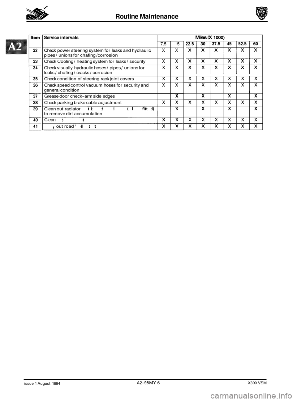
Service intervals
Check power steering system for leaks and hydraulic
pipes
/ unions for chafing /corrosion
Check Cooling
/ heating system for leaks / security
Check visually hydraulic hoses
/ pipes / unions for
leaks
/ chafing / cracks / corrosion
Check condition of steering rack joint covers
Check speed control vacuum hoses for security and
general condition
Grease door check
-arm side edges
Check parking brake cable adjustment
Miles (X 1000)
7.5 15
X X
xx
xx
xx
xx
X
xx
xxxxxx
xxxxxx
x
X X X
xxxxxx
X X X
xxxxxx
XIX x x x
-
Clean out radiator matrix and condenser (where fitted)
to remove dirt accumulation
Clean antenna mast
xx
Carry out road / roller test Ix
i
0
0
0
X
x
issue 1 August 1994 A2-95MY 6 X300 VSM
Page 415 of 521
General Fitting Instructions
Pressordrifttheseal in tothefull depthofthe housing ifthe housing is shouldered,orflush withthefaceofthe housing
where no shoulder is provided.
Note: Careless fitting of oil seals, which can result in damage to the seal and sealing surfaces, accounts for most
cases of failure of seals. Care in fitting is essential
if good results are to be obtained.
A3.2.7 joints And joint Faces
Remove all traces of old jointing materials prior to reassembly. Inspect joint faces for scratches or burrs and remove
with a fine file or oilstone; do not allow swarf or dirt to enter tapped holes or enclosed parts. Blow out any pipes, chan- nels or crevices with compressed air, refitting or renewing any 0-rings or seals which have been displaced by the com- pressed air.
Always use the specified gaskets. Use jointing compound only when recommended, otherwise fit joints dry. When
jointing compound is used, apply in
a thin film to metal surfaces; take great care to prevent it from entering oilways, pipes or blind tapped holes.
A3.2.8
Before removing a hose from the brake or power steering systems, thoroughly clean the end fittings and the area sur- rounding them. Obtain blanking caps beforedetaching hosefittings,sothat portscan becovered to excludedirt. Clean
the hose externally and blow through with compressed air. Examine the hose carefully for cracks, separation of plies,
security of end fittings and external damage. Reject any hose found to be faulty. When refitting the hose, ensure that
no unnecessary bends are introduced and that the hose is not twisted before or during tightening of union nuts.
Do not store hydraulic fluid in an unsealed container because it will absorb water. Fluid in this condition would be dan- gerous to use due to a lowering of its boiling point. Do not allow hydraulic fluid to be contaminated with mineral oil,
or use a container which has previously contained mineral oil.
Do not re-use fluid bled from the system. Always use clean brake fluid, or a recommended alternative, to clean the
hydraulic components. Fit a blanking cap to the hydraulic union and
a plug to its mating socket, after removal from
the vehicle, to prevent ingress of dirt. Absolute cleanliness must be observed with hydraulic components at all times.
After any work has been performed on hydraulicsystems, inspect carefully for leaks underneath the car while a second
operator applies maximum pressure to the brakes (with the engine running) and operates the steering.
Hydraulic Flexible Pipes And Hoses
A3.2.9 Metric
Bolt Identification
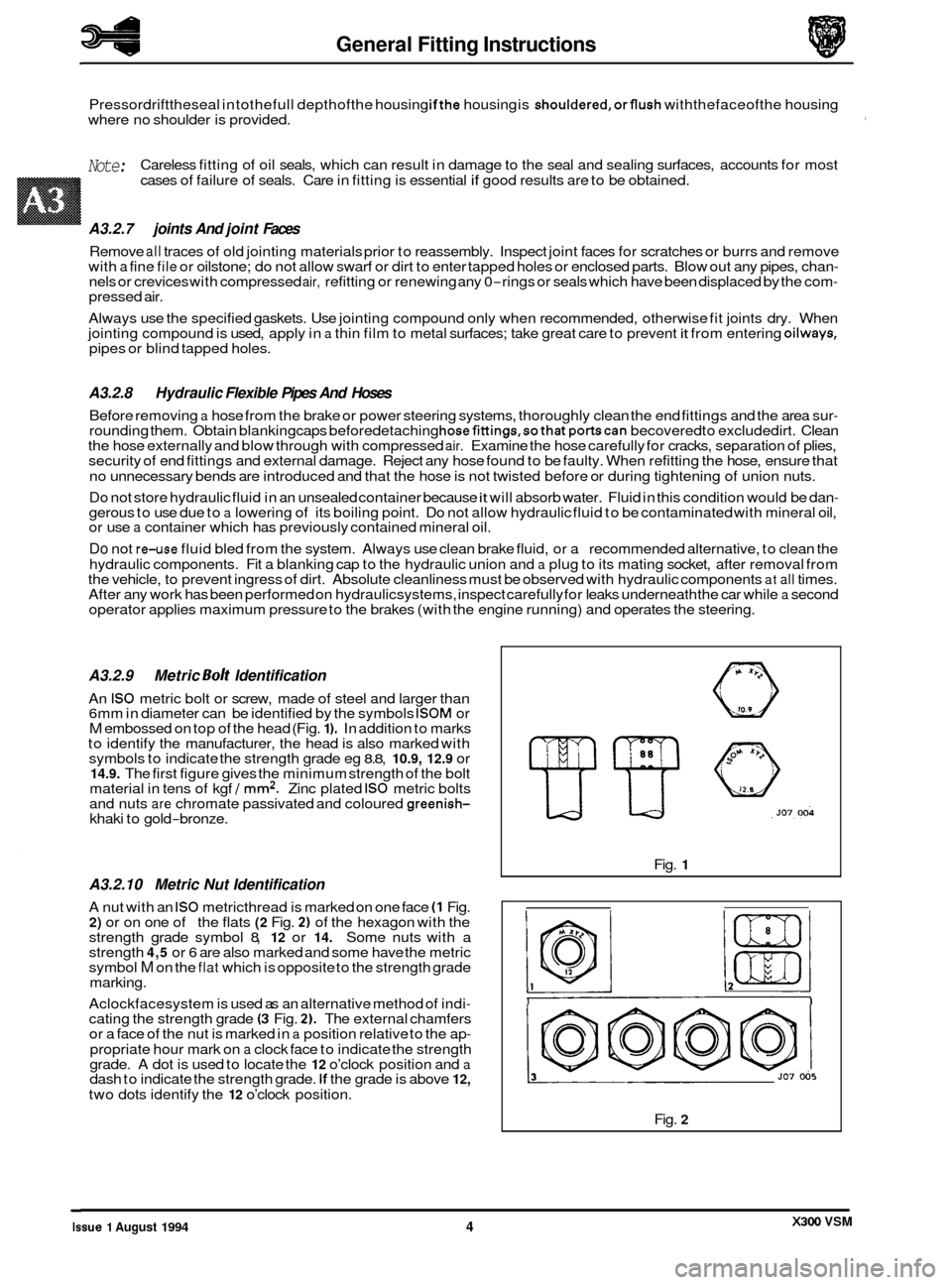
An IS0 metric bolt or screw, made of steel and larger than
6mm in diameter can be identified by the symbols ISOM or M embossed on top of the head (Fig. 1 ). In addition to marks
to identify the manufacturer, the head is also marked with
symbols to indicate the strength grade eg
8.8, 10.9, 12.9 or 14.9. The first figure gives the minimum strength of the bolt
material in tens of kgf / mm2. Zinc plated IS0 metric bolts
and nuts are chromate passivated and coloured greenish- khaki to gold-bronze.
A3.2.10 Metric Nut Identification
A nut with an IS0 metricthread is marked on one face (1 Fig. 2) or on one of the flats (2 Fig. 2) of the hexagon with the
strength grade symbol 8, 12 or 14. Some nuts with a
strength 4,5 or 6 are also marked and some have the metric
symbol M on the flat which is opposite to the strength grade
marking.
Aclockfacesystem is used as an alternative method of indi
- cating the strength grade (3 Fig. 2). The external chamfers
or a face of the nut is marked in a position relative to the ap-
propriate hour mark on a clock face to indicate the strength
grade. A dot is used to locate the 12 o’clock position and a dash to indicate the strength grade. If the grade is above 12,
two dots identify the 12 o’clock position. Fig.
1
I I
Fig. 2
X300 VSM Issue 1 August 1994 4
Page 468 of 521

A4.6.6.2 Body-side Moulding - Fitfed Condition
A4.6.6 BODY-SIDE MOULDINGS
A4.6.6.1 Introduction
There are two types of moulding fitted to the standard wheelbase sedan.
The lower moulding is ‘self
-locating‘ on the body / door lower feature line and therefore provides a fixed datum for
the location of the upper moulding (wherefitted). Replacement lower mouldings will be supplied in a primed condition
and therefore must be finished in accordance with A4.6.3, this section.
Location Finish Application Fixing method
Polished stainless steel Daimler / VDP Adhesive
tape
Lower Bodv
color All models Adhesive
tape
Upper ~~
J76-la23
1 . Adhesive
tape 2. Moulding, Daimler / VDP. 3. Moulding, All models
Fig.
1
144.6.6.3 Fitting process
. ‘Spirit wipe’ appropriate body panel and where appropriate protect against damage.
. Gently warm body panel and moulding using infa-red lamp or similar.
. Lower moulding - align to body feature and other mouldings if appropriate, and secure into position.
. Upper moulding - align to lower moulding for distance (Fig. 1) and parallelism and other mouldings if appropriate,
and secure into position.
. Apply an even pressure along the moulding to fully secure to the panel.
issue 1 August 1994 41 X300 VSM
Page 474 of 521

e A4.7.2 DOORS
A4.7.2.1 Features
The doors feature:
Lubricated for
life 'lift-off' hinges.
Welded drop glass frames.
Integral primary and secondary seal channels.
A4.7.2.2 Removal
Apply tape as Fig. 1 to avoid paint damage during the re- moval process.
rn Disconnect door harness at connector.
rn Remove locking screws Fig. 2.
rn Disconnect check-arm fixings at the body Fig. 2.
rn Open the door fully, carefully lift and disengage from the
hinge pins,
a A4.7.2.3 Fitting
Before refitting the door assembly, all traces of thread
locking compound must be removed from the hinge pins;
careful use of
a suitable thread tap is recommended.
rn Refit the door assembly and secure to specification using
new locking screws.
w: There is no need to lubricate the hinge when refit- ting the door.
Apply grease to the check-arm 3 Fig. 2
rn Ensure correct alignment and remove the protective tape.
A4.7.2.4 Alignment
Hinges are set during the body manufacturing process and
should not require adjustment during the life of the vehicle.
However, where damage has been sustained at the body or
door hinge location points, please refer to 'Body fits and
clearanc&' section A4.7.1.5 for setting criteria.
I)
Fia. 1
1.
Locking screw
2. Check arm
3. Grease
Fig.
2 Detail front door
Issue 1 August 1994 X300 VSM 47
Page 477 of 521
page e
Sub-Section Title SRO
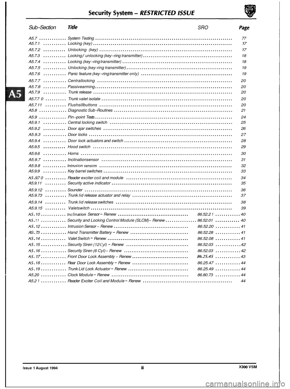
A5.7 ............. System Testing ...................................................................... 77
A5.7.1
........... Locking (key) ....................................................................... \
17
A5.7.2 ........... Unlocking (key) .................................................................... 17
A5.7.3 ........... Locking / unlocking (key-ring transmitter) ............................................... 18
A5.7.4
........... Locking (key-ring transmitter) ......................................................... 18
A5.7.5
........... Unlocking (key-ring transmitter) ....................................................... 19
A5.7.6
........... Panic feature (key-ring transmitter only) ................................................ 19
A5.7.7
........... Centrallocking ..................................................................... 20
A5.7.8
........... Passivearming ...................................................................... 20
A5.7.9
........... Trunk release ....................................................................... \
20
A5.7.7
0 .......... Trunk valet isolate ................................................................... 20
A5.7.11
.......... Flushsillbuttons .................................................................... 20
A5.9
............. Pin-point Tests ...................................................................... 24
A5.8
............. Diagnostic
Sub-Routines ............................................................. 21
A5.9.1
........... Central locking switch ............................................................... 25
A5.9.2
........... Door ajar switches .................................................................. 26
A5.9.3
........... Door locks ........................................................................\
. 27
A5.9.4
........... Door lock actuators and switch ........................................................ 28
A5.9.5
........... Hood switch ....................................................................... \
29 e
A5.9.6 ........... Horns ........................................................................\
..... 30
A5.9.7
........... Inclinationsensor ................................................................... 31
A5.9.8
........... Intrusionsensors .................................................................... 32
A5 . 9.7 0 .......... Reader exciter coil and module ....................................................... 34
A5.9.12
.......... Sounder ........................................................................\
... 36
A5.9.14
.......... Trunk lid release switches ............................................................ 38
A5.9.15
.......... Valetswitch ........................................................................\
39
A5 . 10 ............ Inclination Sensor - Renew ...................................... 86.52.2 1 ............ 40
A5 . 12 ............ Intrusion Sensor - Renew ........................................ 86.52.20 ............ 41
A5 . 14 ............ Valet Switch - Renew ........................................... 86.52.08 ............ 41
A5.9.9
........... Key
barrel switches .................................................................. 33
A5.9.11
.......... Security active indicator .............................................................. 35
A5.9.73
.......... Trunk lid release actuator and relay .................................................... 37
A5 . 11 ............ Security and Locking Control Module (SLCM) - Renew ............... 86.52.01 ............ 40
AS
. 73 ............ Hand Transmitter Battery - Renew ................................ 86.52.28 ............ 41
A5 . 15 ............ Security Siren (12 Cyl) - Renew .................................. 86.52.03 ............ 42
A5 . 16 ............ Security Siren (6 Cyl) - Renew ................................... 86.52.03 ............ 42
A5 . 17 ............ Front Door Lock Assembly - Renew ............................... 86.25.45 ............ 43
A5 . 18 ............ Rear Door Lock Assembly - Renew ............................... 86.25.47 ............ 44
Trunk Lid Lock Actuator - Renew ................................. 86.25.49 ............ 44
Clock Module - Renew ......................................... 86.80.73 ............ 44
Reader Exciter Coil and Module - Renew ............................................... 44
e
A5 . 19 ............
A5.20 ............
A5.2 1 ............
e
X300 VSM Issue 1 August 1994 ii
Page 478 of 521
0
c
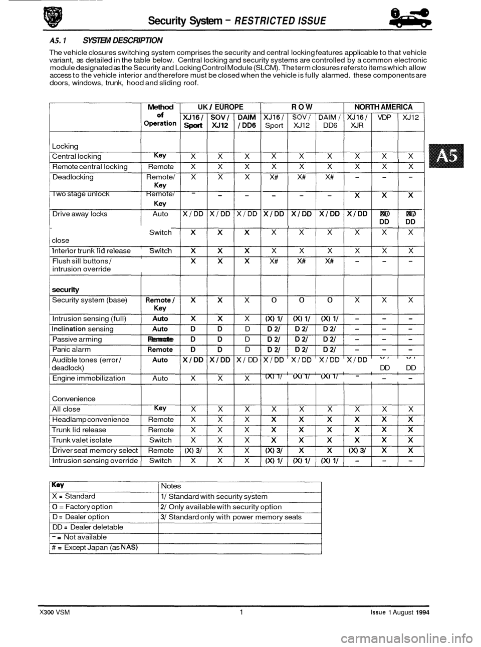
doors, windows, trunk, hood and sliding roof.
I Method I UK / EUROPE
of IXJ16I1SOVIIDAIM
Operation Sport XJ12 /DD6
Locking
Central locking Key X X X
Remote central locking Remote X X X
Deadlocking Remote/ X X X
Two stage unlock Remote/
- - - Key
Key
Drive away locks Auto X/DD X/DD X/DD
Switch
close
Interior trunk lid release Switch
Flush
sill buttons /
intrusion override
security
Security system (base)
Intrusion sensing (full)
Inclination sensing
Passive arming
Panic alarm
Audible tones (error
/
deadlock)
Engine immobilization
*
Auto
.,,,
Remote
Auto
1 XI X X
X D
D D
X/ DD
X
-~~
Security System - RESTRICTED ISSUE
AS. 1 SYSTEM DESCRIPTION
The vehicle closures switching system comprises the security and central locking features applicable to that vehicle
variant, as detailed in the table below. Central locking and security systems are controlled by a common electronic
module designated as the Security and Locking Control Module (SLCM). The term closures refersto items which allow
access to the vehicle interior and therefore must be closed when the vehicle is fully alarmed. these components are
Convenience
All close Key X X X
Headlamp convenience Remote X X X
Trunk lid release Remote X X X
Trunk valet isolate Switch X X X
Driver seat memory select Remote
(X) 3/ X X
Intrusion sensing override Switch X X X
ROW NORTH AMERICA
XJ16/ SOV/ DAlM/ XJ16/ VDP XJ12
Sport XJ12 DD6 XJR
X X X X X X
I X X X X X X
X# X# X# - - -
$$$$$ DD DD
I I I I I X X X X X X
X X X X X X
X# X# X# - - -
I 0 0 0 X X X
X/DD X/DD X/DD X/DD
DD DD
(X) 1/ (XI 1/ (XI 1/ - - -
X X X X X X
Key Notes
X = Standard
0 = Factory option
D
= Dealer option
DD
= Dealer deletable
1/ Standard with security system
2/ Only available with security option
3/ Standard only with power memory seats
- = Not available
# = Except Japan (as NAS)
X300 VSM 1 Issue 1 August 1994
Page 480 of 521
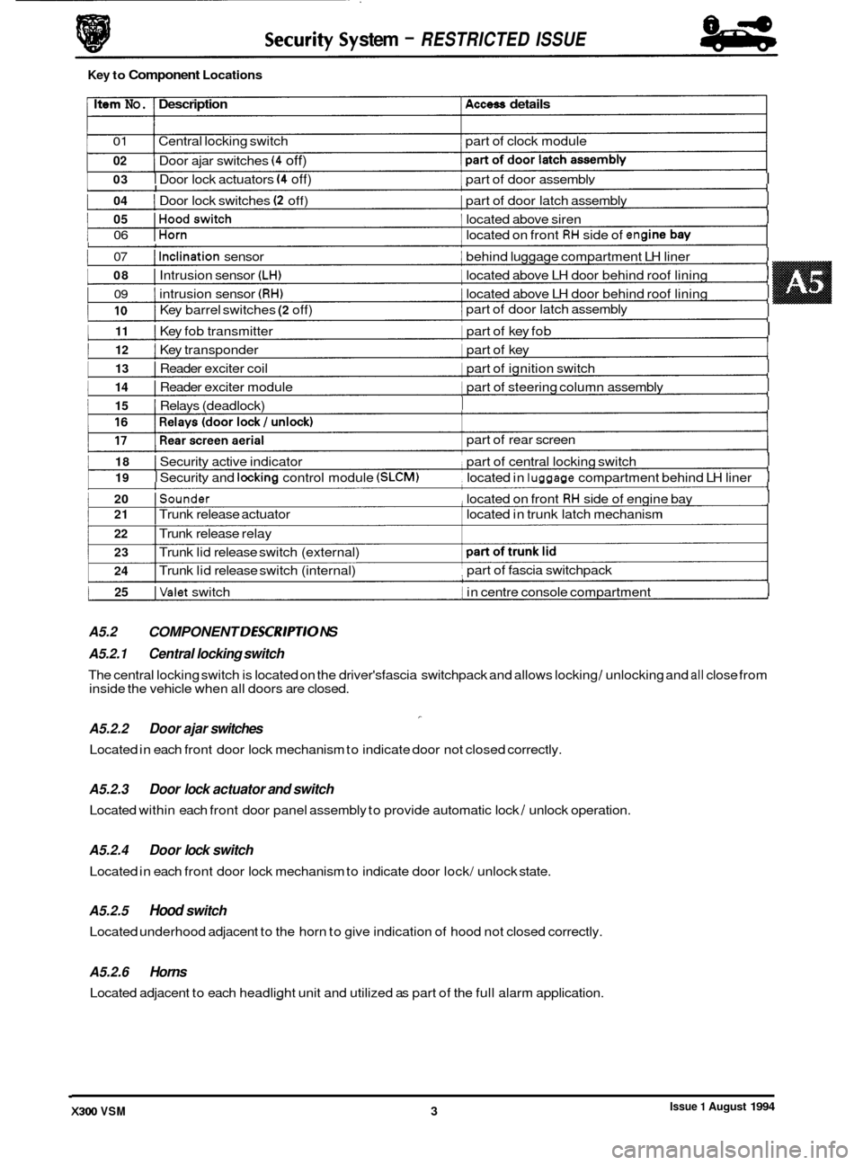
I 03 I Door lock actuators (4 off) 1 part of door assemblv I I
Issue 1 August 1994 X300 VSM 3 I
1 04 I Door lock switches (2 off) I part of door latch assembly I I
1 05 IHoodswitch 1 located above siren I I
1 06 IHorn 1 located on front RH side of en(
1 07 I Inclination sensor I behind luggage compartment LH liner I I
I 08 I Intrusion sensor (LH) I located above LH door behind roof lining I
I 09 I intrusion sensor (RH) 1 located above LH door behind roof lining I
I
1 1 part of door latch assembly I 10 I Key barrel switches (2 off)
1 11 I Key fob transmitter 1 part of key fob I I
I 12 I Key transponder 1 part of key I I
I 13 I Reader exciter coil 1 part of ignition switch I I
I 14 I Reader exciter module 1 part of steering column assembly I I
1 15 I Relays (deadlock) I I I
1 18 I Security active indicator part of central locking switch I I
I 19 I Securitv and lockina control module (SLCM) located in luaaaae compartment behind LH liner I I
1 20 ISounder , located on front RH side of engine bay I I
1 25 IValet switch 1 in centre console compartment I I
A5.2 COMPONENT DESCR/PT/O NS I
stem - RESTRICTED ISSUE
Key to Component Locations
Item No. Description Access details
01 Central locking switch part of clock module
02
1 I
Door ajar switches (4 off)
I I
part of rear screen
I 21 I Trunk release actuator located in trunk latch mechanism
22 I Trunk release relay
23
24 I Trunk lid release switch (external)
I Trunk lid release switch (internal) part of
fascia switchpack ,
A5.2.1 Central locking switch
A5.2.2 Door ajar switches
Located in each front door lock mechanism to indicate door not closed correctly.
-
The central locking switch is located on the driver'sfascia switchpack and allows locking / unlocking and all close from
inside the vehicle when all doors are closed.
A5.2.3
Located within each front door panel assembly to provide automatic lock / unlock operation.
Door lock actuator and switch
A5.2.4 Door lock switch
Located in each front door lock mechanism to indicate door lock/ unlock state.
A5.2.5 Hood switch
Located underhood adjacent to the horn to give indication of hood not closed correctly.
A5.2.6 Horns
Located adjacent to each headlight unit and utilized as part of the full alarm application.
Page 481 of 521
84
- Security System - RESTRICTED /SSU€
A5.2.7 Inclination sensor
Located adjacent to the SLCM underthe luggage compartment LH side linerto give indication of unauthorized jacking / lifting of the vehicle.
A5.2.8 Intrusion sensors
Located above each front door to give indication of unauthorized entry into the vehicle passenger compartment.
A5.2.9 Reader exciter coil
Forms an integral part of the ignition switch to prove correct key insertion by communicating key transponder signal
to control module.
A5.2.10 Reader exciter module
Located on the steering column to receive signals from the reader/ exciter coil and disarm the engine immobilization
system on correct demand.
A5.2.11 Security active indicator
An LED built into the central locking switch to indicate when security system is armed.
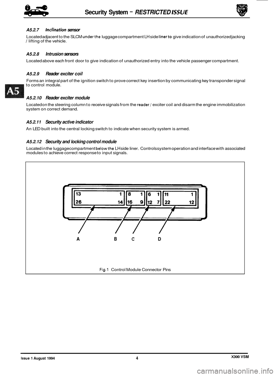
A5.2.12 Security and locking control module
Located in the luggage compartment belowthe LH side liner. Controls system operation and interface with associated
modules to achieve correct response to input signals.
L
Fig.1 Control Module Connector Pins
/ // /
A B C D
X300 VSM Issue 1 August 1994 4
Page 482 of 521
Security System
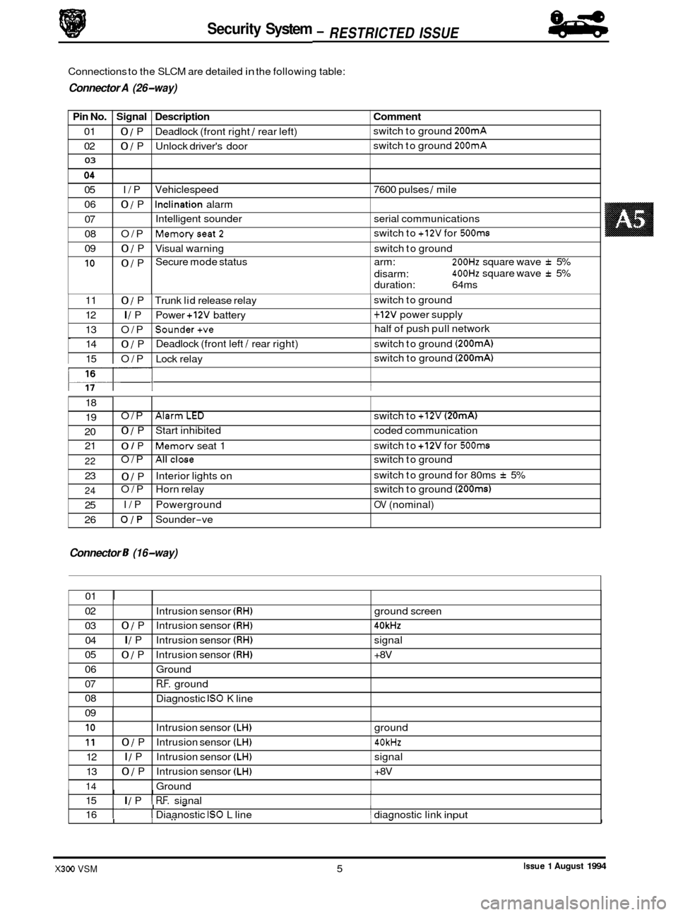
Pin No. Signal Description
01 0 / P Deadlock (front right / rear left)
02
0 / P Unlock driver's door
03
Connections to the SLCM are detailed in the following table:
9 Connector A (26-way)
Comment
switch to ground 200mA
switch to ground 200mA
05 I/P
06
0 / P
07
08 O/P
09
0 / P
10 0 / P Vehiclespeed
7600 pulses
/ mile
Inclination alarm
Intelligent sounder serial communications
Memoryseat2
Visual warning switch to ground
Secure mode status arm:
200Hz square wave f 5%
400Hz square wave f 5%
switch
to
+12V for 500ms
disarm:
duration: 64ms
0
117- I I
11 0 / P Trunk lid release relay 1 switch to ground
12
I / P Power +12V battery 1 + 12V power supply
13 O/P
Sounder+ve half of push pull network
14
0 / P Deadlock
(front left / rear right) switch to ground (200mA)
15 O/P Lock relay switch
to ground (200mA)
18
19
20 21 O/P
AlarmLED switch
to +12V (20mA)
0 / P Start inhibited coded communication
0 / P Memorv seat 1 switch
to +12V for 500ms
Connector 8 (16-way)
22
23
24
25
26 O/P
Allclose switch
to ground
0 / P
O/P Horn relay switch to ground
(200ms)
I/P Powerground OV (nominal)
OJP Sounder-ve
Interior lights
on switch
to ground for 80ms
f 5%
01
I
02
03 04
05
06
07
08
09
I I I I 15 I I / P I R.F. sianal
Intrusion
sensor
(RH) ground screen
0 / P Intrusion sensor (RH) 40kHz
I / P Intrusion sensor (RH) signal
0 / P Intrusion sensor (RH) +8V
Ground
R.F. ground
Diagnostic
IS0 K line
I. I - I 16 I I Diaanostic IS0 L line 1 diagnostic link input
10
11
12
13
14
.I
I I" 1- I
Intrusion sensor (LH) ground
0 / P Intrusion sensor (LH) 40kHz
I / P Intrusion sensor (LH) signal
0 / P Intrusion sensor (LH) +8V
Ground
Issue 1 August 1994 X300 VSM 5
84
- RESTRICTED ISSUE -