sensor JAGUAR XJ6 1994 2.G Owner's Manual
[x] Cancel search | Manufacturer: JAGUAR, Model Year: 1994, Model line: XJ6, Model: JAGUAR XJ6 1994 2.GPages: 521, PDF Size: 17.35 MB
Page 103 of 521
Exhaust System (AJ16)
9
/ 7 I
3;
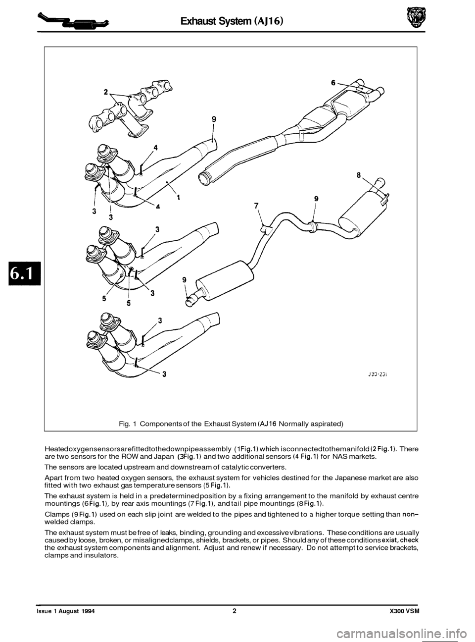
Fig. 1 Components of the Exhaust System (AJ16 Normally aspirated)
J?3-Z2l
Heated oxygensensorsarefittedtothedownpipeassembly (1 Fig.l)which isconnectedtothemanifold (2 Fig.1). There
are two sensors for the ROW and Japan (3 Fig.1) and two additional sensors (4 Fig.1) for NAS markets.
The sensors are located upstream and downstream of catalytic converters.
Apart from two heated oxygen sensors, the exhaust system for vehicles destined for the Japanese market are also
fitted with two exhaust gas temperature sensors
(5 Fig.1).
The exhaust system is held in a predetermined position by a fixing arrangement to the manifold by exhaust centre
mountings (6 Fig.l), by rear axis mountings (7 Fig.l), and tail pipe mountings (8 Fig.1).
Clamps (9 Fig.1) used on each slip joint are welded to the pipes and tightened to a higher torque setting than non- welded clamps.
The exhaust system must be free of leaks, binding, grounding and excessive vibrations. These conditions are usually
caused by loose, broken, or misaligned clamps, shields, brackets, or pipes. Should any of these conditions
exist,check the exhaust system components and alignment. Adjust and renew if necessary. Do not attempt to service brackets,
clamps and insulators.
Issue 1 August 1994 2 X300 VSM
Page 110 of 521
Exhaust System (V12)
6.2.1 GENERAL DESCRIPTION
6
4 5
J30-234
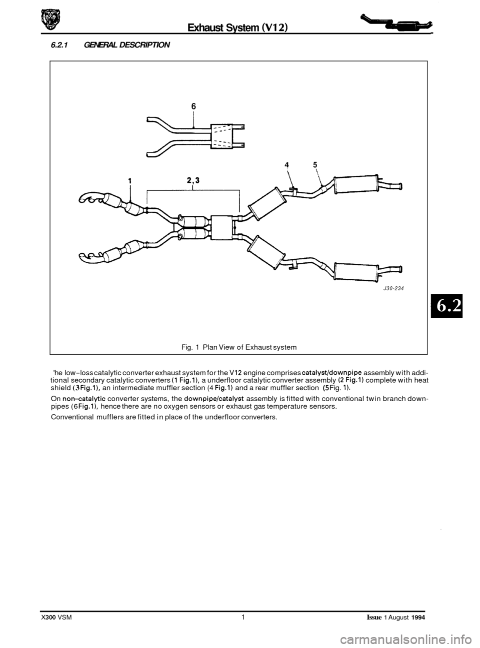
Fig. 1 Plan View of Exhaust system
'he low
-loss catalytic converter exhaust system for the VI2 engine comprises catalyst/downpipe assembly with addi- tional secondary catalytic converters (1 Fig.11, a underfloor catalytic converter assembly (2 Fig.1) complete with heat
shield (3 Fig.l), an intermediate muffler section (4 Fig.1) and a rear muffler section (5 Fig. 1).
On non-catalytic converter systems, the downpipe/catalyst assembly is fitted with conventional twin branch down- pipes (6 Fig.11, hence there are no oxygen sensors or exhaust gas temperature sensors.
Conventional mufflers are fitted in place of the underfloor converters.
X300 VSM 1 Issue 1 August 1994
Page 111 of 521
b Exhaust System (V12)
8
Fig.
P
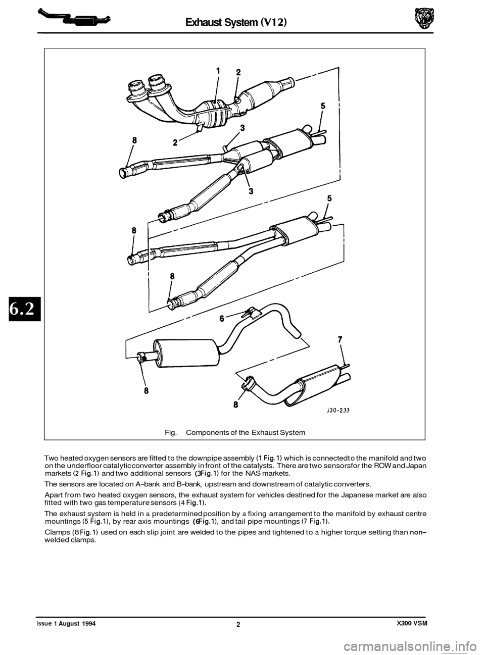
Components of the Exhaust System
130 -2 33
Two heated oxygen sensors are fitted to the downpipe assembly (1 Fig.1) which is connected to the manifold and two
on the underfloor catalytic converter assembly in front of the catalysts. There are two sensorsfor the ROW and Japan
markets (2 Fig.1) and two additional sensors (3 Fig.1) for the NAS markets.
The sensors are located on A
-bank and B-bank, upstream and downstream of catalytic converters.
Apart from two heated oxygen sensors, the exhaust system for vehicles destined for the Japanese market are also
fitted with two gas temperature sensors
(4 Fig.1).
The exhaust system is held in a predetermined position by a fixing arrangement to the manifold by exhaust centre
mountings (5 Fig.l), by rear axis mountings (6 Fig.1). and tail pipe mountings (7 Fig.1).
Clamps (8 Fig.1) used on each slip joint are welded to the pipes and tightened to a higher torque setting than non- welded clamps. ~ ~~~
Issue 1 August 1994 2 X300 VSM
Page 119 of 521
Manual Transmission & Clutch (AJ16)
7.1.2 MANUAL TRANSMISSION ASSEMBLY, RENEW
SRO 37.20.01
. Disconnect the battery.
. Remove inlet manifold rear securing nuts.
. Remove injector harness mounting bracket.
. Fit lifting bracket 18G 1465 and secure with the nuts.
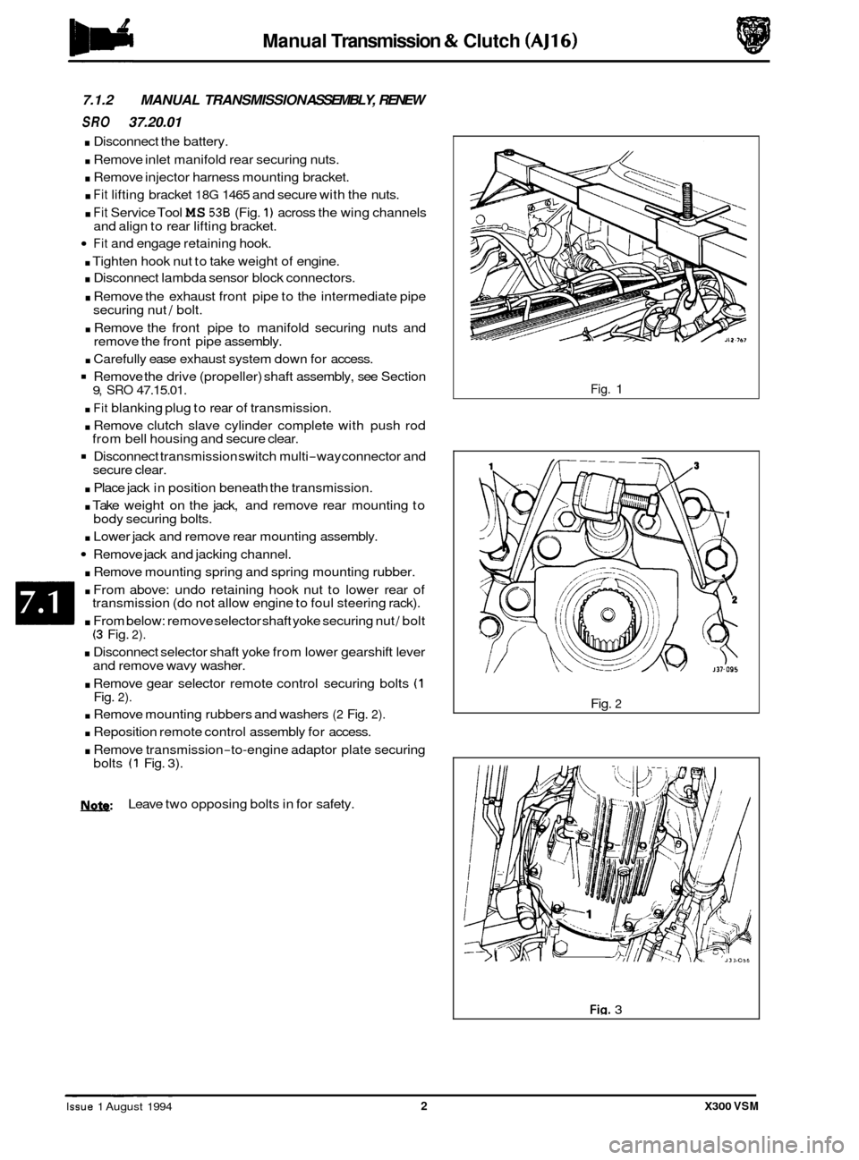
. Fit Service Tool MS 536 (Fig. 1) across the wing channels
Fit and engage retaining hook.
. Tighten hook nut to take weight of engine.
. Disconnect lambda sensor block connectors.
. Remove the exhaust front pipe to the intermediate pipe
securing nut / bolt.
. Remove the front pipe to manifold securing nuts and
remove the front pipe assembly.
. Carefully ease exhaust system down for access.
Remove the drive (propeller) shaft assembly, see Section
. Fit blanking plug to rear of transmission.
. Remove clutch slave cylinder complete with push rod
Disconnect transmission switch multi-way connector and
. Place jack in position beneath the transmission.
. Take weight on the jack, and remove rear mounting to
. Lower jack and remove rear mounting assembly.
Remove jack and jacking channel.
. Remove mounting spring and spring mounting rubber.
. From above: undo retaining hook nut to lower rear of
transmission (do not allow engine to foul steering rack).
. From below: remove selector shaft yoke securing nut / bolt (3 Fig. 2).
. Disconnect selector shaft yoke from lower gearshift lever
and remove wavy washer.
. Remove gear selector remote control securing bolts (1 Fig. 2).
. Remove mounting rubbers and washers (2 Fig. 2).
. Reposition remote control assembly for access.
. Remove transmission-to-engine adaptor plate securing
and
align to rear lifting bracket.
9, SRO 47.15.01.
from bell housing and secure clear.
secure clear.
body securing bolts.
bolts
(1 Fig. 3).
N.&: Leave two opposing bolts in for safety.
Fig. 1
Fig.
2
Fig. 3 ~ ~ ~~ ~
Issue 1 August 1994 2 X300 VSM
Page 124 of 521
Manual Transmission & Clutch (AJ16)
GEARSHIFT LEVER KNOB, RENEW
:RY 37.16.11
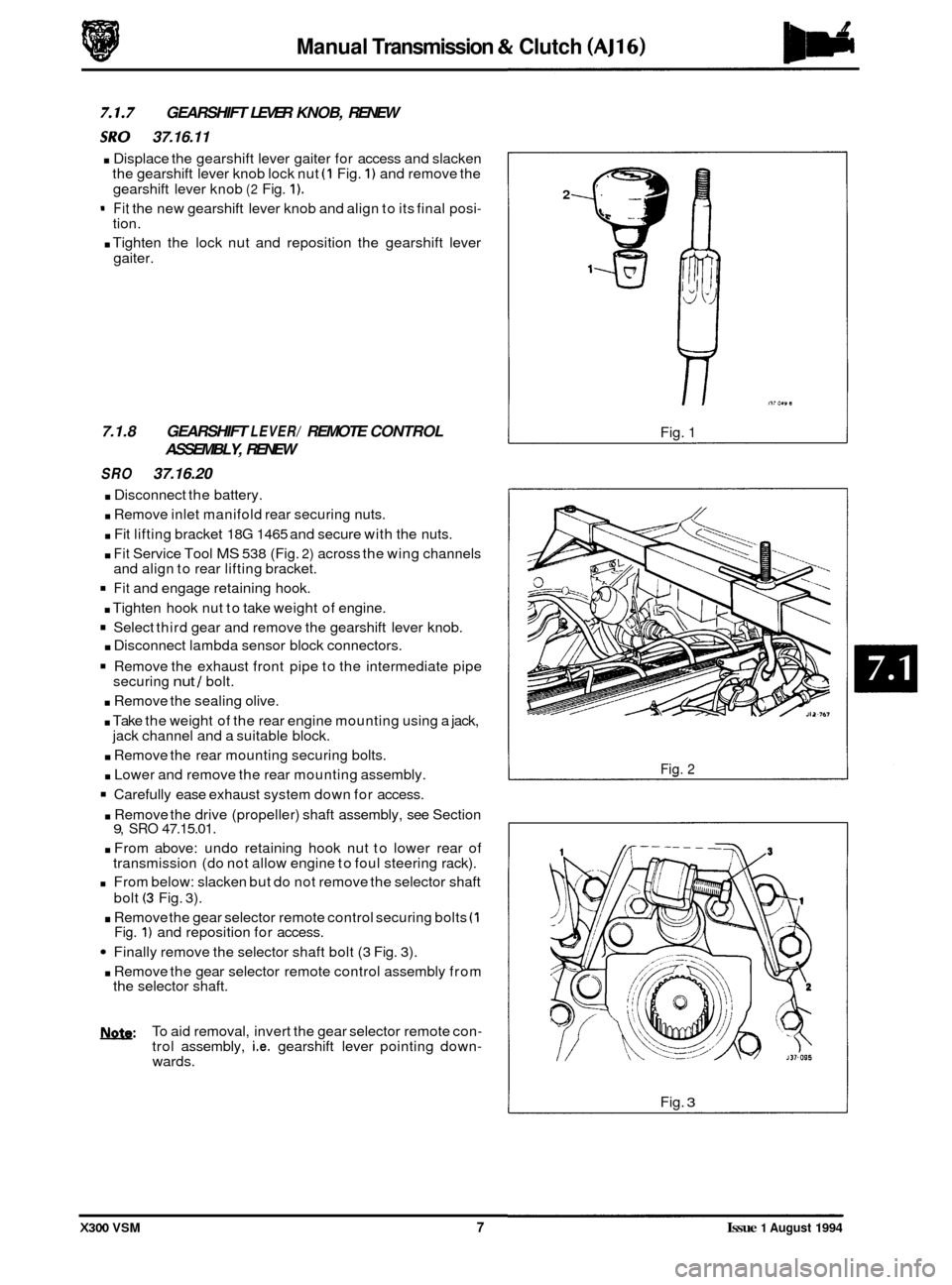
. Displace the gearshift lever gaiter for access and slacken
the gearshift lever knob lock nut (1 Fig. 1) and remove the
gearshift lever knob
(2 Fig. 1).
- Fit the new gearshift lever knob and align to its final posi- tion.
. Tighten the lock nut and reposition the gearshift lever
gaiter.
7.1.8 GEARSHIFT LEVER/ REMOTE CONTROL
ASSEMBLY, RENEW
SRO 37.16.20
. Disconnect the battery.
. Remove inlet manifold rear securing nuts.
. Fit lifting bracket 18G 1465 and secure with the nuts.
. Fit Service Tool MS 538 (Fig. 2) across the wing channels
and align to rear lifting bracket.
Fit and engage retaining hook.
. Tighten hook nut to take weight of engine.
Select third gear and remove the gearshift lever knob.
. Disconnect lambda sensor block connectors.
Remove the exhaust front pipe to the intermediate pipe
securing nut / bolt.
. Remove the sealing olive.
. Take the weight of the rear engine mounting using a jack,
. Remove the rear mounting securing bolts.
. Lower and remove the rear mounting assembly.
Carefully ease exhaust system down for access.
jack channel
and a suitable block.
. Remove the drive (propeller) shaft assembly, see Section 9, SRO 47.15.01.
. From above: undo retaining hook nut to lower rear of
transmission (do not allow engine to foul steering rack).
From below: slacken but do not remove the selector shaft
bolt
(3 Fig. 3).
. Remove the gear selector remote control securing bolts (1 Fig. 1) and reposition for access.
Finally remove the selector shaft bolt (3 Fig. 3).
. Remove the gear selector remote control assembly from
the selector shaft.
b: To aid removal, invert the gear selector remote con- trol assembly, i.e. gearshift lever pointing down- wards.
2
Fig. 1
Fig. 2
Fig. 3
X300 VSM 7 Issue 1 August 1994
Page 136 of 521

Automatic Transmission (AJ16)
SECTION CONTENTS
Subsection Title SRO Page
I to IV ............ Preliminary Pages .................................................................... i
8.1.1 ............. General Description .................................................................. 1
8.1.2 ............. Transmission Fluid. Renew (3. 2L and 4. OL) ......................... 44.24.02 ............. 6
8.1.3 ............. Transmission Control Module. Renew (4. OL) ........................ 44.15.32 ............. 7
8.1.4 ............. Transmission Rotary Switch. Adjust (4. OL) .......................... 44.15.37 ............. 8
8.1.5
............. Transmission Rotary Switch. Renew (4.0L) .......................... 44.15.36 ............. 9
8.1.6 ............. Transmission Fluid Filter, Renew (3. 2L and 4. OL)
8.1.7 ............. Fluid Pan. Renew (4. OL) ......................................... 44.24.04 ............
8.1.8 ............. Fluid Pan. Renew (3. 2L) ......................................... 44.24.04 ............ 12
8.1.9
............. Fluid Pan Gasket. Renew (3. 2L) .................................. 44.24.05 ............ 12
8.1.10.
........... Transmission Speed Sensor, Renew (4. OL) .......................... 44.15.34 ............ 13
8.1.1 1 ............ Transmission Internal Harness Multi-pin Socket '0' ring. Renew (4. OL) . 4424.20 ............ 14
Valve Body Assembly, Renew (4. OL) ............................... 44.40.01 ............ 15
.................... 44.24.07 ............ 11
11
8.1.12 ............
8.1.13 ............ Valve Body Assembly, Renew (3.2L) ............................... 44.40.01 ............ 16
X300 VSM i Issue 1 August 1994
Page 150 of 521
Automatic Transmission (AJ16)
8.1.10 TRANSMISSION SPEED SENSOR, RENEW (4,OL)
SRO 44.15.34
9 Raise the hood and fit a fender cover.
. Raise the vehicle on a ramp.
. Drain the transmission lubrication system, see Sub-sec-
Remove the fluid pan, see Sub-section 8.1.7.
. Displace the transmission speed sensor harness from the
valve body rear securing clip.
Release and remove the speed sensor and connector re-
taining clip from the valve body.
. Displace the speed sensor and connector from the trans-
mission main casing.
9 Disconnect and remove the speed sensor from the har-
ness connector.
. Clean the speed sensor, retaining clip and mating surface.
Connect the new speed sensor to the harness connector.
Fully seat the speed sensor into the transmission unit
tion
8.1.2.
main
casing.
. Fit the speed sensor and connector retaining clip to the
valve body, engaging the tangs onto the connector.
clip securing screws.
the valve body rear; secure the clip.
. Fit and tighten the speed sensor and connector retaining
. Reposition and fully seat the speed sensor harness into
. Refit the fluid pan, see Sub-section 8.1.7.
. Lower the vehicle on the ramp.
. Refill the transmission unit with fluid, see Sub-section
8.1.2.
Remove the fender cover and lower the hood.
X300 VSM 13 Issue 1 August 1994
Page 151 of 521
Automatic Transmission (AJ16)
8.1.11 TRANSMISSION INTERNAL HARNESSMULTI-
PIN SOCKET '0' RING, RENEW (4,OL)
SRO 44.24.20
. Disconnect the battery.
. Raise the vehicle on a ramp.
. Drain the transmission lubrication system, see Sub-sec-
. Remove the fluid pan, see Sub-section 8.1.7.
. Remove the fluid filter, see Sub-section 8.1.6.
. Remove the transmission speed sensor, see Sub-section
8.1.10.
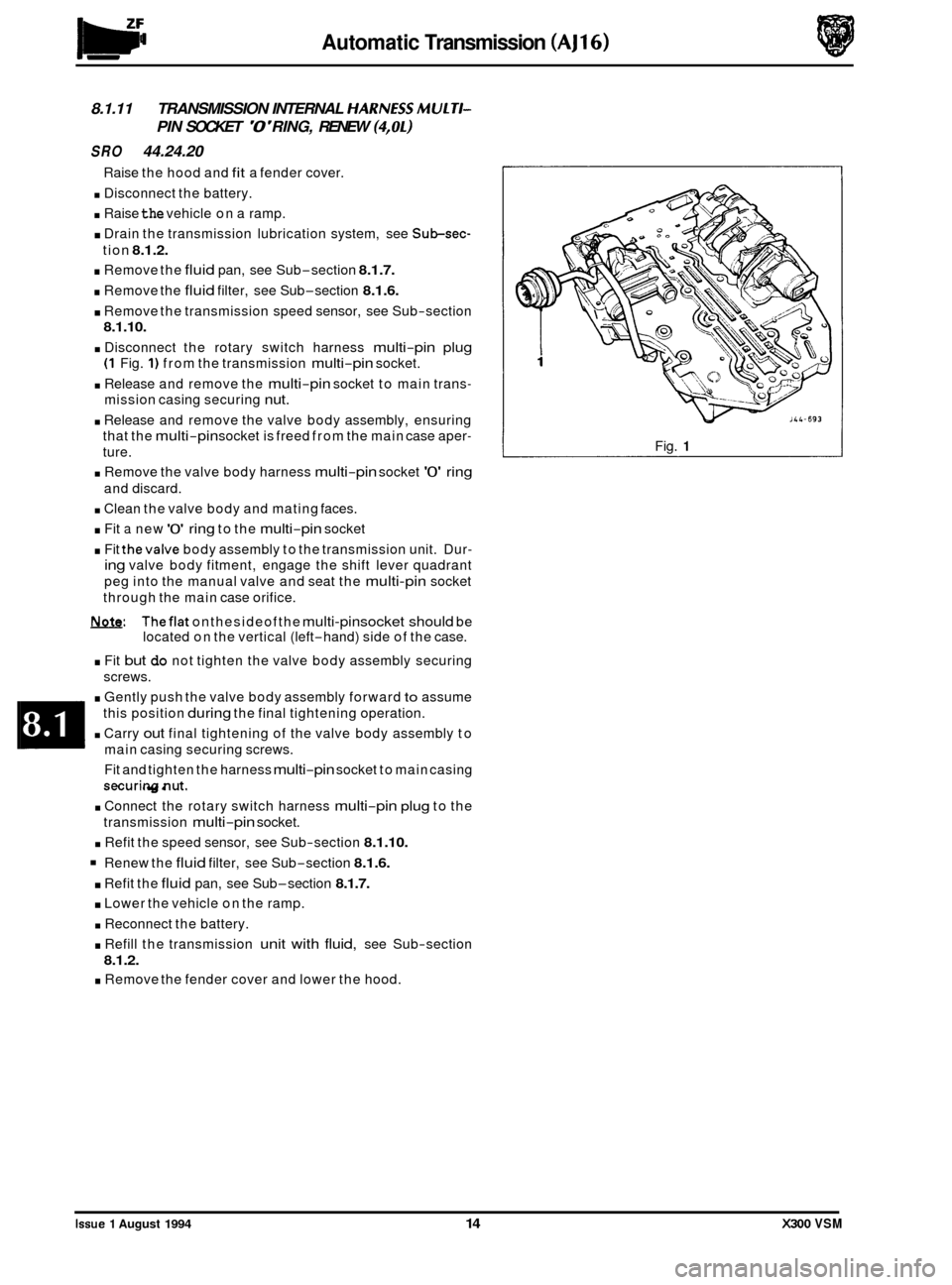
. Disconnect the rotary switch harness multi-pin plug
(1 Fig. 1) from the transmission multi-pin socket.
. Release and remove the multi-pin socket to main trans-
mission casing securing nut.
. Release and remove the valve body assembly, ensuring
that the
multi-pin socket is freed from the main case aper-
ture.
. Remove the valve body harness multi-pin socket '0' ring
and discard.
. Clean the valve body and mating faces.
. Fit a new '0' ring to the multi-pin socket
. Fit thevalve body assembly to the transmission unit. Dur-
ing valve body fitment, engage the shift lever quadrant
peg into the manual valve and seat the
multi-pin socket
through the main case orifice.
m. Theflat onthesideofthe multi-pinsocket should be
located on the vertical (left-hand) side of the case.
. Fit but do not tighten the valve body assembly securing
screws.
. Gently push the valve body assembly forward to assume
this position
during the final tightening operation.
. Carry out final tightening of the valve body assembly to
main casing securing screws.
Fit and tighten the harness
multi-pin socket to main casing
securingnut.
. Connect the rotary switch harness multi-pin plug to the
transmission
multi-pin socket.
. Refit the speed sensor, see Sub-section 8.1.10.
Renew the fluid filter, see Sub-section 8.1.6.
. Refit the fluid pan, see Sub-section 8.1.7.
. Lower the vehicle on the ramp.
. Reconnect the battery.
. Refill the transmission unit with fluid, see Sub-section
8.1.2.
. Remove the fender cover and lower the hood.
Raise
the hood and
fit a fender cover.
tion
8.1.2.
Fig. 1
Issue 1 August 1994 14 X300 VSM
Page 152 of 521
Automatic Transmission (AJ16)
8.1.12 VALVE BODY ASSEMBLY, RENEW (4,Ol)
SRO 44.40.01
Raise the hood and fit a fender cover.
. Disconnect the battery.
. Raise the vehicle on a ramp.
. Drain the transmission lubrication system, see Sub-sec-
. Remove the fluid pan, see Subsection 8.1.7.
. Remove the fluid filter, see Sub-section 8.1.6.
. Remove the transmission speed sensor, see Subsection
8.1.10.
. Disconnect the rotary switch harness multi-pin plug from
the transmission multi
-pin socket.
. Release and remove the multi-pin socket to main trans-
mission casing securing nut.
Release and remove the valve body assembly to main cas-
ing securing screws.
. DisDlace and remove the valve body assemblv, ensurina
tion
8.1.2.
that
the multi-pin socket is freed from the main case apery
ture. - . Remove the valve body harness multi-pin socket '0' ring
. Clean the valve body and main case mating faces. Check
. Fit a new '0' ring to the multi-pin socket.
. Fit the valve body assembly to the transmission unit. Dur-
ing valve body fitment, engage the shift lever quadrant
peg into the manual valve and seat the multi
-pin socket
through the main case orifice.
m: Theflat on the side of the multi-pin socket should be
located on the vertical (left-hand) side of the case.
. Fit but do not tighten the valve body assembly securing
screws.
Gently push the valve body assembly forward to assume
this position during the final tightening operation.
Carry out final tightening of the valve body assembly to
main casing securing screws.
. Fit and tighten the harness multi-pin socket to main casing
. Connect the rotary switch harness multi-pin plug to the
. Refit the speed sensor, see Subsection 8.1.10.
. Renew the fluid filter, see Subsection 8.1.6.
Refit the fluid pan, see Sub-section 8.1.7.
* Lower the vehicle on the ramp.
. Reconnect the battery.
. Refill the transmission unit with fluid, see Sub-section
8.1.2.
. Remove the fender cover and lower the hood.
and discard.
for any signs of damage.
securing nut.
transmission multi
-pin socket.
Issue 1 August 1994 X300 VSM 15
Page 154 of 521

Ponnrtrain Automatic Transmission (V12 & AJ16 Supercharged)
SECTION CONTENTS
Sub-Section Title SRO Page
It0 IV ............ Preliminary Pages .................................................................... i
8.2.1 ............. General Description .................................................................. 1
8.2.2 ............. Transmission internal Harness. Renew (4. OL SC and 6. OL) ............ 44.15.35 ............. 5
8.2.3 ............. Pressure Switch Manifold. Renew (4. OL SC and 6. OL) ................ 44.15.39 ............. 6
8.2.4 ............. Input Speed Sensor, Renew (4. OL SC) .............................. 44.15.40 ............. 7
8.2.5 ............. OutputSpeedSensor, Renew(4. OL SC) ............................ 44.75.41 ............. 7
8.2.6 ............. input Speed Sensor, Renew (6. OL} ................................. 44.15.40 ............. 8
8.2.7
............. Output Speed Sensor, Renew (6. OL) ............................... 44.15.41 ............. 9
8.2.8.
............ Temperature Sensor, Renew (4. OL SC and 6. OL) .......................................... 10
8.2.9
............. Variable Force Motor, Renew(4. 0L SC and 6.OL) ..................... 44.15.43 ............ 70
8.2.10. ........... Pulse Width Modulator (TCC Solenoid). Renew (4. OL SC and 6. OL) ..... 44.15.44 ............ 11
8.2.17 ............ 'A' Shift Solenoid. Renew (4. OL SC and 6. OL) ....................... 44.15.45 ............ 12
8.2.12.
........... '6' Shift Solenoid. Renew (4. OL SC and 6. OL) ....................... 44.15.46 ............ 13
8.2.13
............ Lubrication System. Drain and Refill (4. OL SCand 6. OL) .............. 44.24.02 ............ 14
8.2.14
............ Fluid Pan. Renew (4. OL SC} ...................................... 44.24.04 ............ 15
8.2.15 ............ Fluid Pan. Renew (6. OL) ......................................... 44.24.04 ............ 16
8.2.16.
............ Fluid Pan Gasket. Renew (4. OL SC) ................................ 44.24.05 ............ 17
8.2.17. ........... Fluid Pan Gasket. Renew (6. OL) .................................. 44.24.05 ............ 78
8.2.18. ........... Fluid Filter, Renew (4. OL SC and 6. OL) ............................. 44.24.07 ............ 19
8.2.19 ............ Transmission Internal Harness Multi-pin Socket '0' Ring.
Renew (4.
OL SC and 6. OL) ....................................... 44.24.20 ............ 20
8.2.20
............ Internal Lubrication Pipe. Renew (4. OL SC and 6. OL) ................ 44.24.21 ............ 21
8.2.21
............ internal Dipstick Stop. Renew (4. OL SC and 6. OL) ................... 44.24.22 ............ 22
8.2.22.
........... Manual Detent Spring. Renew (4. OL SC and 6. OL) ................... 44.26.10 ............ 23
X300 VSM i Issue 1 August 1994