torque JAGUAR XJ6 1994 2.G Repair Manual
[x] Cancel search | Manufacturer: JAGUAR, Model Year: 1994, Model line: XJ6, Model: JAGUAR XJ6 1994 2.GPages: 521, PDF Size: 17.35 MB
Page 315 of 521

Climate Control Systems
0 Because HFC 134A is fully recycleable it may be 'cleaned' by the recovery equipment and re-used following
removal from a system.
0 Leak tests should only be carried out with an electronic analyzer which is dedicated to HFC 134A. Never use a CFC 12 analyzer or naked flame type.
0 Do not attempt to 'guess' the amount of refrigerant in a system, always recover and recharge with the correct
charge weight. In this context do not depress the charge or discharge port valves to check for the presence of
refrigerant.
14.1.3 Handling Lubricating Oil
0 Avoid breathing lubricant mist, it may cause irritation to your respiratory system.
0 Always decant fresh oil from a sealed container and do not leave oil exposed to the atmosphere for any reason
other than to fill or empty a system. PAG oil is very hygroscopic (absorbs water) and will rapidly become con-
taminated by atmospheric moisture.
PAG oil is
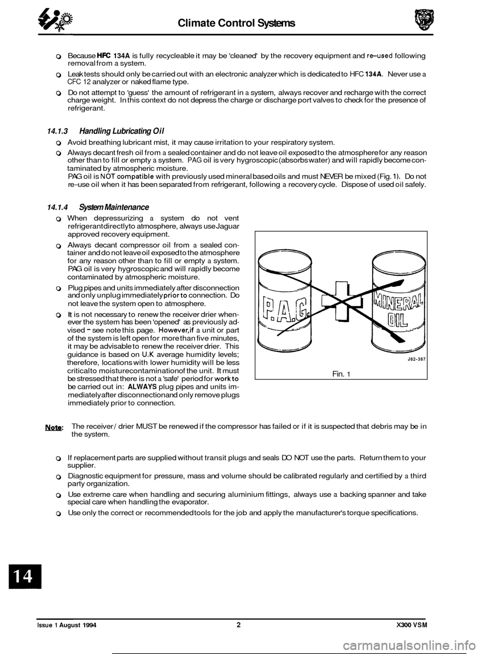
NOTcompatible with previously used mineral based oils and must NEVER be mixed (Fig. 1). Do not
re
-use oil when it has been separated from refrigerant, following a recovery cycle. Dispose of used oil safely.
14.1.4 System Maintenance
0 When depressurizing a system do not vent
refrigerant directlyto atmosphere, always use Jaguar
approved recovery equipment.
0 Always decant compressor oil from a sealed con- tainer and do not leave oil exposed to the atmosphere
for any reason other than to fill or empty
a system.
PAG oil is very hygroscopic and will rapidly become
contaminated by atmospheric moisture.
0 Plug pipes and units immediately after disconnection
and only unplug immediately priorto connection. Do
not leave the system open to atmosphere.
0 It is not necessary to renew the receiver drier when- ever the system has been 'opened' as previously ad-
vised - see note this page. However,if a unit or part
of the system is left open for more than five minutes,
it may be advisable to renew the receiver drier. This
guidance is based on
U.K average humidity levels;
therefore, locations with lower humidity will be less
critical to moisturecontamination of the unit.
It must
be stressed that there is not
a 'safe' period for workto
be carried out in: ALWAYS plug pipes and units im-
mediately after disconnection and only remove plugs
immediately prior to connection.
J82-387
Fin. 1
U: The receiver / drier MUST be renewed if the compressor has failed or if it is suspected that debris may be in
the system.
0 If replacement parts are supplied without transit plugs and seals DO NOT use the parts. Return them to your
supplier.
0 Diagnostic equipment for pressure, mass and volume should be calibrated regularly and certified by a third
party organization.
0 Use extreme care when handling and securing aluminium fittings, always use a backing spanner and take
special care when handling the evaporator.
0 Use only the correct or recommended tools for the job and apply the manufacturer's torque specifications.
Issue 1 August 1994 2 X300 VSM
Page 326 of 521

Climate Control Systems
0 14.9 GENERAL SYSTEM PROCEDURES
14.9.1 Leak Test
Faults associated with low refrigerant charge weight and low pressure may be caused by leakage. Leaks traced to
mechanical connections may be caused by torque relaxation or joint face contamination. Evidence of oil around such
areas is an indicator of leakage. When checking for non visible leaks use only
a dedicated HFC 134A electronic analyzer
and apply the probe all round the joint / connection.
Should a leak betraced to a joint,checkthatthefixing issecuredtothecorrecttightening torque before any other action
is taken.
Do not forget to check the compressor shaft seal and evaporator.
CAUTION : Never use a dedicated CFC 12 or naked flame type analyzer.
14.9.2 Charge Recovery (System depressurization)
The process of HFC 134A recovery will depend on the basic characteristics of your chosen recovery/ recycle I recharge
equipment, therefore, follow the manufacturer's instructions carefully.
Remember that compressor oil may be drawn
out of the system by this process, take note of the quantity recovered
so that it may be replaced.
CAUTION: Observe all relevant safety requirements.
Wear suitable eye and skin protection
Do not mix HFC 134A with CFC 12. Do not vent refrigerant directly to atmosphere and always use Jaguar approved recovery I recycle I re- charge equipment.
Take note of the amount of recovered refrigerant, it will indicate the state of the system. 0
14.9.3 Evacuating the System
This process, the removal of unwanted air and moisture, is critical to the correct operation of the air conditioning sys-
tem. The specific procedures will vary depending on the individual characteristics of your chosen recovery I recycle / recharge equipment and must be carried out exactly in accordance with the manufacturers instructions. However,
it is recommended that the initially only the HIGH side valve be opened at the start of the procedure. After a short time a small depression should be seen on the LOW side, at which point the LOW side valve may be opened and the evacu- ation process completed. If a vacuum is not registered on the LOW side it may indicate that the expansion valve is
jammed closed or that the system is blocked. This simple check may save time and effort when the system is re- charged.
Moisture can be highly destructive and may cause internal blockages due to freezing, but more importantly, water sus- pended in the PAG oil will damage the compressor. Once the system has been opened for repairs, or the refrigerant
charge recovered, all traces of moisture MUST be removed before recharging.
14.9.4
The amount of oil drawn out during a recovery procedure will be dependent on the state of the system and the rate
of recovery. The quantity will be approximately 30 to 40 ml; this may vary, and the figure is given only for guidance.
The oil separator vessel in the recovery equipment must be clean and empty
at the start of the process so that the quan- tity of oil which is drawn out may be accurately measured.
Oil may be added by three methods,
1 and 2 being direct into the system and 3 with the compressor off the vehicle;
1. Via the recovery I recycle 1 recharge station.
2. Proprietary oil injector.
Adding Lubricating Oil - Compressor Related
1ynfa: Equipment manufacturer's instructions must be adhered to when using direct oil introduction.
3. Directly into the original, or new unit, because of rectification work to the existing compressor, or the need to fit a new compressor.
Original
From an existing compressor, drain the oil into a measuring cylinder and record the amount. Flush the unit out
with fresh PAG oil and drain thoroughly, Replenish the compressor with the same amount of PAG oil that was
originally drained out and immediately plug all orifices ready for refitting to the vehicle.
X300 VSM 13 Issue 1 August 1994
Page 340 of 521

SERVKE TOOLS & EQU1PMENT
Illustration I JagusrNumbw I Description I NOtOS
Instrument pack to support panel
to
be issued
11. TORQUE TlGHTENlNG SPEC1FKATIONS
1.8
Fixing
Fascia to console
Fascia to support bracket
(Nm)
I TigM.ningToqrn
I
2.5-3.5
22-28
Instrument pack to fascia
Strut to fascia 2.5-3.5
1.5-2.5
I I 22-28 1 Tunnel bracket to bodv
I Bolster to tunnel bracket I 1.5 I
Fascia support strut to BIW 7-1 0
CPU brackets to fascia 5-7
Fascia demister bracket to fascia 1.5
Fascia and air conditioning location to body 1
Air distribution box duct to air distribution box
Airbag carrier mounting bracket to fascia 1
5-7
instrument pack support bracket to fascia
Airbag bracket to fascia 5-7
1.5-2.5
Air distribution box to fascia
Airbag upper bracket to carrier 1.5-2.5
1.5-2.5
Instrument pack support bracket and strut
Fascia assembly to BIW 5-7
22-28
111. SERVKE MTERlALS
0, Description
Airbag door brackets to fascia
Airbag door bracket to door frame assembly 5-7
5-7
US08 Notes I I
1 to be issued I I
X300 VSM iii Issue 1 August 1994
Page 418 of 521

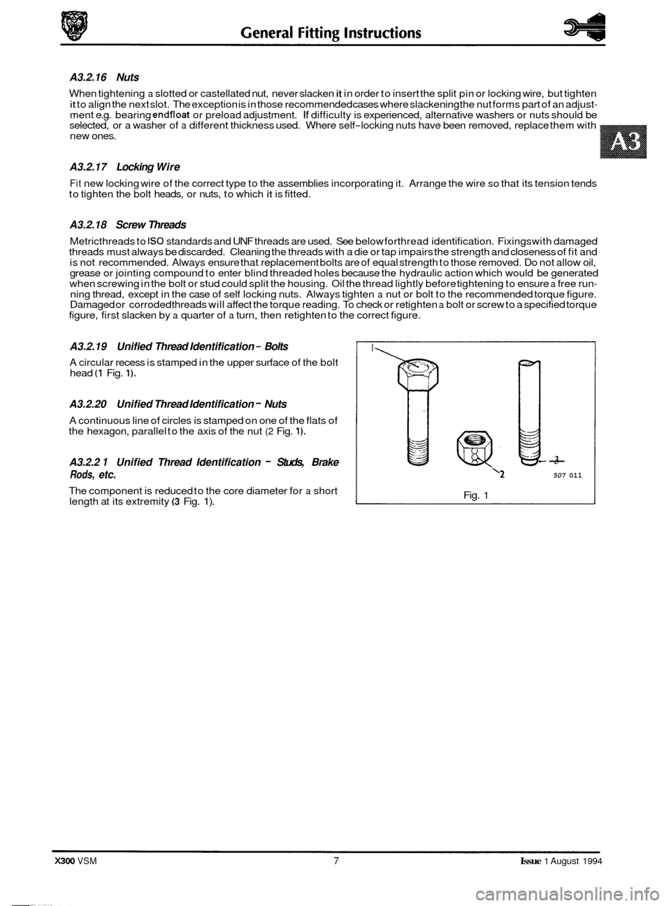
- A3.2.19 Unified Thread Identification - Bolts
A circular recess is stamped in the upper surface of the bolt
head (1 Fig. 1).
A3.2.20 Unified Thread Identification - Nuts
A continuous line of circles is stamped on one of the flats of
the hexagon, parallel to the axis of the nut (2 Fig. 1).
A3.2.2 1 Unified Thread Identification - Studs, Brake
Rods, etc.
The component is reduced to the core diameter for a short
length at its extremity (3 Fig. 1).
A3.2.16 Nuts
When tightening a slotted or castellated nut, never slacken it in order to insert the split pin or locking wire, but tighten
it to align the next slot. The exception is in those recommended cases where slackening the nut forms part of an adjust- ment e.g. bearing endfloat or preload adjustment. If difficulty is experienced, alternative washers or nuts should be
selected, or a washer of a different thickness used. Where self-locking nuts have been removed, replace them with
new ones.
A3.2.17 Locking Wire
Fit new locking wire of the correct type to the assemblies incorporating it. Arrange the wire so that its tension tends
to tighten the bolt heads, or nuts, to which it is fitted.
A3.2.18 Screw Threads
Metricthreads to IS0 standards and UNF threads are used. See below forthread identification. Fixings with damaged
threads must always be discarded. Cleaning the threads with a die or tap impairs the strength and closeness of fit and
is not recommended. Always ensure that replacement bolts are of equal strength to those removed. Do not allow oil,
grease or jointing compound to enter blind threaded holes because the hydraulic action which would be generated
when screwing in the bolt or stud could split the housing. Oil the thread lightly before tightening to ensure
a free run- ning thread, except in the case of self locking nuts. Always tighten a nut or bolt to the recommended torque figure.
Damaged or corroded threads will affect the torque reading. To check or retighten a bolt or screw to a specified torque
figure, first slacken by a quarter of a turn, then retighten to the correct figure.
I
7
-3
‘2 507 011
Fig. 1
X300 VSM 7 Issue 1 August 1994