torque JAGUAR XJ6 1994 2.G Service Manual
[x] Cancel search | Manufacturer: JAGUAR, Model Year: 1994, Model line: XJ6, Model: JAGUAR XJ6 1994 2.GPages: 521, PDF Size: 17.35 MB
Page 247 of 521

Remove the absorbent material and clean the mounting bracket and surrounding area.
Fit and align a new hydraulic control module to the mounting bracket. Ensure that the mounting cup tangs fully en-
9 Fit and tighten the securing nuts (6 Fig. 1).
. Place absorbent material underneath the hydraulic con- trol module to absorb any spillages.
. Connect the front hydraulic brake pipes (5 Fig. 1) tothe hy- drauliccontrol module, removing plugs immediately prior
to connection. Tighten the gland nuts.
Fit the PCRVs (4 Fig. 1) to the hydrauliccontrol module, re- moving plugs immediately prior to connection. Tighten
the PCRVs.
Connect the rear hydraulic brake pipes (3 Fig. 1) to the
PCRVs, removing the plugs immediately prior to connec- tion. Tighten the gland nuts.
gage
the bracket slots.
&&a: Take necessary steps to prevent rotation of the
PCRVs when fitting the rear brake pipes.
Connect
theTMC hydraulic brake pipes (2 Fig. 1) to the hy- draulic control module, removing the plugs immediately
prior to connection. Tighten the gland nuts.
. Remove the absorbent material and clean thesurrounding
area.
. Reposition and connect the multi-plug connector. Tighten
the securing bolt (1 Fig. 1).
. Ensure that all fixings are torque tightened to specified tol- erances.
. Release the brake pedal hold-down tool and remove.
. Bleed the brake system (refer to sub-section 12.4.4).
. Examine the hydraulic control module for leaks.
3 1 J70 296
Fig. 1
Issue 1 August 1994 ~~ X300 VSM
Page 248 of 521
Brakes
12.8
SRO 70.60.21
PRESSURE CONSCIOUS REDUCING VALVES - RENEW
Refer to Section 12.4, Brake System Bleeding before carrying out this procedure. Pay particular attention to the warn- ings and cautions relating to brake fluid, cleanliness and cleaning materials.
Note: The illustration shows the hydraulic control module of a 6 cyl. vehicle with traction control. Hydraulic control
modules on non-traction control vehicles have only three outlet ports. Apart from this, the removal procedure
is the same for all vehicles.
. Raise the vehicle.
Displace the bleeder screw dust cap of the front LH caliper.
The dust cap will remain captive on the bleed screw.
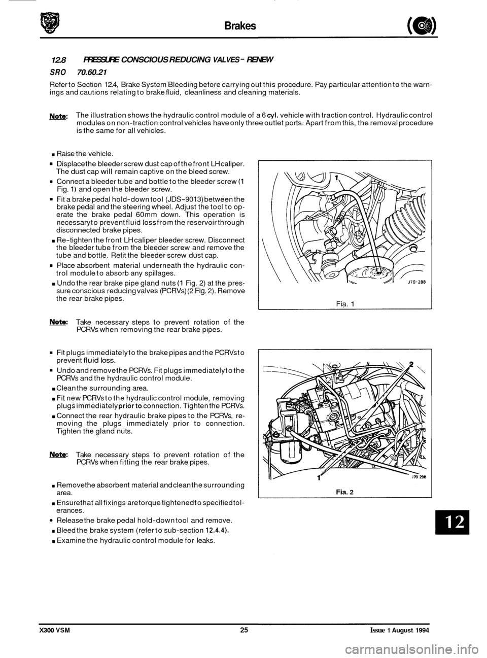
rn Connect a bleeder tube and bottle to the bleeder screw (1 Fig. 1) and open the bleeder screw.
Fit a brake pedal hold-down tool (JDS-9013) between the
brake pedal and the steering wheel. Adjust the tool to op- erate the brake pedal 60mm down. This operation is
necessary to prevent fluid
loss from the reservoir through
disconnected brake pipes.
. Re-tighten the front LH caliper bleeder screw. Disconnect
the bleeder tube from the bleeder screw and remove the
tube and bottle. Refit the bleeder screw dust cap.
rn Place absorbent material underneath the hydraulic con- trol module to absorb any spillages.
. Undo the rear brake pipe gland nuts (1 Fig. 2) at the pres- sure conscious reducing valves (PCRVs) (2 Fig. 2). Remove
the rear brake pipes.
m: Take necessary steps to prevent rotation of the
PCRVs when removing the rear brake pipes.
Fit plugs immediately to the brake pipes and the PCRVs to
Undo and remove the PCRVs. Fit plugs immediately to the
. Clean the surrounding area.
. Fit new PCRVs to the hydraulic control module, removing
plugs immediately priorto connection. Tighten the PCRVs.
. Connect the rear hydraulic brake pipes to the PCRVs, re- moving the plugs immediately prior to connection.
Tighten the gland nuts.
prevent
fluid loss.
PCRVs
and the hydraulic control module.
0
Note: Take necessary steps to prevent rotation of the
PCRVs when fitting the rear brake pipes.
. Removethe absorbent material and clean the surrounding
. Ensure that all fixings are torque tightened to specified tol-
Release the brake pedal hold-down tool and remove.
. Bleed the brake system (refer to sub-section 12.4.4).
. Examine the hydraulic control module for leaks.
area.
erances. Fia.
1
Fia. 2
X300 VSM 25 Issue 1 August 1994
Page 253 of 521
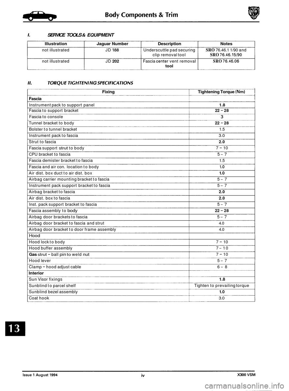
1. SERVICE TOOLS & EQUIPMENT
Illustration Jaguar Number Description Notes
not illustrated JD 188 Underscuttle pad securing SRO 76.46.1 1/90 and
not illustrated JD
202 Fascia center vent removal SRO 76.46.06
clip removal tool SRO 76.46.15190
tool
11. TORO U€ TIGHTEN1 NG SPEC1 FlCA TlONS
Fixing Tightening Torque (Nm) 1
Fascia I I
Instrument pack to support panel I 1.8 I
Fascia to support bracket
Fascia to console
3
Tunnel bracket to body
22 - 28
22
- 28
Bolster to tunnel bracket 1.5
Instrument pack to fascia
3.0
Strut to fascia 2.0
Fascia support strut to body 7 - 10
CPU bracket to fascia 5
-7
Fascia demister bracket to fascia
1.5
1 .o
1 .o
5-7
5
-7
Fascia
and air con. location to body
Air dist. box duct to air dist. box
Airbag carrier mounting bracket to fascia
Instrument pack support bracket to fascia
Airbag bracket to fascia
2.0
Air dist. box to fascia 2.0
Inst. pack support bracket to fascia 5-7
22 - 28 Fascia assembly to body
Airbag door brackets to fascia 5-7
4.0
4.0
Airbag door bracket to fascia and strut
Airbag door bracket to door frame assembly
Hood
Hood lock to body
Hood buffer assembly 7
-10
Gas strut - ball pin to weld nut
7 - 10
7
- 10
Hood lever 5
-7
Clamp
- hood adjust cable 6-8
Interior
Sun Visor fixings 1.8
Sunblind to parcel shelf
Sunblind bezel assembly
1 .o
Coat hook 3.0
Tighten to prevailing torque
Page 254 of 521
Body Components & Trim -
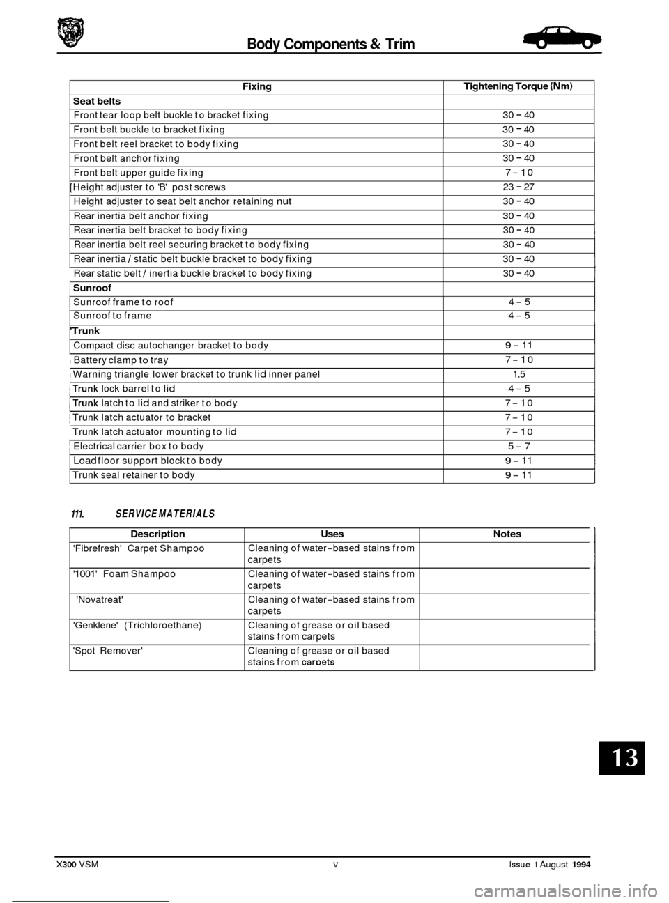
Fixing
Seat belts
Front tear loop belt buckle to bracket fixing
Front belt buckle to bracket fixing
Tightening Torque (Nm)
30 - 40
30
- 40
Front belt reel bracket to body fixing
Front belt anchor fixing 30 - 40
30 - 40
7
-10
23
- 27
30
- 40
30 - 40
30
- 40
30 - 40
30
- 40
Front belt upper guide fixing
[Height adjuster to 'B' post screws
Height adjuster to seat belt anchor retaining
nut
Rear inertia belt anchor fixing
Rear inertia belt bracket to body fixing
Rear inertia belt reel securing bracket to body fixing
Rear inertia
/ static belt buckle bracket to body fixing ~
Rear
static belt / inertia buckle bracket to body fixing
: Sunroof ~
Sunroof frame
to roof
30 - 40
4
-5
111. SERVICE MATERIALS
Sunroof to frame 4-5
'Trunk
Compact disc autochanger bracket to body
I Battery clamp to tray
I Warning triangle lower bracket to trunk lid inner panel
9- 11
7
-10
1.5
X300 VSM V Issue 1 August 1994
I trunk lock barrel to lid
j Trunk latch actuator to bracket
Trunk latch actuator mounting to
lid
j Electrical carrier box to body
Load floor support block to body
Trunk seal retainer to body
trunk latch to lid and striker to body
4-5
7
-10
7
-10
7
-10
5
-7
9- 11
9- 11
Description Uses
'Fibrefresh' Carpet Shampoo
'1001' Foam Shampoo
'Novatreat' Cleaning
of water
-based stains from
carpets
Cleaning of water
-based stains from
carpets
Cleaning of water
-based stains from
carpets
Notes
'Genklene' (Trichloroethane)
'Spot Remover' Cleaning
of grease or oil based
stains from carpets
Cleaning of grease or oil based
stains from
caroets
Page 261 of 521

Body Components & Trim -
13.2.10 Front Door Upper Trim Pad, Renew
. Disconnect vehicle battery ground lead.
. Remove the front door veneer panel.
. Remove the upper trim pad securing clip and screws.
. Lift the trim pad to release it from the door and remove the
To refit, carry out reversal of the above procedure.
inner
waist rail seal.
13.2.1 1 Front Door lower Trim Pad, Renew
. Disconnect vehicle battery ground lead.
Remove armrest.
. From inside door pocket, release guard retainer, discon-
. Carefully prise the trim pad away from the door and re-
With the trim pad moved for access, disconnect loud-
. Feed guard lamp harness through aperture and place trim
. Remove front door pocket and trim pad retainers.
. To refit, carry out reversal of the above procedure. Check
the trim pad retainers for damage before refitting.
nect
multi
-plug and remove lamp.
lease from the upper retainer.
speaker and window
lift switch multi-plugs.
pad on a clean workbench.
13.2.12 Door lock Barrel, Renew
. Disconnect vehicle battery ground lead.
. Remove the door trim veneer, door upper trim pad, door
. Remove the handle assembly to a clean workbench.
. Remove the lock barrel from its bayonet type mounting.
. Carefully remove the barrel components noting the order
. To refit, carry out reversal of the above procedure, ensur-
lower trim pad and door handle.
and position if reassembly is required.
ing that the components are lightly greased.
13.2.13 Front or Rear Door Lock Striker, Renew
. Note position of striker before removal.
. Remove two screws attaching striker to pillar.
Remove striker from pillar.
. To refit, carry out reversal of the above procedure, ensur- ing that the striker is correctly aligned with the door lock
before final torque tightening.
13.2.14 Front or Rear Door Outer Handle Operating
Rod, Renew
. Disconnect vehicle battery ground lead.
. Remove the door trim veneer, door upper trim pad, door
lower trim pad.
. Disengage the handle operating rod retaining clip and free
the rod from the operating pivot.
. Allowthe latch levertocontact the release mechanism, re- position the operating rod and replace the retaining clip.
. Check that the setting is correct by operating the door
mechanism.
To refit, carry out reversal of the above procedure.
/ 2 176 -1053
1. Water shedder 2. Multi connector 3. Armrest support
Fig. 1 Door Interior Components
Issue 1 August 1994 6 X300 VSM
Page 290 of 521

Body Components & Trim -
13.3.32 'A' Post lower Trim Pad, Renew
SRO 76.13.30
. Locally displace the draught welting from the front door
= Undo and remove the 'A' post lower trim pad quarter turn
. Displace and remove the 'A' post lower trim pad by pulling
. Fit and seat the new 'A' post lower trim pad, engaging the
. Fit and secure the 'A' post lower trim pad quarter turn fas-
Reposition and fully seat the draught welting to the front
aperture
flange.
fastener. rearwards to disengage clips and place aside.
clips on the front door flange.
tener. door aperture flange.
13.3.33 Rear Quarter Upper Trim Pad, Renew
. Remove the rear seat belt upper anchorage RH or LH.
. Remove the trim pad securing screw.
. Slacken but do not remove thecombined grab handle and
. Unclip the rear quarter trim pad and remove.
. To refit, carry out reversal of the above procedure, noting
that seat belt fixings must be tightened to the specified
torque.
coat hook securing screws.
13.3.34 'B' Post Upper Trim Pad, Renew
. Position front seat and squab fully forward.
. Remove seat belt lower anchorage and feed the belt
through the lower trim aperture.
. Remove seat belt upper anchorage.
. Remove trim finisher upper seat belt aperture and door
. Release upper trim pad from its fixings by exerting down-
. To refit, carry out reversal of the above procedure.
aperture edge
trim.
ward pressure.
WARNING: ENSURE THAT THE SEAT BELT IS CORRECTLY
ASSEMBLED AND FlXlNGS TORQUE TIGH-
0 TENED.
13.3.35 'B' Post lower Trim Pad, Renew
. Position front seat and squab fully forward.
Remove seat belt lower anchorage and feed the belt
. Release trim pad quarter turn fasteners and remove trim
Remove fasteners from trim pad as required.
= To refit, carry out reversal of the above procedure.
through the lower
trim aperture.
pad.
WARNING: ENSURE THAT THE SEAT BELT IS CORRECTLY
ASSEMBLED AND FlXlNGS TORQUE TIGH- TENED.
X300 VSM 35 Issue 1 August 1994
Page 297 of 521
Body Components & Trim a
13.5 HOOD
13.5.1 Hood, Description
The hood is fitted with black moulded covers over the inner fenders and behind the headlamp units; the right hand
fender cover incorporates compartments for spare fuses and tool kit (where fitted). Two gas struts attached by press- on fittings on the body and hood support the hood cover.
13.5.2 Plenum Chamber Finisher, Renew
SRO 76.10.01
9 Open the hood and fit suitable fender cover.
. Remove the wiper arm, see section 15.6.
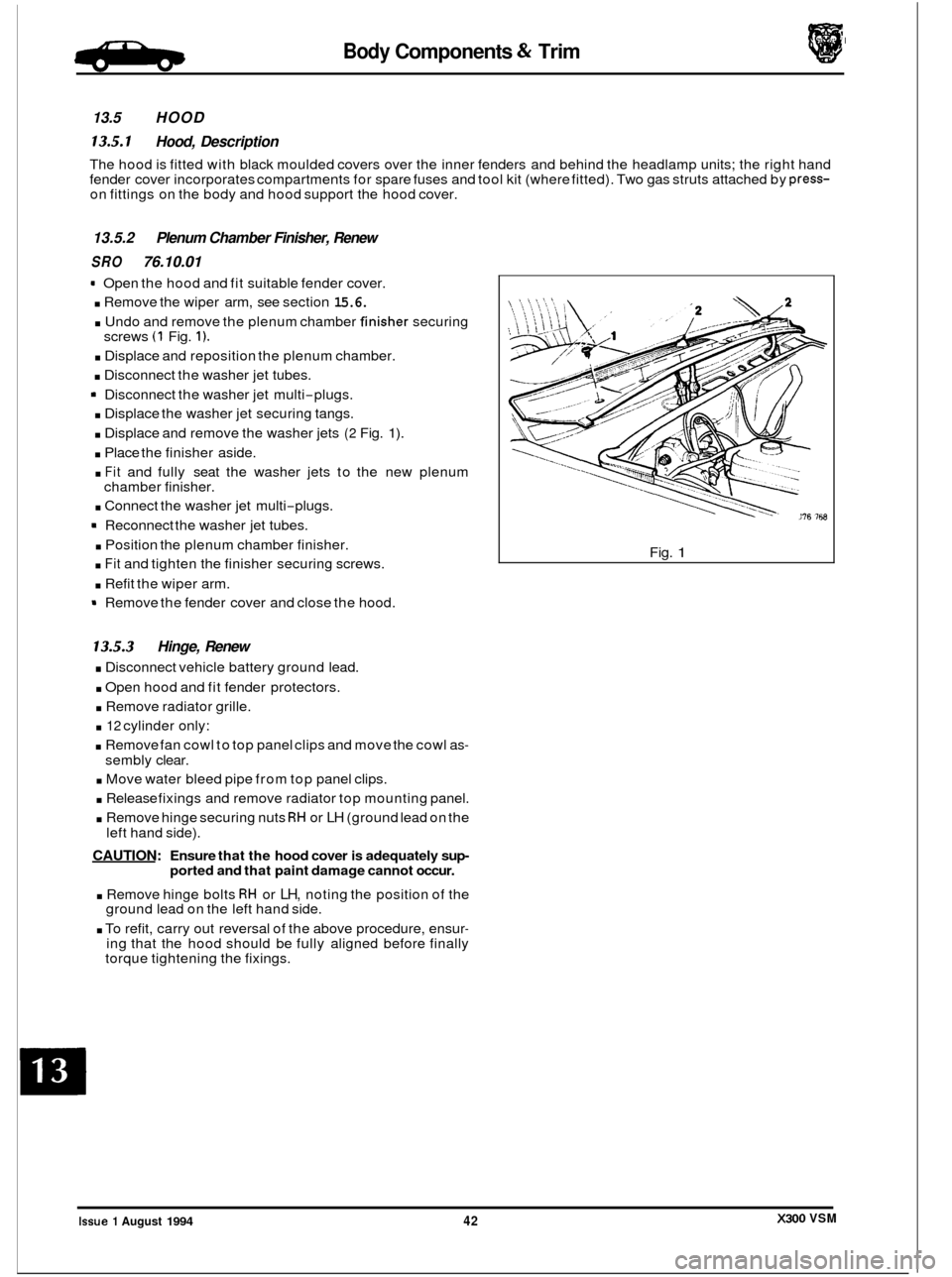
. Undo and remove the plenum chamber finis..er securing
. Displace and reposition the plenum chamber.
. Disconnect the washer jet tubes.
9 Disconnect the washer jet multi-plugs.
. Displace the washer jet securing tangs.
. Displace and remove the washer jets (2 Fig. 1).
. Place the finisher aside.
. Fit and fully seat the washer jets to the new plenum
. Connect the washer jet multi-plugs.
9 Reconnect the washer jet tubes.
. Position the plenum chamber finisher.
. Fit and tighten the finisher securing screws.
. Refit the wiper arm.
9 Remove the fender cover and close the hood.
screws
(1 Fig. 1).
chamber
finisher.
13.5.3 Hinge, Renew
. Disconnect vehicle battery ground lead.
. Open hood and fit fender protectors.
. Remove radiator grille.
. 12 cylinder only:
. Remove fan cowl to top panel clips and move the cowl as-
sembly clear.
. Move water bleed pipe from top panel clips.
. Release fixings and remove radiator top mounting panel.
. Remove hinge securing nuts RH or LH (ground lead on the
CAUTION: Ensure that the hood cover is adequately sup- ported and that paint damage cannot occur.
. Remove hinge bolts RH or LH, noting the position of the
ground lead on the left hand side.
. To refit, carry out reversal of the above procedure, ensur- ing that the hood should be fully aligned before finally
torque tightening the fixings.
left
hand side).
I
0
Fig. 1
X300 VSM Issue 1 August 1994 42
Page 303 of 521
Body Components & Trim a
13.8 SEATING AND SEAT BELTS
13.8.1 Seating, Description
The front seats are available in a range of materials consisting of sculptured fabric / leather, leather, sports cloth / leather, embossed leather / leather and autolux. Both seats are available as 'manual', ie manually adjustable with elec- tric rise and fall, manual height adjustment headrests, 'power', ie 12-way electric adjustment, 'power with memory', ie memory controlled, 12-way electric adjustment of seat, steering column and exterior rear view mirrors and 'heated',
ie with integral heating.
Front seats are based on a non
-handed, one-piece frame which includes cushion and squab frames and seat adjuster
mechanisms. The seat switchpacks (powerseats) are fitted to the outboard side of driver and passenger seats; on 'man- ual'seats, the seat height adjustment switch is similarly located. Seat control modules SCMs are contained within the
seat assemblies. The seats are secured through four mounting points to the vehicle floor.
Rear seats are of the bench type with
full width removable cushion and individual seat squabs.
Electrical components installed on the heel board below the rear passenger seat are protected
by two covers secured
by two locating brackets on the floor and by two latches on the cover. The latches are released by pushing down on
the two recesses in the top edge of the cover.
13.8.2 Front Manual Seat, Renew
. Disconnect vehicle battery ground lead.
. Disconnect electrical connections as required.
. Remove the seat forward fixings.
Move the seat fully forward.
. Remove the rear fixing / slide covers.
. Remove the seat rear fixings.
. Reposition seat for access and remove seat from vehicle.
. To refit seat, carry out reversal of above procedure.
13.8.3
. Disconnect vehicle battery ground lead.
. Move the seat fully forward to gain access to squab back
Remove squab side fixings, disconnect lamp harness and
. To refit, carry out reversal of the above procedure.
Front Seat (Power Operated) Squab Back
Cover, Renew
cover outer fixings.
remove squab back cover.
13.8.4
. Position seat as required for access.
. Disconnect vehicle battery ground lead.
. Release sound insulation retainers and displace insula-
. Remove SCM cover, move SCM aside and remove seat
. Remove the seat forward fixings and move the seat fully
. Remove the seat rearward fixing covers and remove the
. Disconnect multi-plugs, seat switch and motor harness to
. Release harness tie strap and remove seat assembly from
Front Seat (Power Operated), Renew
tion.
switch
multi-plug from its mounting bracket.
forward. seat rearward fixings.
SCM.
vehicle.
. To refit, carry out reversal of the above procedure, ensur- ing that fixings are tightened to the correct torque.
Issue 1 August 1994 48 X300 VSM
0
0
0
Page 307 of 521

Body Components & Trim
0 13.8.1 1 Front Seat Belt Buckle Unit, Renew
. Disconnect vehicle battery ground lead.
. Remove the front seat cushion.
. Disconnect cable connector and remove cable into seat
frame.
. Remove securing bolt, buckle unit and wavy washer.
. To refit, carry out reversal of the above procedure.
13.8.12 Front Seat Belt, Renew
. Position the front seat for access.
. Disconnect vehicle battery ground lead.
. Release 'B' post upper trim and belt aperture cover.
. Remove cover from seat belt upper fixing.
. Removeseat belt upper fixing and releaseseat belt anchor
. Lower the upper trim pad with seat belt onto the seat.
Remove 'B' post lower trim.
. Remove seat belt lower fixing, disconnect anchor plate
and remove wavy washer.
. Release upper trim pad from seat belt. Remove upper
guide fixings at 'B' post.
. Remove seat belt reel fixings and remove reel and belt as- sem bly.
. Refit seat cushion.
Secure seat belt reel to the specified torque.
Fit and secure upper guide plate to 'B' post.
Pass the seat belt through the upper trim pad.
. Fit wavy washerto lower anchor,fit lower anchor plate and
. Refit lower 'B' post trim panel.
. Refit upper 'B' post trim panel.
from
height adjuster; remove wavy washer.
0
nut; tighten to specified torque.
Place wavy washer
on height adjuster stud, fit belt upper
anchor and nut; tighten to specified torque.
. Fit plastic cover and split finisher.
13.8.13 Rear Inertia Seat Belt, Renew
= Remove seat cushion, rear seat squab and rear parcel tray.
. Remove foam pad from rear shelf and remove seat belt
. Remove buckle assembly, washers and spacers.
. Remove side seat belt buckle and the lower anchorage
. Move the belt aside and remove the upper spacer.
Remove theseat belt bracket/ body fixing and remove reel
= Remove seat belt reel / securing bracket fixings.
. Remove the reel and belt assembly.
. To refit, carry out reversal of the above procedure.
0 buckle bolt.
belt.
/ bracket assembly.
m
Issue 1 August 1994 52 X300 VSM ~~
Page 311 of 521

Climate Control Systems
Illustration 1 JaguarNumber I Deription Not-
not i II ustrated
11. TORQUE TIGHTEN1 NG SPEC1 FICATIONS
Recovery 1 Recycling 1 Recharging
station See
standards
fixing
Blower assembly to body
Condenser to receiver
1 drier (tube nut)
lightening Torque
I (Nm)
4-7
14
- 18
Hoses to evaporator plate
Liquid line to receiver
1 drier (tube nut)
I Discharge hose to condenser (tube nut) I 22 - 28 I
7 - 10
14- 18
I Heater 1 cooler case to body I 5-7 I
I Hoses to compressor I 7-10 I
I Mountina strut to heater / cooler case I 5-7 I
X300 VSM Issue 1 August 1994 ii