torque JAGUAR XJ6 1994 2.G Owner's Guide
[x] Cancel search | Manufacturer: JAGUAR, Model Year: 1994, Model line: XJ6, Model: JAGUAR XJ6 1994 2.GPages: 521, PDF Size: 17.35 MB
Page 158 of 521

Powertrain Automatic Transmission (V12 & AJ16 Supercharged)
Light throttle D1 -D2 D2 - D3 D3 - D4
Normal mile 1 h 8- 10 18-20 25 - 39
kmlh 13- 15 28 - 33 40 - 46
sport mile 1 h 10 - 12 20 - 23 30 - 34
kmlh 16- 19 32 - 37 48-55
Up to Detent D1- D2 D2 - D3
Normal mile I h 34 - 37 60-66
kmlh 54 - 59 97 - 107
8.2.1.2 Shift Speeds
0
D4 - TCC on
45 - 51
72
-83
47
- 55
76
-88
D3
- D4
86
-94
138
- 151
4,O Liter Supercharged
sport mile I h 43 - 47 74 - 81 103 - 113
kmlh 69 - 76
118- 130
166 - 182
Maximum shift speeds (through detent)
Normal 1 Sport mile I h
kmlh
D1 -D2 D2 - D3 D3 - TCC on
47 - 50 81 -84
116 - 128
75
- 80 130 - 134
187 - 205
TCC
-Torque converter clutch
m: Road speeds shown above are for a vehicle with an axle ratio of 3,58:1, and standard tyres (2251 65ZR15). For
a vehicle with optional sports tyres
(225 / 55ZR16) (lattice wheels), these speeds must be reduced by 2,4%.
Zero throttle 1 TCCoffinD4 1 D4 - D3 D3 - D2
X300 VSM 3 Issue 1 August 1994
D2 - D1
Normal mile 1 h
kmth
sport mile 1 h
kmlh
I 36 - 40 15- 17
10- 12 -
58-64 24 - 27 16- 19 -
36 - 40 18 - 20 12 - 14
9-9
58-64 29 - 32 20 - 22 14 - 15
Up to
detent D4 - D3 03 - D2
Normal mile 1 h 67-74 3-44
kmlh 107-118 63-70
sport mile 1 h 81 -89 57 - 63
kmlh 130- 144 92 - 101
Kick-down available (through detent) TCC4 - D3 D3 - 02
Normal 1 Sport mile I h 103- 113 67 -74
kmlh 165 - 183 107 - 118 D2
- D1
9-9
14
- 15
27
- 29
43 - 47
D2
- D1
36 - 40
58-64
Page 159 of 521

Automatic Transmission (V12 & AJ16 Supercharged)
Light throttle D1 -D2
Normal mile 1 h -
km/h -
sport mile / h 10- 12
kmlh 16- 18
Up to detent
Normal mile I h
kmlh
sport mile
1 h
km/h
Maximum shift speeds (through detent)
Normal I Sport mile / h
kmlh
6,O Liier
D2 - D3
D3 - D4
D4 - TCC on
20 - 23 29 - 33
48 - 55
32
- 37 46 - 52
77 -88
23 - 26 32 - 37 51 -59
36
- 41 51 -59 82 - 94
D1 -D2
D2 - D3 D3 - D4
35
- 40 61 -70 83-91
56
- 64 98- 112 133 - 164
43 - 49 73 - 79 99 -107
68
-78 117 - 127 158 - 172
D1 -D2 D2 - D3
D3 - TCC on
48-53 81 -89
116- 124
77
- 85 130- 149
186 - 198
Zero throttle
Normal mile 1 h
kmlh
sport mile
1 h
km/h
TCC off in 04 D4 - D3 D3 - D2 D2 - D1
- 36 - 40 15 - 17 10 - 12
16
- 19 58 - 64 24 - 27
36
- 40 18 - 20 12-14 6-7
58
- 64 29 - 32 19 - 22 10- 12
-
0
0
Up to detent
Normal mile I h
kmlh
sport mile
/ h
km/h
mile I h
kmlh
'Kick-down' available (through detent)
Normal 1 Sport
TCC -Torque converter clutch
m: Road speeds shown above are for a vehicle with an axle ratio of 3,58:1, and standard tyres (2251 65ZR15). For
a vehicle with optional sports tyres
(225 155ZR16) (lattice wheels), these speeds must be reduced by 2,4%.
D4 - D3 D3 - D2 D2 - D1
67 - 75 37 - 41 7-9
108
- 119 59 - 66 11 - 14
84
-92 60 - 66
27 - 29
134
- 148 96 - 106
43 - 47
TCC4
- D3 03 - D2 D2 - D1
103 - 113 67 -75 36 - 40
164
- 181 108 - 119 58 - 64
0
0
Issue 1 August 1994 4 X300 VSM
Page 183 of 521
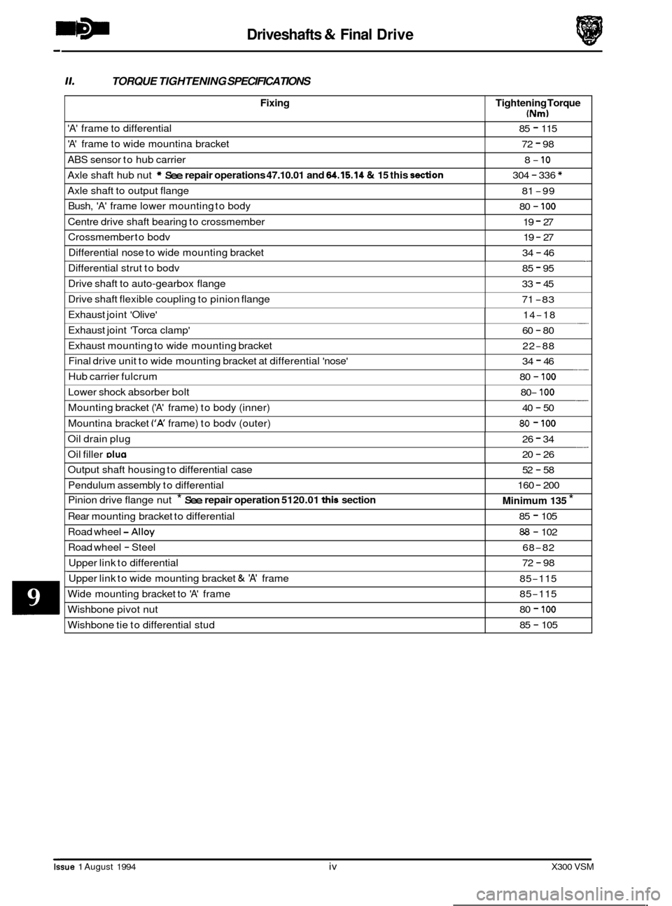
-5 Driveshafts & Final Drive
0
Fixing
11. TORQUE TIGHTENING SPECIFICATIONS
Tightening Torque
(Nm)
'A' frame to differential 85 - 115
'A' frame to wide mountina bracket 72 - 98
ABS sensor to hub carrier
Axle shaft hub nut
* See repair operations 47.10.01 and 64.15.14 & 15 this don
8- 10
304 - 336 *
Axle shaft to output flange
Bush,
'A' frame lower mounting to body
81 -99
80
- 100
Centre drive shaft bearing to crossmember 19 - 27
Crossmember to bodv 19 - 27
Differential nose to wide mounting bracket - 34 - 46
Issue 1 August 1994 iv X300 VSM
Differential strut to bodv 85 - 95
Drive shaft to auto-gearbox flange
Drive shaft flexible coupling to pinion flange 33 - 45
71
-83
Exhaust joint 'Olive'
Exhaust joint 'Torca clamp' -. 14-18
60
- 80
Exhaust mounting to wide mounting bracket
Final drive unit to wide mounting bracket at differential 'nose'
Hub carrier fulcrum 22-88
34
- 46
80
- 100 ___
Lower shock absorber bolt
Mounting bracket
('A' frame) to body (inner)
Mountina bracket
('A' frame) to bodv (outer)
- 80- 100
40 - 50
80 - 100
Oil drain plug __ 26 - 34
Oil filler DIU~ 20 - 26
Output shaft housing to differential case
Pendulum assembly to differential
Pinion drive flange nut
* See repair operation 5120.01 this section
Road wheel -Alloy
Road wheel - Steel
Upper link to differential
Rear
mounting bracket to differential
52 - 58
160
- 200
Minimum 135 *
85 - 105
88 - 102
68
-82
72
- 98 ~~~~~
Upper
link to wide mounting bracket & 'A' frame
Wide mounting bracket to
'A' frame
85-115
85
-115
Wishbone pivot nut
Wishbone tie to differential stud 80 - 100
85 - 105
Page 189 of 521
Driveshafts & Final Drive
9.3
SRO 51.10.24
Disconnect vehicle battery ground lead.
. Support the vehicle at the rear.
OUTPUT SHAFT END FLOAT, CHECK
Mount a dial test indicator (DTI) to the differential housing with the probe resting on the output shaft flange (DTI probe must be parallel to the output shaft center line and NOT at an angle).
. Push the wheel 1 shaft assembly inwards and zero the DTI; pull outwards and note the reading.
. If the end float exceeds 0,15 mm; firstly verify the shim preload and if this is found to be correct, renew the output
shaft bearing. See 51.10.22. this section, for shim check and renew operations.
9.4
SRO 51.20.19
rn Disconnect vehicle battery ground lead.
See operation 51.10.22. this section, for process detail, less bearing 1 oil seal renew.
OUTPUT SHAFT HOUSING ‘0’ RING, RENEW
Prior to removal of shaft assembly check output shaft end float in accordance with operation 51.10.24.
9.5 OIL SEAL - PINION FLANGE, RENEW
SRO 51.20.01
. Disconnect vehicle battery ground lead.
. Support the vehicle at the rear.
. Disconnect main handbrake cable at compensator.
’Match mark‘ the FLEXIBLE COUPLING to the differential DRIVE FLANGE and remove fixings.
Remove fixings center bearing to crossmember and push drive shaft rear section forward to disengage from pinion
spigot.
CAUTION: Under no circumstances must the flexible coupling (or its fixings) be loosened or removed from the drive
shaft flange.
Support the drive shaft, do not allow it to hang.
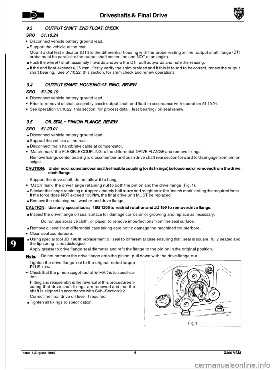
9 ‘Match mark‘ the drive flange retaining nut to both the pinion and the drive flange (Fig. 1).
. Slacken the flange retaining nut approximately half a turn and retighten to the ‘match mark‘ noting the required force.
. Remove the retaining nut, washer and drive flange.
CAUTION: Use only special tools; 18G 1205 to restrict rotation and JD 156 to remove drive flange.
. Inspect the drive flange oil seal surface for damage corrosion or grooving and replace as necessary.
. Remove oil seal from differential case taking care not to damage the machined counterbore.
rn Clean seal counterbore.
. Using special tool JD 198 fit replacement oil seal to differential case ensuring that, seal is square, fully seated and
If the force does NOT exceed 135 Nm, the final drive unit MUST be replaced.
Do not use abrasive cloth, or paper, to remove imperfections from the seal surface.
the
lip spring is not dislodged.
Apply grease to drive flange seal diameter and refit the flange to the pinion in the original position.
U: Do not hammer the drive flange onto the pinion; pull down with the drive flange nut.
Tighten the drive flange nut to the original noted torque PLUS 10%.
* Check that the pinion spigot radial run-out is to specifica- tion.
Fitting and reassembly is the reversal of this procedure en
- suring that drive shaft fixings are renewed and that the
shaft is aligned in accordance with Sub-Section 9.2.
Correct the final drive oil level if required.
. Tighten all fixings to specification.
Fig. 1
0
Issue 1 August 1994 4 X300 VSM
Page 192 of 521
Driveshafts & Final Drive
. Remove upper link assembly from differential and wide mounting bracket / 'A' frame.
. Release fixings, 'A' frame to differential, 'A' frame to wishbone tie and wide mounting bracket to 'A' frame.
. Remove wishbone tie assembly, rear mounting bracket and pendulum assembly.
. Release fixings differential nose to wide mounting bracket.
. Assembly and fitting is the reversal of this procedure, taking note of the following:
Drive shaft must be aligned in accordance with Sub
-Section 9.2.
Renew all self locking nuts.
Renew all bolts that were originally fitted with thread locking adhesive.
Replace all locking wire and split pins (cotter pins).
Tighten all fixings to the specified torque.
Correct the final drive oil level
if required.
Check and adjust rear wheel camber setting as required.
9.9 AXLE SHAFT ASSEMBLY, RENEW
SRO
47.10.01
Disconnect vehicle battery ground lead.
. Slacken appropriate axle shaft hub nut.
. Support the vehicle at the rear and remove rear road
. Remove brake caliper in accordance with 70.55.03. Sec-
wheel.
tion 12, but do not disconnect hydraulics.
Slacken hub carrier fulcrum and remove ABS sensor from
hub carrier.
. Remove axle shaft hub nut and collar.
. Remove fixings axle shaft to differential output shaft
flange, note camber shim.
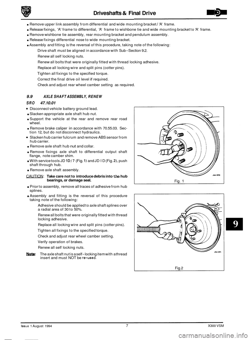
. With service tools JD 1D/7 (Fig. 1) and JD ID (Fig. 21, push
shaft through hub.
. Remove axle shaft assembly.
CAUTION: Take care not to introduce debris into the hub
bearings, or damage seal.
. Prior to assembly, remove all traces of adhesive from hub
. Assembly and fitting is the reversal of this procedure
Adhesive should be applied to axle shaft splines over
a radial area of
30 to 50%.
Renew all bolts that were originally fitted with thread
locking adhesive.
Replace all locking wire and split pins (cotter pins).
Tighten all fixings to the specified torque.
Check and adjust rear wheel camber setting.
Verify operation of brakes.
Renew all self locking nuts.
splines.
taking
note of the following:
0
NQ&: The axle shaft nut is a self-locking item with a thread
insert and must NOT be reused.
Fig. 1
Fig.2
- Iss ue 1 August 1994
__~
7 X300 VSM
Page 198 of 521
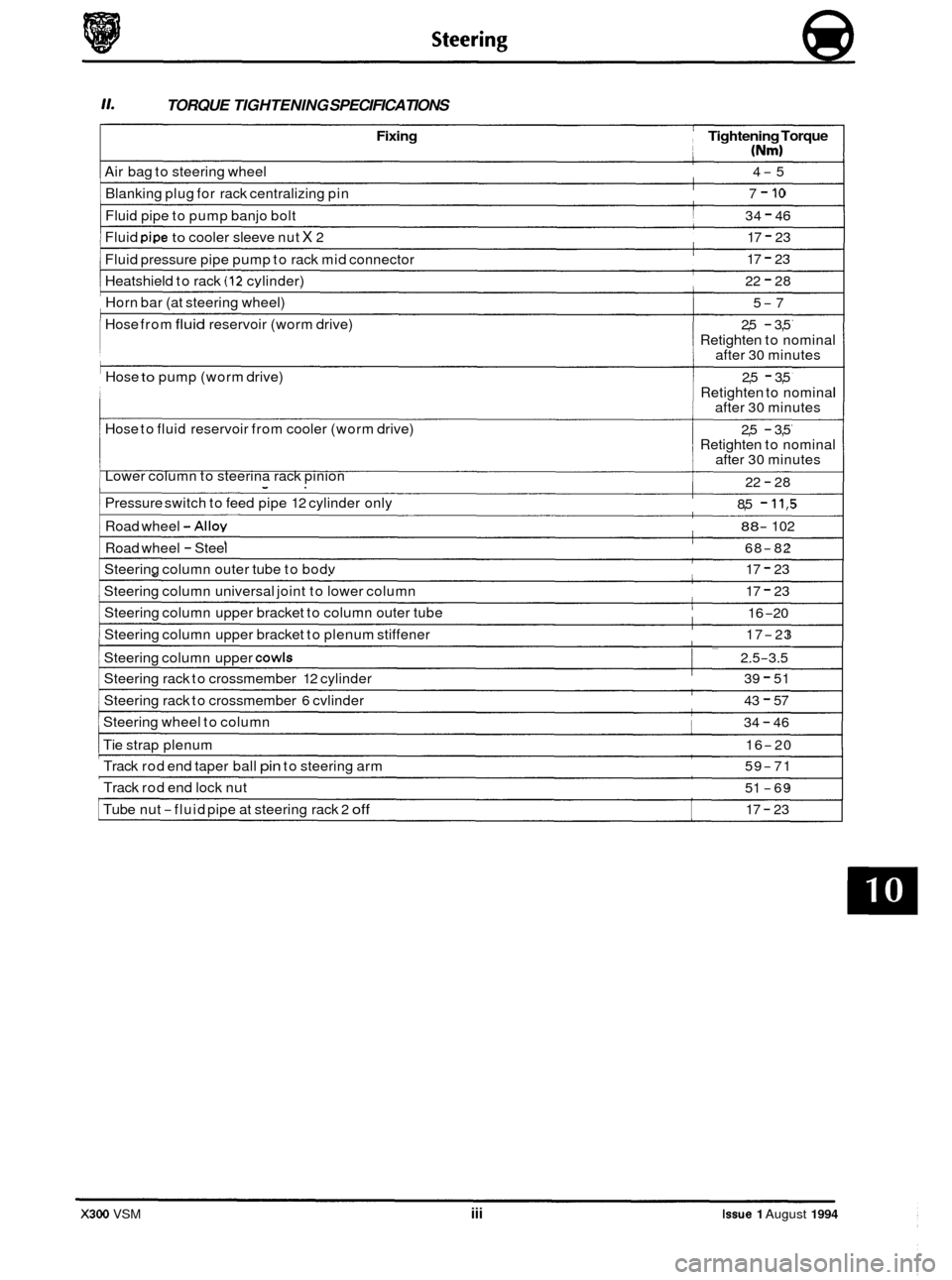
TORQUE TIGHTENING SPECIFICATIONS
Fixing Tightening Torque
(Nm)
Air bag to steering wheel
Blanking plug for rack centralizing pin 4-5
7
- 10
Fluid pipe to pump banjo bolt
Fluid
pipe to cooler sleeve nut X 2 34
- 46
17
- 23
Fluid pressure pipe pump to rack mid connector
Heatshield to rack
(12 cvlinder)
17 - 23
22
- 28
Horn bar (at steering wheel)
Hose from
fluid reservoir (worm drive)
Hose
to pump (worm drive)
Hose to fluid reservoir from cooler (worm drive)
Lower column to steerina rack pinion
5-7
2,5
- 3,5
Retighten to nominal
after 30 minutes
Retighten to nominal
after
30 minutes
Retighten to nominal
after
30 minutes
2,5 - 3,5
2,5
- 3,5
22
- 28
Pressure switch to feed pipe 12 cylinder only 8,5 - 11,5
Road wheel -Alloy 88- 102
Road wheel - Steel 68-82
Steering column outer tube to bodv 17 - 23
Steering column universal joint to lower column
Steering column upper bracket to column outer tube
Steering column upper bracket to plenum stiffener 17 - 23
16
-20
17
-23 ~~
I Steering
column upper COWIS I ~ 2.5-3.5
Steering
rack to crossmember 12 cylinder
Steering rack to crossmember
6 cvlinder
39 - 51
43
- 57
Steering wheel to column 34 - 46
Tie strap plenum 16-20
Track rod end taper ball pin to steering arm
Track rod end lock nut 59-71
51
-69
17
- 23 Tube nut -fluid pipe at steering rack 2 off
X300 VSM iii Issue 1 August 1994
Page 212 of 521

Suspension Systems
Not illustrated
1. SERVICE TOOLS & EQUIPMENT (continued)
JD199
0
Fixing
To be issued
Tightening Torque
(Nm)
JD199-1 Not i II ustrated
Description US98
LM Multi - purpose grease
Molib Alloy
PI907 No1
Molykote 11 1
Lower damper bolt
Wishbone to crossmember fulcrum shaft
Stabilizer mounting bushes
& rear damper top
guide bush
Caliper to carrier bolts
/ guide pins
Description
Notes
Adaptor Remover / Renewer
Suspension Bushes (Bottom Front
Wishbone Inner)
____~ ~ Spring
Compressor Rear Suspension
Damper Retaining Tie Rear
Suspension
Adaptor
Replacer Rear Hub Pivot
Bearing Cup
Driver Handle
Adaptor Remover
Main Shaft Pilot
Bearing Outer Track
Impulse Extractor (slide Hammer)
UNF. Basic Tool
Notes
Issue 1 August 1994 X300 VSM iii
Page 216 of 521
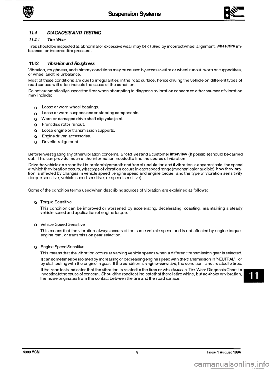
may include:
0
0
Loose or worn wheel bearings.
Loose or worn suspensions or steering components.
0 Worn or damaged drive shaft slip yoke joint.
0 Front disc rotor runout.
o Loose engine or transmission supports.
0 Driveline alignment.
0 Engine driven accessories.
Suspension Systems
11.4 DIAGNOSIS AND TESTING
' 11.4.1 Tire Wear
Tires should be inspected as abnormal or excessive wear may becaused by incorrect wheel alignment, wheelbire im- balance, or incorrect tire pressure.
1 1.4.2 vibration and Roughness
Vibration, roughness, and shimmy conditions may be caused by excessive tire or wheel runout, worn or cupped tires,
or wheel and tire unbalance.
Most of these conditions are due to irregularities in the road surface, hence driving the vehicle on different types of
road surface will often indicate the cause of the condition.
Do not automatically suspect the tires when attempting to diagnose a vibration concern as other sources of vibration
Before investigating any other vibration concerns,
a roaG &est and a customer inter\,.dw (if possible) should be carried
out. This can provide much of the information needed to find the source of vibration.
Drive the vehicle on a road that is preferably smooth and free of undulation and
if vibration is apparent note, the speed at which thevibration occurs, whattype of vibration occurs in each speed range (mechanical or audible), howthevibra- tion is affected by changes in vehicle speed , engine speed and engine torque, and the type of vibration sensitivity
(torque sensitive, vehicle speed sensitive, or speed sensitive).
Some of the condition terms used when describing sources of vibration are explained as follows:
0 Torque Sensitive
This condition can be improved or worsened by accelerating, decelerating, coasting, maintaining
a steady
vehicle speed and application of engine torque.
0 Vehicle Speed Sensitive
This means that the vibration always occurs at the same vehicle speed and is not affected by engine torque,
engine rpm, or transmission gear selection.
B
0 Engine Speed Sensitive
This means that the vibration occurs
at varying vehicle speeds when a different transmission gear is selected.
It can sometimes be isolated by increasing or decreasing engine speed with the transmission in 'NEUTRAL', or
by stall testing with the engine in gear. If the condition is enginesensitive, the condition is not related to tires.
If the road tests indicates that the vibration is related to the tires or wheels,use a 'lire Wear Diagnosis Chart' to
investigate the cause of concern. Should the road test indicate that there is tire whine, but noshake or vibration,
the noise originates from the contact between the tire and the road surface.
X300 VSM 3 Issue 1 August 1994
Page 223 of 521

1. SERVICE TOOLS & EQUIPMENT
Description
Parking brake cable remover
Illustration
Notes
not
illustrated
Pipe connectors to hydraulic module:
M12
M10
Jaguar Number
JD.142
15
- 19
12 - 16
186.672
Description
U-
Molykote 11 1 Caliper to carrier securing bolts
6947017
Notes
JDS.9013
Replacer disc brake
piston seal
I
Brake hose clamp, Girling
Brake pedal hold down tool
11. TORQUE TIGHTENING SPECIFICATIONS
Fixing 1 Tightening Torque
(Nm)
Vacuum booster to pedal box I 21 -29 I
Tandem master cylinder to booster I 21 -29 I
Hvdraulic module to module bracket I 18 - 26 I
Caliper guide pins I 25 - 35 I
Caliper to vertical link I 120 - 160 I
Caliper to hub carrier I 54 - 66 I
111. SERVICE MATERIALS
Iv. SERVICE DATA
Front brake disc run out
Front brake
disc parallelism
Rear brake disc
run out
Rear brake disc parallelism 0.101
mm (0.004 in) max.
0.0127mm (0.0005in) max.
0.101
mm (0.004 in) max.
0.0127mm (0.0005in) max.
Issue 1 August 1994 ii X300 VSM
Page 240 of 521
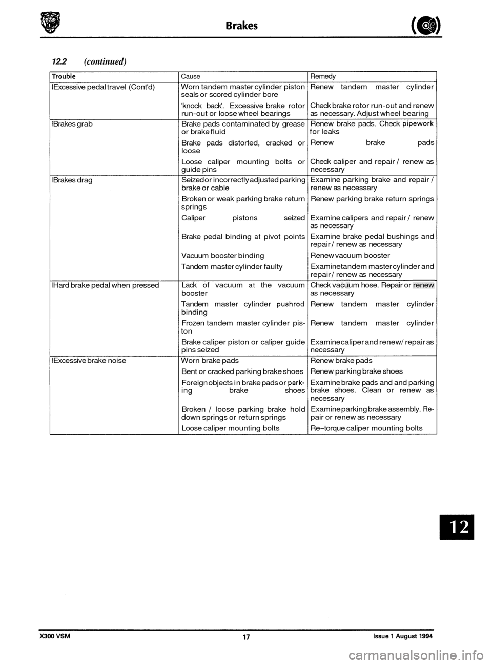
12.2 (continued)
rrouble
Excessive pedal travel (Cont'd)
Brakes grab
Brakes drag
Hard brake pedal when pressed
Excessive brake noise
Cause
Worn tandem master cylinder piston
seals or scored cylinder bore
'knock back'. Excessive brake rotor
run
-out or loose wheel bearings
Brake pads contaminated by grease
or brake fluid
Brake pads distorted, cracked or
loose
Loose caliper mounting bolts or
guide pins
Seized or incorrectly adjusted parking
brake or cable
Broken or weak parking brake return
springs
Caliper pistons seized
Brake pedal binding
at pivot points
Vacuum booster binding
Tandem master cylinder faulty
Lack of vacuum
at the vacuum
booster
Tandem master cylinder
pushrod
binding
Frozen tandem master cylinder pis
-
ton
Brake caliper piston or caliper guide
pins seized
Worn brake pads
Bent or cracked parking brake shoes
Foreign objects in brake pads or
park- ing brake shoes
Broken
/ loose parking brake hold
down springs or return springs
Loose caliper mounting bolts
Remedy
Renew tandem master cylinder
Check brake rotor run
-out and renew
as necessary. Adjust wheel bearing
Renew brake pads. Check
pipework for leaks
Renew brake pads
Check caliper and repair
/ renew as
necessary
Examine parking brake and repair
/
renew as necessary
Renew parking brake return springs
Examine calipers and repair
/ renew
as necessary
Examine brake pedal bushings and
repair
/ renew as necessary
Renew vacuum booster
Examine tandem master cylinder and
repair
/ renew as necessary
Check vacuum hose. Repair or renew
as necessary
Renew tandem master cylinder
Renew tandem master cylinder
Examine caliper and renew/ repair as
necessary
Renew brake pads
Renew parking brake shoes
Examine brake pads and and parking
brake shoes. Clean or renew as
necessary
Examine parking brake assembly.
Re- pair or renew as necessary
Re
-torque caliper mounting bolts