JEEP CHEROKEE 1994 Service Repair Manual
Manufacturer: JEEP, Model Year: 1994, Model line: CHEROKEE, Model: JEEP CHEROKEE 1994Pages: 1784, PDF Size: 77.09 MB
Page 1151 of 1784
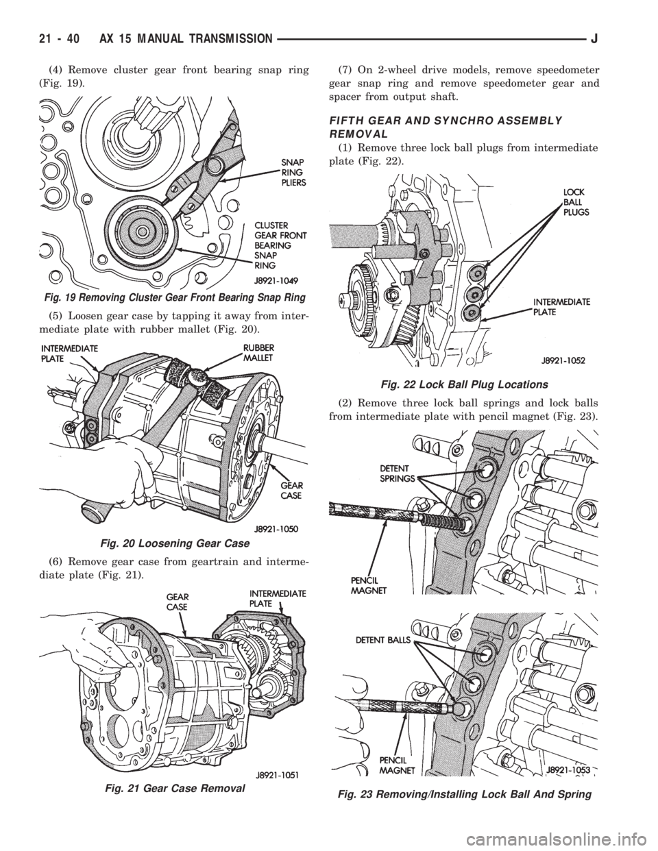
(4) Remove cluster gear front bearing snap ring
(Fig. 19).
(5) Loosen gear case by tapping it away from inter-
mediate plate with rubber mallet (Fig. 20).
(6) Remove gear case from geartrain and interme-
diate plate (Fig. 21).(7) On 2-wheel drive models, remove speedometer
gear snap ring and remove speedometer gear and
spacer from output shaft.
FIFTH GEAR AND SYNCHRO ASSEMBLY
REMOVAL
(1) Remove three lock ball plugs from intermediate
plate (Fig. 22).
(2) Remove three lock ball springs and lock balls
from intermediate plate with pencil magnet (Fig. 23).
Fig. 19 Removing Cluster Gear Front Bearing Snap Ring
Fig. 20 Loosening Gear Case
Fig. 21 Gear Case Removal
Fig. 22 Lock Ball Plug Locations
Fig. 23 Removing/Installing Lock Ball And Spring
21 - 40 AX 15 MANUAL TRANSMISSIONJ
Page 1152 of 1784
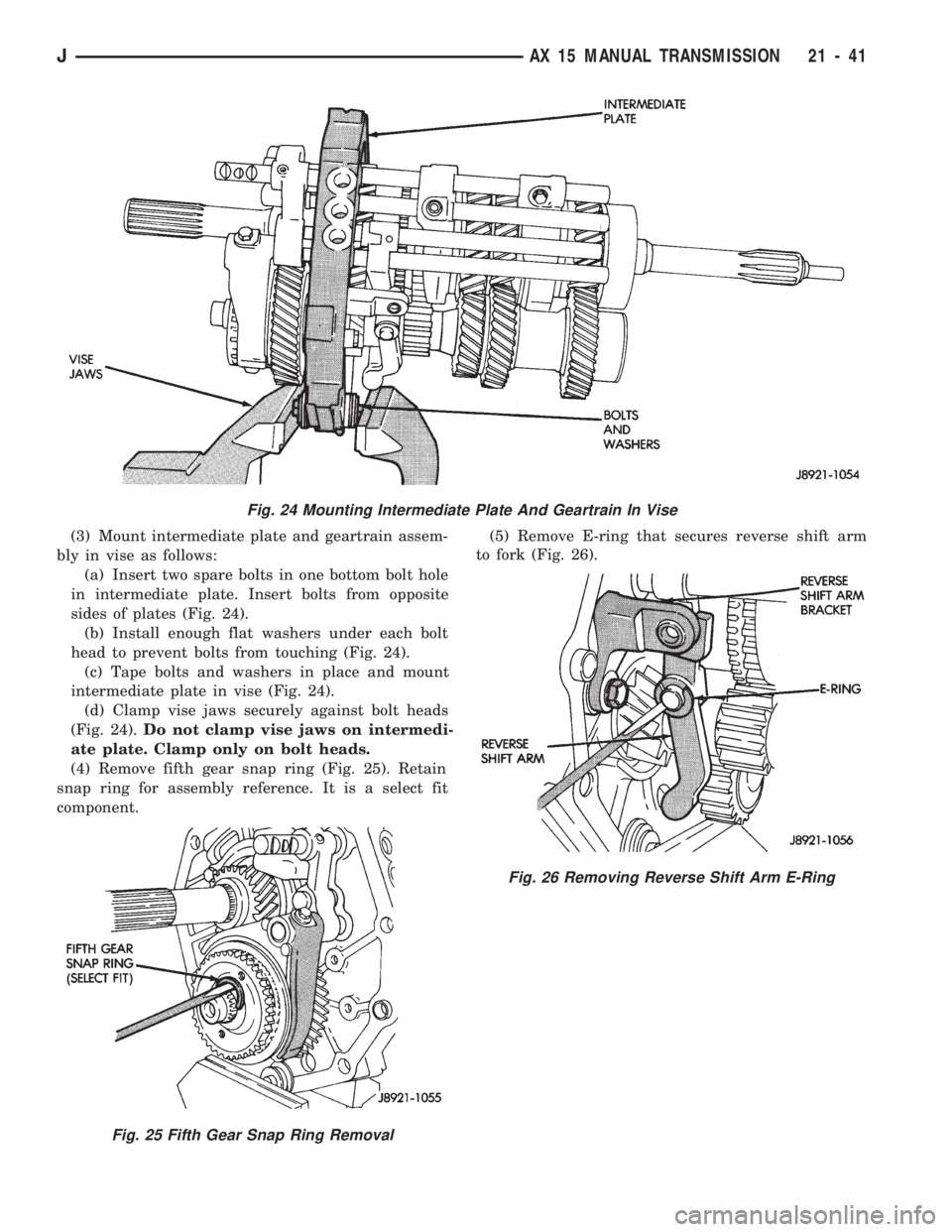
(3) Mount intermediate plate and geartrain assem-
bly in vise as follows:
(a) Insert two spare bolts in one bottom bolt hole
in intermediate plate. Insert bolts from opposite
sides of plates (Fig. 24).
(b) Install enough flat washers under each bolt
head to prevent bolts from touching (Fig. 24).
(c) Tape bolts and washers in place and mount
intermediate plate in vise (Fig. 24).
(d) Clamp vise jaws securely against bolt heads
(Fig. 24).Do not clamp vise jaws on intermedi-
ate plate. Clamp only on bolt heads.
(4) Remove fifth gear snap ring (Fig. 25). Retain
snap ring for assembly reference. It is a select fit
component.(5) Remove E-ring that secures reverse shift arm
to fork (Fig. 26).
Fig. 24 Mounting Intermediate Plate And Geartrain In Vise
Fig. 25 Fifth Gear Snap Ring Removal
Fig. 26 Removing Reverse Shift Arm E-Ring
JAX 15 MANUAL TRANSMISSION 21 - 41
Page 1153 of 1784
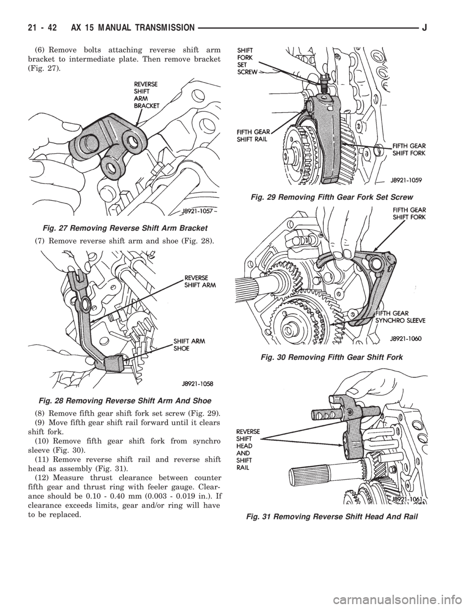
(6) Remove bolts attaching reverse shift arm
bracket to intermediate plate. Then remove bracket
(Fig. 27).
(7) Remove reverse shift arm and shoe (Fig. 28).
(8) Remove fifth gear shift fork set screw (Fig. 29).
(9) Move fifth gear shift rail forward until it clears
shift fork.
(10) Remove fifth gear shift fork from synchro
sleeve (Fig. 30).
(11) Remove reverse shift rail and reverse shift
head as assembly (Fig. 31).
(12) Measure thrust clearance between counter
fifth gear and thrust ring with feeler gauge. Clear-
ance should be 0.10 - 0.40 mm (0.003 - 0.019 in.). If
clearance exceeds limits, gear and/or ring will have
to be replaced.
Fig. 27 Removing Reverse Shift Arm Bracket
Fig. 28 Removing Reverse Shift Arm And Shoe
Fig. 29 Removing Fifth Gear Fork Set Screw
Fig. 30 Removing Fifth Gear Shift Fork
Fig. 31 Removing Reverse Shift Head And Rail
21 - 42 AX 15 MANUAL TRANSMISSIONJ
Page 1154 of 1784
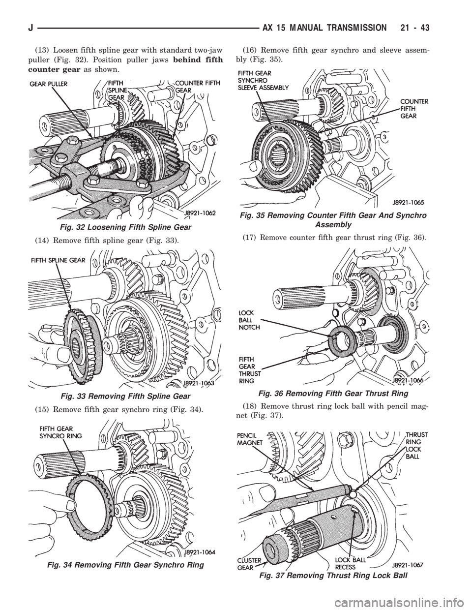
(13) Loosen fifth spline gear with standard two-jaw
puller (Fig. 32). Position puller jawsbehind fifth
counter gearas shown.
(14) Remove fifth spline gear (Fig. 33).
(15) Remove fifth gear synchro ring (Fig. 34).(16) Remove fifth gear synchro and sleeve assem-
bly (Fig. 35).
(17) Remove counter fifth gear thrust ring (Fig. 36).
(18) Remove thrust ring lock ball with pencil mag-
net (Fig. 37).
Fig. 37 Removing Thrust Ring Lock Ball
Fig. 32 Loosening Fifth Spline Gear
Fig. 33 Removing Fifth Spline Gear
Fig. 34 Removing Fifth Gear Synchro Ring
Fig. 35 Removing Counter Fifth Gear And Synchro
Assembly
Fig. 36 Removing Fifth Gear Thrust Ring
JAX 15 MANUAL TRANSMISSION 21 - 43
Page 1155 of 1784
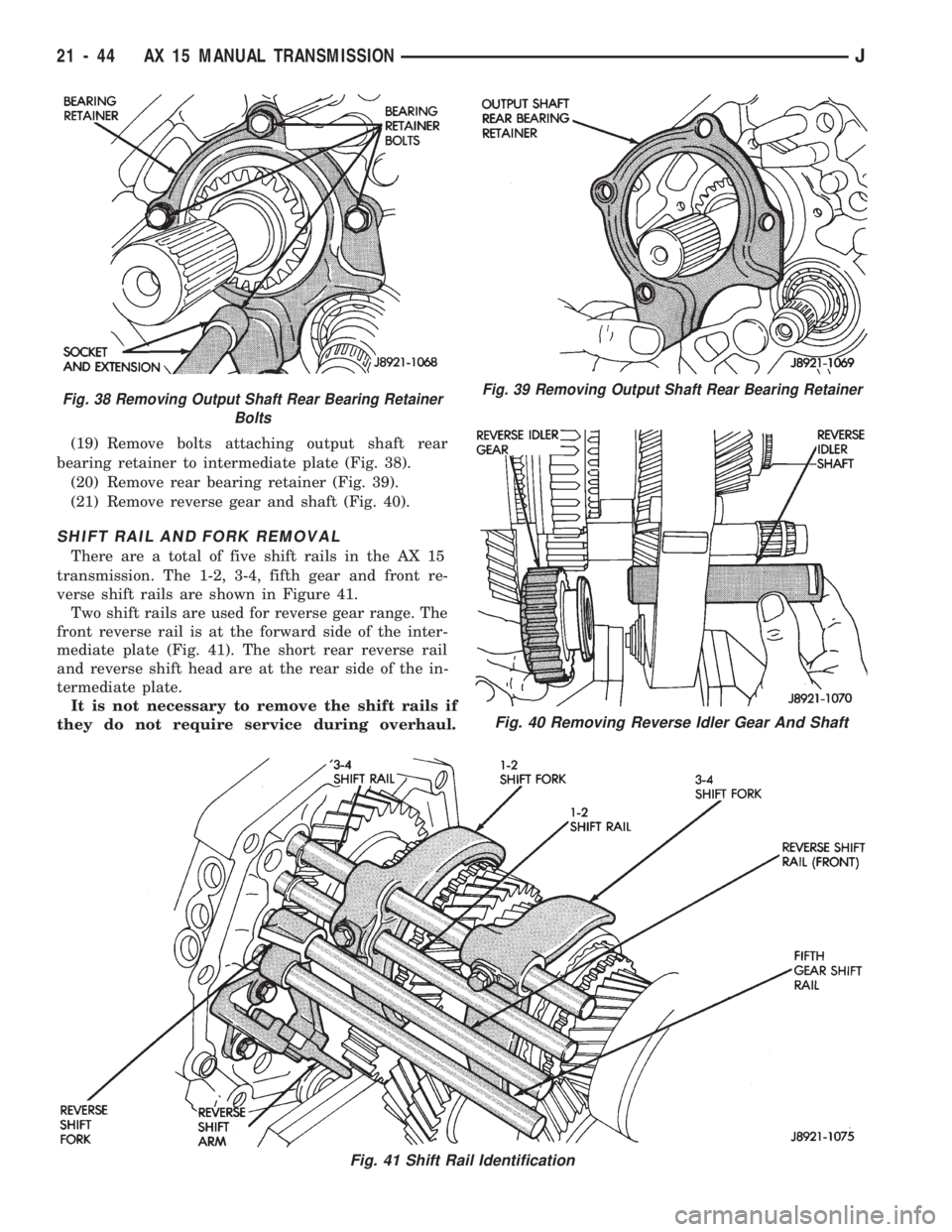
(19) Remove bolts attaching output shaft rear
bearing retainer to intermediate plate (Fig. 38).
(20) Remove rear bearing retainer (Fig. 39).
(21) Remove reverse gear and shaft (Fig. 40).
SHIFT RAIL AND FORK REMOVAL
There are a total of five shift rails in the AX 15
transmission. The 1-2, 3-4, fifth gear and front re-
verse shift rails are shown in Figure 41.
Two shift rails are used for reverse gear range. The
front reverse rail is at the forward side of the inter-
mediate plate (Fig. 41). The short rear reverse rail
and reverse shift head are at the rear side of the in-
termediate plate.
It is not necessary to remove the shift rails if
they do not require service during overhaul.
Fig. 38 Removing Output Shaft Rear Bearing Retainer
BoltsFig. 39 Removing Output Shaft Rear Bearing Retainer
Fig. 40 Removing Reverse Idler Gear And Shaft
Fig. 41 Shift Rail Identification
21 - 44 AX 15 MANUAL TRANSMISSIONJ
Page 1156 of 1784
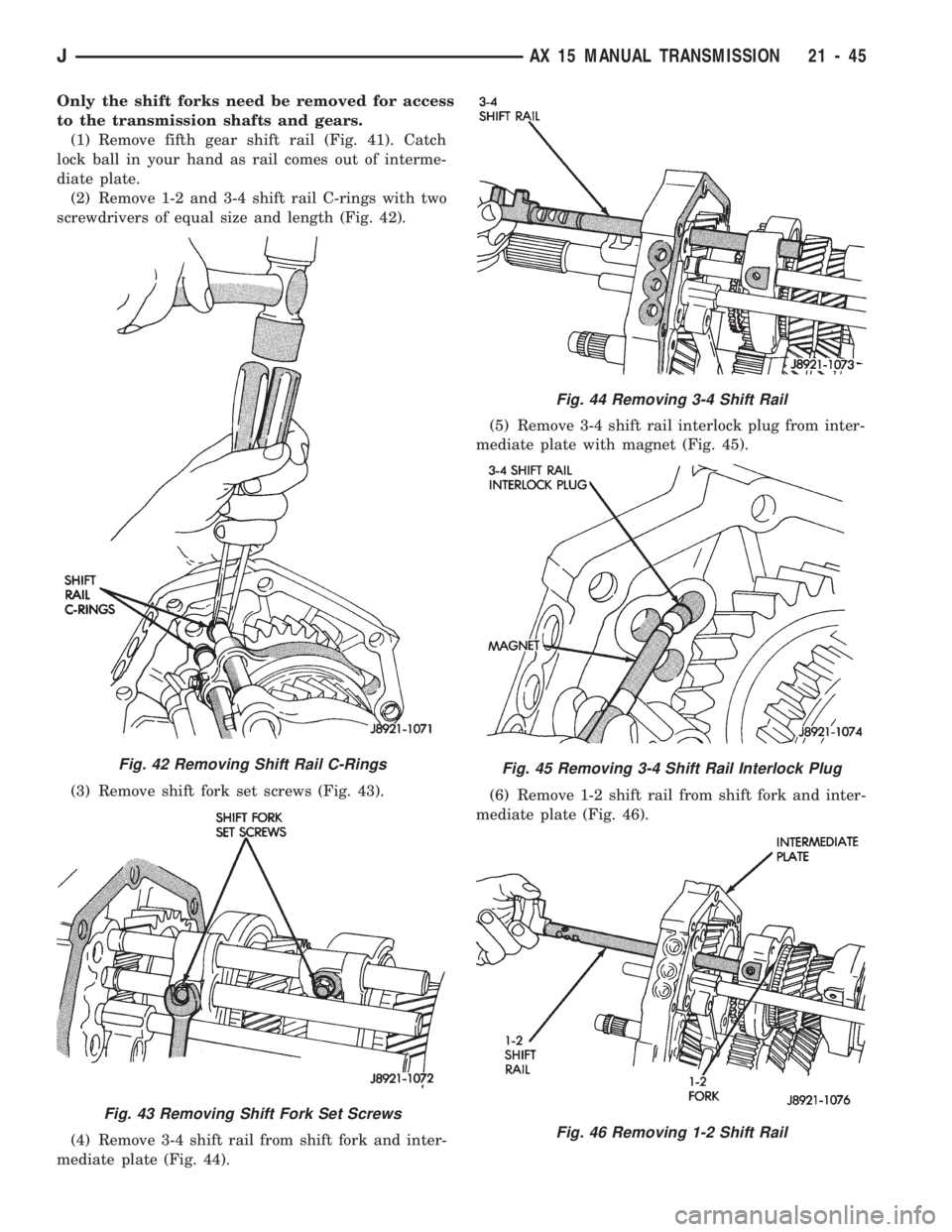
Only the shift forks need be removed for access
to the transmission shafts and gears.
(1) Remove fifth gear shift rail (Fig. 41). Catch
lock ball in your hand as rail comes out of interme-
diate plate.
(2) Remove 1-2 and 3-4 shift rail C-rings with two
screwdrivers of equal size and length (Fig. 42).
(3) Remove shift fork set screws (Fig. 43).
(4) Remove 3-4 shift rail from shift fork and inter-
mediate plate (Fig. 44).(5) Remove 3-4 shift rail interlock plug from inter-
mediate plate with magnet (Fig. 45).
(6) Remove 1-2 shift rail from shift fork and inter-
mediate plate (Fig. 46).
Fig. 42 Removing Shift Rail C-Rings
Fig. 43 Removing Shift Fork Set Screws
Fig. 44 Removing 3-4 Shift Rail
Fig. 45 Removing 3-4 Shift Rail Interlock Plug
Fig. 46 Removing 1-2 Shift Rail
JAX 15 MANUAL TRANSMISSION 21 - 45
Page 1157 of 1784
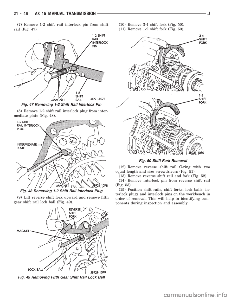
(7) Remove 1-2 shift rail interlock pin from shift
rail (Fig. 47).
(8) Remove 1-2 shift rail interlock plug from inter-
mediate plate (Fig. 48).
(9) Lift reverse shift fork upward and remove fifth
gear shift rail lock ball (Fig. 49).(10) Remove 3-4 shift fork (Fig. 50).
(11) Remove 1-2 shift fork (Fig. 50).
(12) Remove reverse shift rail C-ring with two
equal length and size screwdrivers (Fig. 51).
(13) Remove reverse shift rail and fork (Fig. 52).
(14) Remove interlock pin from reverse shift rail
(Fig. 53).
(15) Position shift rails, shift forks, lock balls, in-
terlock plugs and interlock pins on the workbench in
order of removal. This will help in identifying com-
ponents during inspection and assembly.
Fig. 47 Removing 1-2 Shift Rail Interlock Pin
Fig. 48 Removing 1-2 Shift Rail Interlock Plug
Fig. 49 Removing Fifth Gear Shift Rail Lock Ball
Fig. 50 Shift Fork Removal
21 - 46 AX 15 MANUAL TRANSMISSIONJ
Page 1158 of 1784
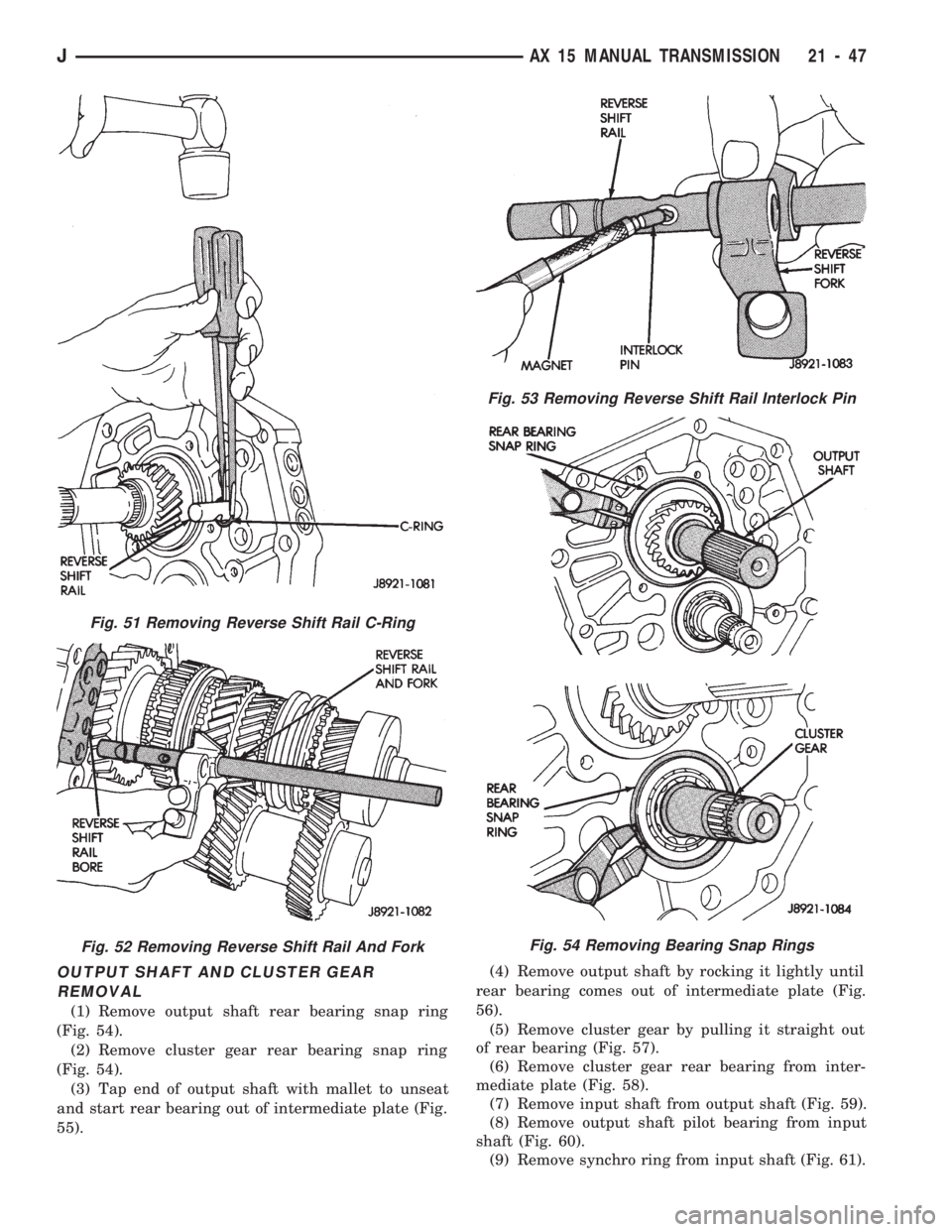
OUTPUT SHAFT AND CLUSTER GEAR
REMOVAL
(1) Remove output shaft rear bearing snap ring
(Fig. 54).
(2) Remove cluster gear rear bearing snap ring
(Fig. 54).
(3) Tap end of output shaft with mallet to unseat
and start rear bearing out of intermediate plate (Fig.
55).(4) Remove output shaft by rocking it lightly until
rear bearing comes out of intermediate plate (Fig.
56).
(5) Remove cluster gear by pulling it straight out
of rear bearing (Fig. 57).
(6) Remove cluster gear rear bearing from inter-
mediate plate (Fig. 58).
(7) Remove input shaft from output shaft (Fig. 59).
(8) Remove output shaft pilot bearing from input
shaft (Fig. 60).
(9) Remove synchro ring from input shaft (Fig. 61).
Fig. 51 Removing Reverse Shift Rail C-Ring
Fig. 52 Removing Reverse Shift Rail And Fork
Fig. 53 Removing Reverse Shift Rail Interlock Pin
Fig. 54 Removing Bearing Snap Rings
JAX 15 MANUAL TRANSMISSION 21 - 47
Page 1159 of 1784
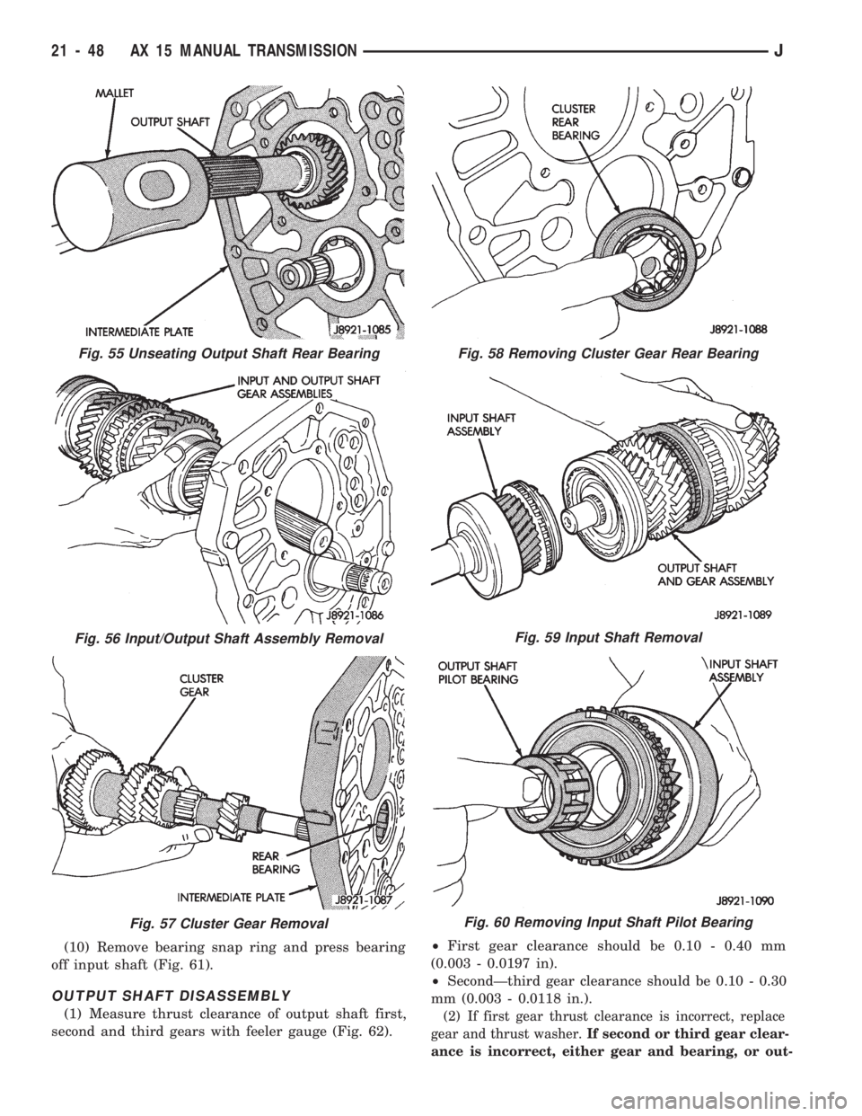
(10) Remove bearing snap ring and press bearing
off input shaft (Fig. 61).
OUTPUT SHAFT DISASSEMBLY
(1) Measure thrust clearance of output shaft first,
second and third gears with feeler gauge (Fig. 62).²First gear clearance should be 0.10 - 0.40 mm
(0.003 - 0.0197 in).
²SecondÐthird gear clearance should be 0.10 - 0.30
mm (0.003 - 0.0118 in.).(2) If first gear thrust clearance is incorrect, replace
gear and thrust washer.If second or third gear clear-
ance is incorrect, either gear and bearing, or out-
Fig. 55 Unseating Output Shaft Rear Bearing
Fig. 56 Input/Output Shaft Assembly Removal
Fig. 57 Cluster Gear Removal
Fig. 58 Removing Cluster Gear Rear Bearing
Fig. 59 Input Shaft Removal
Fig. 60 Removing Input Shaft Pilot Bearing
21 - 48 AX 15 MANUAL TRANSMISSIONJ
Page 1160 of 1784
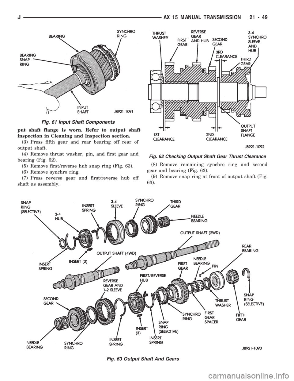
put shaft flange is worn. Refer to output shaft
inspection in Cleaning and Inspection section.
(3) Press fifth gear and rear bearing off rear of
output shaft.
(4) Remove thrust washer, pin, and first gear and
bearing (Fig. 62).
(5) Remove first/reverse hub snap ring (Fig. 63).
(6) Remove synchro ring.
(7) Press reverse gear and first/reverse hub off
shaft as assembly.(8) Remove remaining synchro ring and second
gear and bearing (Fig. 63).
(9) Remove snap ring at front of output shaft (Fig.
63).
Fig. 62 Checking Output Shaft Gear Thrust Clearance
Fig. 63 Output Shaft And Gears
Fig. 61 Input Shaft Components
JAX 15 MANUAL TRANSMISSION 21 - 49