JEEP CHEROKEE 1994 Service Repair Manual
Manufacturer: JEEP, Model Year: 1994, Model line: CHEROKEE, Model: JEEP CHEROKEE 1994Pages: 1784, PDF Size: 77.09 MB
Page 1601 of 1784
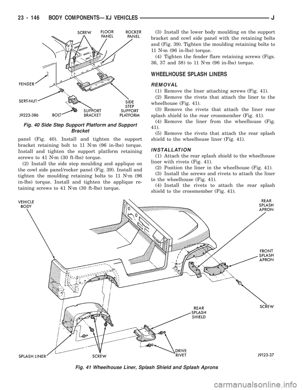
panel (Fig. 40). Install and tighten the support
bracket retaining bolt to 11 Nzm (96 in-lbs) torque.
Install and tighten the support platform retaining
screws to 41 Nzm (30 ft-lbs) torque.
(2) Install the side step moulding and applique on
the cowl side panel/rocker panel (Fig. 39). Install and
tighten the moulding retaining bolts to 11 Nzm (96
in-lbs) torque. Install and tighten the applique re-
taining screws to 41 Nzm (30 ft-lbs) torque.(3) Install the lower body moulding on the support
bracket and cowl side panel with the retaining bolts
and (Fig. 39). Tighten the moulding retaining bolts to
11 Nzm (96 in-lbs) torque.
(4) Tighten the fender flare retaining screws (Figs.
36, 37 and 38) to 11 Nzm (96 in-lbs) torque.
WHEELHOUSE SPLASH LINERS
REMOVAL
(1) Remove the liner attaching screws (Fig. 41).
(2) Remove the rivets that attach the liner to the
wheelhouse (Fig. 41).
(3) Remove the rivets that attach the liner rear
splash shield to the rear crossmember (Fig. 41).
(4) Remove the liner from the wheelhouse (Fig.
41).
(5) Remove the rivets that attach the rear splash
shield to the wheelhouse liner (Fig. 41).
INSTALLATION
(1) Attach the rear splash shield to the wheelhouse
liner with rivets (Fig. 41).
(2) Position the liner in the wheelhouse (Fig. 41).
(3) Install the screws and rivets to attach the liner
to the wheelhouse (Fig. 41).
(4) Install the rivets to attach the rear splash
shield to the crossmember (Fig. 41).
Fig. 41 Wheelhouse Liner, Splash Shield and Splash Aprons
Fig. 40 Side Step Support Platform and Support
Bracket
23 - 146 BODY COMPONENTSÐXJ VEHICLESJ
Page 1602 of 1784
FENDER SPLASH APRONS
REMOVAL
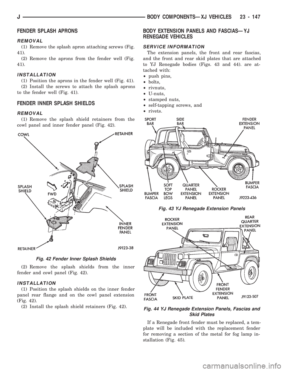
(1) Remove the splash apron attaching screws (Fig.
41).
(2) Remove the aprons from the fender well (Fig.
41).
INSTALLATION
(1) Position the aprons in the fender well (Fig. 41).
(2) Install the screws to attach the splash aprons
to the fender well (Fig. 41).
FENDER INNER SPLASH SHIELDS
REMOVAL
(1) Remove the splash shield retainers from the
cowl panel and inner fender panel (Fig. 42).
(2) Remove the splash shields from the inner
fender and cowl panel (Fig. 42).
INSTALLATION
(1) Position the splash shields on the inner fender
panel rear flange and on the cowl panel extension
(Fig. 42).
(2) Install the splash shield retainers (Fig. 42).
BODY EXTENSION PANELS AND FASCIASÐYJ
RENEGADE VEHICLES
SERVICE INFORMATION
The extension panels, the front and rear fascias,
and the front and rear skid plates that are attached
to YJ Renegade bodies (Figs. 43 and 44). are at-
tached with:
²push pins,
²bolts,
²rivnuts,
²U-nuts,
²stamped nuts,
²self-tapping screws, and
²rivets.
If a Renegade front fender must be replaced, a tem-
plate will be included with the replacement fender
for removing a section of the metal for fog lamp in-
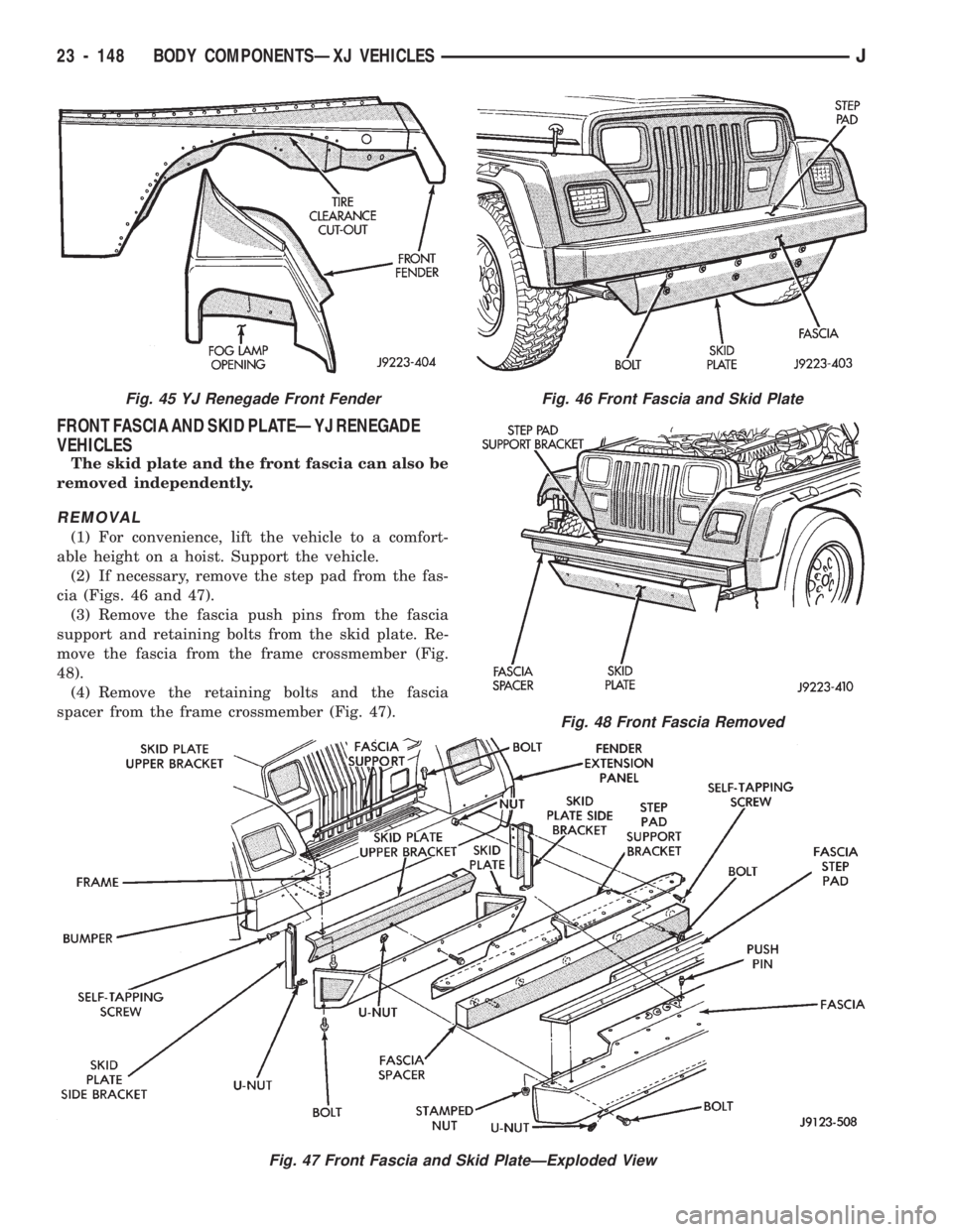
stallation (Fig. 45).
Fig. 42 Fender Inner Splash Shields
Fig. 43 YJ Renegade Extension Panels
Fig. 44 YJ Renegade Extension Panels, Fascias and
Skid Plates
JBODY COMPONENTSÐXJ VEHICLES 23 - 147
Page 1603 of 1784
FRONT FASCIA AND SKID PLATEÐYJ RENEGADE
VEHICLES
The skid plate and the front fascia can also be
removed independently.
REMOVAL
(1) For convenience, lift the vehicle to a comfort-
able height on a hoist. Support the vehicle.
(2) If necessary, remove the step pad from the fas-
cia (Figs. 46 and 47).
(3) Remove the fascia push pins from the fascia
support and retaining bolts from the skid plate. Re-
move the fascia from the frame crossmember (Fig.
48).
(4) Remove the retaining bolts and the fascia
spacer from the frame crossmember (Fig. 47).
Fig. 46 Front Fascia and Skid Plate
Fig. 47 Front Fascia and Skid PlateÐExploded View
Fig. 48 Front Fascia Removed
Fig. 45 YJ Renegade Front Fender
23 - 148 BODY COMPONENTSÐXJ VEHICLESJ
Page 1604 of 1784
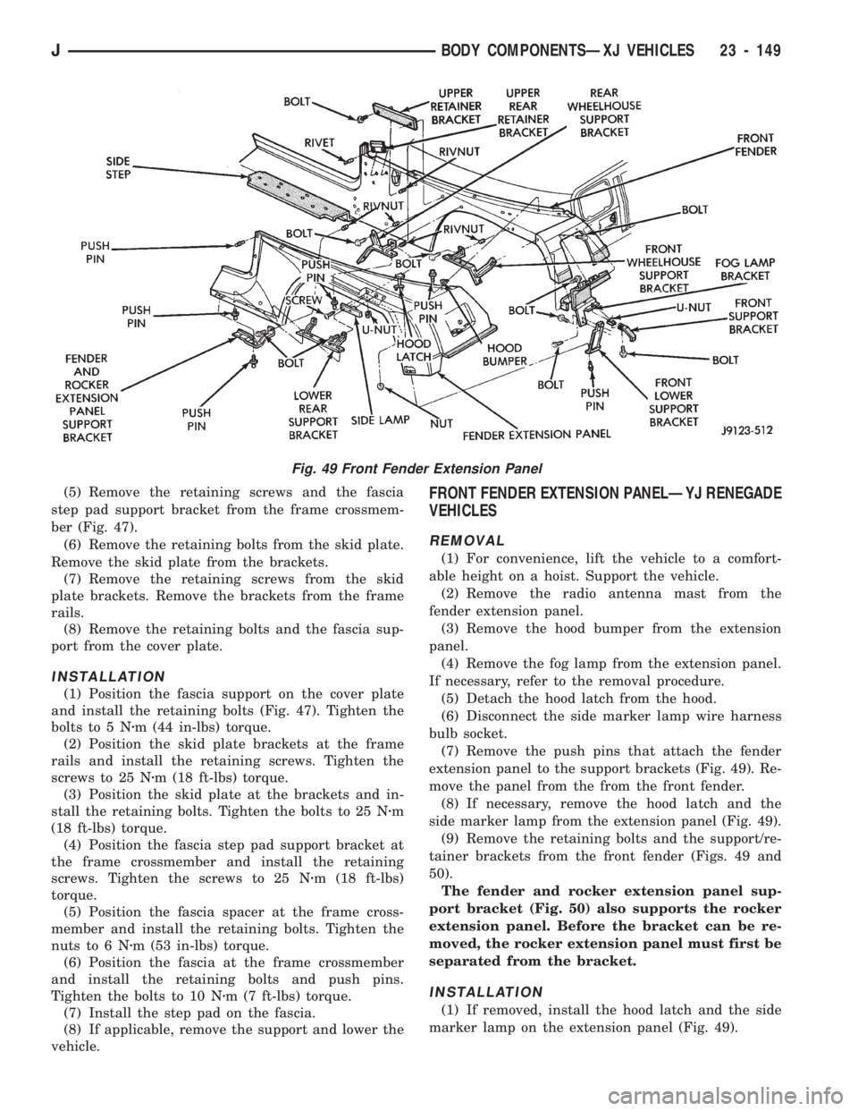
(5) Remove the retaining screws and the fascia
step pad support bracket from the frame crossmem-
ber (Fig. 47).
(6) Remove the retaining bolts from the skid plate.
Remove the skid plate from the brackets.
(7) Remove the retaining screws from the skid
plate brackets. Remove the brackets from the frame
rails.
(8) Remove the retaining bolts and the fascia sup-
port from the cover plate.
INSTALLATION
(1) Position the fascia support on the cover plate
and install the retaining bolts (Fig. 47). Tighten the
bolts to 5 Nzm (44 in-lbs) torque.
(2) Position the skid plate brackets at the frame
rails and install the retaining screws. Tighten the
screws to 25 Nzm (18 ft-lbs) torque.
(3) Position the skid plate at the brackets and in-
stall the retaining bolts. Tighten the bolts to 25 Nzm
(18 ft-lbs) torque.
(4) Position the fascia step pad support bracket at
the frame crossmember and install the retaining
screws. Tighten the screws to 25 Nzm (18 ft-lbs)
torque.
(5) Position the fascia spacer at the frame cross-
member and install the retaining bolts. Tighten the
nuts to 6 Nzm (53 in-lbs) torque.
(6) Position the fascia at the frame crossmember
and install the retaining bolts and push pins.
Tighten the bolts to 10 Nzm (7 ft-lbs) torque.
(7) Install the step pad on the fascia.
(8) If applicable, remove the support and lower the
vehicle.
FRONT FENDER EXTENSION PANELÐYJ RENEGADE
VEHICLES
REMOVAL
(1) For convenience, lift the vehicle to a comfort-
able height on a hoist. Support the vehicle.
(2) Remove the radio antenna mast from the
fender extension panel.
(3) Remove the hood bumper from the extension
panel.
(4) Remove the fog lamp from the extension panel.
If necessary, refer to the removal procedure.
(5) Detach the hood latch from the hood.
(6) Disconnect the side marker lamp wire harness
bulb socket.
(7) Remove the push pins that attach the fender
extension panel to the support brackets (Fig. 49). Re-
move the panel from the from the front fender.
(8) If necessary, remove the hood latch and the
side marker lamp from the extension panel (Fig. 49).
(9) Remove the retaining bolts and the support/re-
tainer brackets from the front fender (Figs. 49 and
50).
The fender and rocker extension panel sup-
port bracket (Fig. 50) also supports the rocker
extension panel. Before the bracket can be re-
moved, the rocker extension panel must first be
separated from the bracket.
INSTALLATION
(1) If removed, install the hood latch and the side
marker lamp on the extension panel (Fig. 49).
Fig. 49 Front Fender Extension Panel
JBODY COMPONENTSÐXJ VEHICLES 23 - 149
Page 1605 of 1784
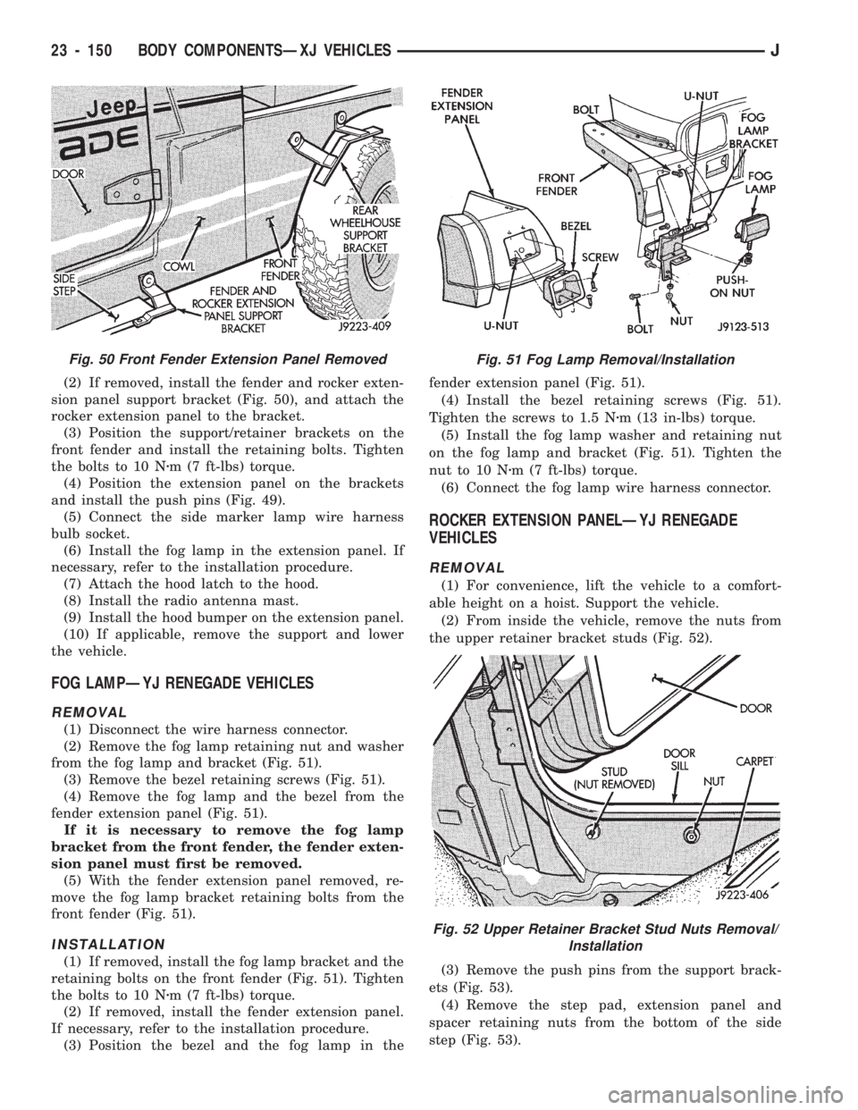
(2) If removed, install the fender and rocker exten-
sion panel support bracket (Fig. 50), and attach the
rocker extension panel to the bracket.
(3) Position the support/retainer brackets on the
front fender and install the retaining bolts. Tighten
the bolts to 10 Nzm (7 ft-lbs) torque.
(4) Position the extension panel on the brackets
and install the push pins (Fig. 49).
(5) Connect the side marker lamp wire harness
bulb socket.
(6) Install the fog lamp in the extension panel. If
necessary, refer to the installation procedure.
(7) Attach the hood latch to the hood.
(8) Install the radio antenna mast.
(9) Install the hood bumper on the extension panel.
(10) If applicable, remove the support and lower
the vehicle.
FOG LAMPÐYJ RENEGADE VEHICLES
REMOVAL
(1) Disconnect the wire harness connector.
(2) Remove the fog lamp retaining nut and washer
from the fog lamp and bracket (Fig. 51).
(3) Remove the bezel retaining screws (Fig. 51).
(4) Remove the fog lamp and the bezel from the
fender extension panel (Fig. 51).
If it is necessary to remove the fog lamp
bracket from the front fender, the fender exten-
sion panel must first be removed.
(5) With the fender extension panel removed, re-
move the fog lamp bracket retaining bolts from the
front fender (Fig. 51).
INSTALLATION
(1) If removed, install the fog lamp bracket and the
retaining bolts on the front fender (Fig. 51). Tighten
the bolts to 10 Nzm (7 ft-lbs) torque.
(2) If removed, install the fender extension panel.
If necessary, refer to the installation procedure.
(3) Position the bezel and the fog lamp in thefender extension panel (Fig. 51).
(4) Install the bezel retaining screws (Fig. 51).
Tighten the screws to 1.5 Nzm (13 in-lbs) torque.
(5) Install the fog lamp washer and retaining nut
on the fog lamp and bracket (Fig. 51). Tighten the
nut to 10 Nzm (7 ft-lbs) torque.
(6) Connect the fog lamp wire harness connector.
ROCKER EXTENSION PANELÐYJ RENEGADE
VEHICLES
REMOVAL
(1) For convenience, lift the vehicle to a comfort-
able height on a hoist. Support the vehicle.
(2) From inside the vehicle, remove the nuts from
the upper retainer bracket studs (Fig. 52).
(3) Remove the push pins from the support brack-
ets (Fig. 53).
(4) Remove the step pad, extension panel and
spacer retaining nuts from the bottom of the side
step (Fig. 53).
Fig. 50 Front Fender Extension Panel RemovedFig. 51 Fog Lamp Removal/Installation
Fig. 52 Upper Retainer Bracket Stud Nuts Removal/
Installation
23 - 150 BODY COMPONENTSÐXJ VEHICLESJ
Page 1606 of 1784
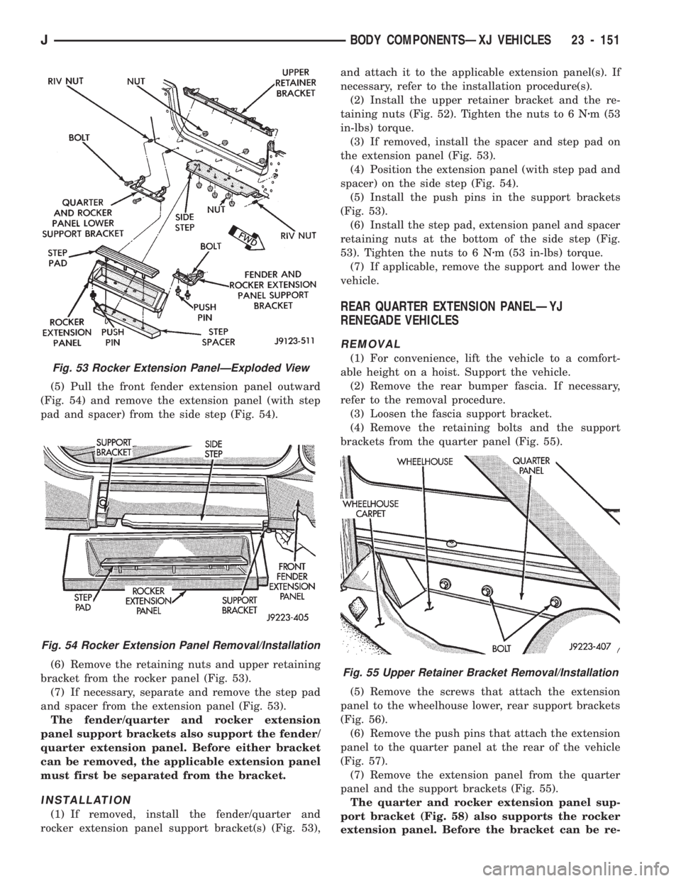
(5) Pull the front fender extension panel outward
(Fig. 54) and remove the extension panel (with step
pad and spacer) from the side step (Fig. 54).
(6) Remove the retaining nuts and upper retaining
bracket from the rocker panel (Fig. 53).
(7) If necessary, separate and remove the step pad
and spacer from the extension panel (Fig. 53).
The fender/quarter and rocker extension
panel support brackets also support the fender/
quarter extension panel. Before either bracket
can be removed, the applicable extension panel
must first be separated from the bracket.
INSTALLATION
(1) If removed, install the fender/quarter and
rocker extension panel support bracket(s) (Fig. 53),and attach it to the applicable extension panel(s). If
necessary, refer to the installation procedure(s).
(2) Install the upper retainer bracket and the re-
taining nuts (Fig. 52). Tighten the nuts to 6 Nzm (53
in-lbs) torque.
(3) If removed, install the spacer and step pad on
the extension panel (Fig. 53).
(4) Position the extension panel (with step pad and
spacer) on the side step (Fig. 54).
(5) Install the push pins in the support brackets
(Fig. 53).
(6) Install the step pad, extension panel and spacer
retaining nuts at the bottom of the side step (Fig.
53). Tighten the nuts to 6 Nzm (53 in-lbs) torque.
(7) If applicable, remove the support and lower the
vehicle.
REAR QUARTER EXTENSION PANELÐYJ
RENEGADE VEHICLES
REMOVAL
(1) For convenience, lift the vehicle to a comfort-
able height on a hoist. Support the vehicle.
(2) Remove the rear bumper fascia. If necessary,
refer to the removal procedure.
(3) Loosen the fascia support bracket.
(4) Remove the retaining bolts and the support
brackets from the quarter panel (Fig. 55).
(5) Remove the screws that attach the extension
panel to the wheelhouse lower, rear support brackets
(Fig. 56).
(6) Remove the push pins that attach the extension
panel to the quarter panel at the rear of the vehicle
(Fig. 57).
(7) Remove the extension panel from the quarter
panel and the support brackets (Fig. 55).
The quarter and rocker extension panel sup-
port bracket (Fig. 58) also supports the rocker
extension panel. Before the bracket can be re-
Fig. 55 Upper Retainer Bracket Removal/Installation
Fig. 53 Rocker Extension PanelÐExploded View
Fig. 54 Rocker Extension Panel Removal/Installation
JBODY COMPONENTSÐXJ VEHICLES 23 - 151
Page 1607 of 1784
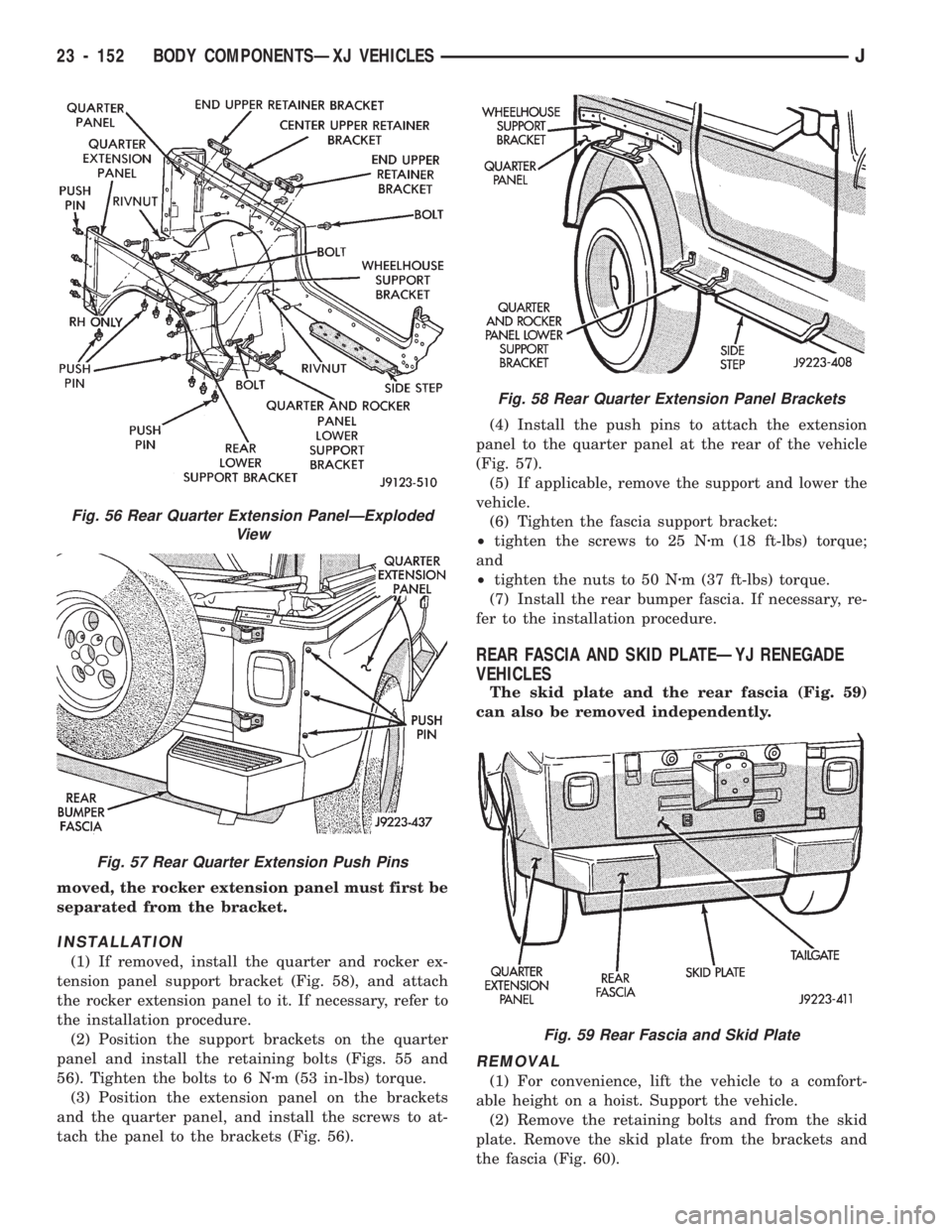
moved, the rocker extension panel must first be
separated from the bracket.
INSTALLATION
(1) If removed, install the quarter and rocker ex-
tension panel support bracket (Fig. 58), and attach
the rocker extension panel to it. If necessary, refer to
the installation procedure.
(2) Position the support brackets on the quarter
panel and install the retaining bolts (Figs. 55 and
56). Tighten the bolts to 6 Nzm (53 in-lbs) torque.
(3) Position the extension panel on the brackets
and the quarter panel, and install the screws to at-
tach the panel to the brackets (Fig. 56).(4) Install the push pins to attach the extension
panel to the quarter panel at the rear of the vehicle
(Fig. 57).
(5) If applicable, remove the support and lower the
vehicle.
(6) Tighten the fascia support bracket:
²tighten the screws to 25 Nzm (18 ft-lbs) torque;
and
²tighten the nuts to 50 Nzm (37 ft-lbs) torque.
(7) Install the rear bumper fascia. If necessary, re-
fer to the installation procedure.
REAR FASCIA AND SKID PLATEÐYJ RENEGADE
VEHICLES
The skid plate and the rear fascia (Fig. 59)
can also be removed independently.
REMOVAL
(1) For convenience, lift the vehicle to a comfort-
able height on a hoist. Support the vehicle.
(2) Remove the retaining bolts and from the skid
plate. Remove the skid plate from the brackets and
the fascia (Fig. 60).
Fig. 56 Rear Quarter Extension PanelÐExploded
View
Fig. 57 Rear Quarter Extension Push Pins
Fig. 58 Rear Quarter Extension Panel Brackets
Fig. 59 Rear Fascia and Skid Plate
23 - 152 BODY COMPONENTSÐXJ VEHICLESJ
Page 1608 of 1784
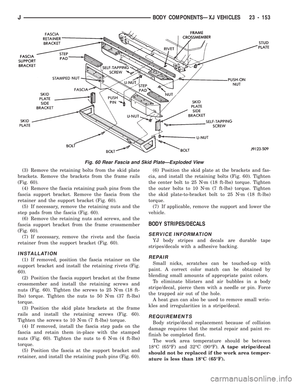
(3) Remove the retaining bolts from the skid plate
brackets. Remove the brackets from the frame rails
(Fig. 60).
(4) Remove the fascia retaining push pins from the
fascia support bracket. Remove the fascia from the
retainer and the support bracket (Fig. 60).
(5) If necessary, remove the retaining nuts and the
step pads from the fascia (Fig. 60).
(6) Remove the retaining nuts and screws, and the
fascia support bracket from the frame crossmember
(Fig. 60).
(7) If necessary, remove the rivets and the fascia
retainer from the support bracket (Fig. 60).
INSTALLATION
(1) If removed, position the fascia retainer on the
support bracket and install the retaining rivets (Fig.
60).
(2) Position the fascia support bracket at the frame
crossmember and install the retaining screws and
nuts (Fig. 60). Tighten the screws to 25 Nzm (18 ft-
lbs) torque. Tighten the nuts to 50 Nzm (37 ft-lbs)
torque.
(3) Position the skid plate brackets at the frame
rails and install the retaining screws (Fig. 60).
Tighten the screws to 10 Nzm (7 ft-lbs) torque.
(4) If removed, install the fascia step pads on the
fascia and retain them in-place with the stamped
nuts (Fig. 60). Tighten the nuts to 6 Nzm (4 ft-lbs)
torque.
(5) Position the fascia at the support bracket and
retainer, and install the retaining push pins (Fig. 60).(6) Position the skid plate at the brackets and fas-
cia, and install the retaining bolts (Fig. 60). Tighten
the center bolt to 25 Nzm (18 ft-lbs) torque. Tighten
the outer bolts to 10 Nzm (7 ft-lbs) torque. Tighten
the skid plate-to-bracket bolt to 25 Nzm (18 ft-lbs)
torque.
(7) If applicable, remove the support and lower the
vehicle.
BODY STRIPES/DECALS
SERVICE INFORMATION
YJ body stripes and decals are durable tape
stripes/decals with a adhesive backing.
REPAIR
Small nicks, scratches can be touched-up with
paint. A correct color match can be obtained by
blending small amounts of appropriate paint colors.
To eliminate blisters and air bubbles in a body
stripe/decal, pierce them with a needle or pin. Force
the trapped air out of the hole.
A heat gun can also be used to remove small wrin-
kles and irregularities in a stripe/decal.
REQUIREMENTS
Body stripe/decal replacement because of collision
damage requires that the metal repair and paint re-
finish be completed first.
The work area temperature should be between
18ÉC (65ÉF) and 32ÉC (90ÉF).A tape stripe/decal
should not be replaced if the work area temper-
ature is less than 18ÉC (65ÉF).
Fig. 60 Rear Fascia and Skid PlateÐExploded View
JBODY COMPONENTSÐXJ VEHICLES 23 - 153
Page 1609 of 1784
The following equipment and material are neces-
sary for body stripe/decal removal and installation:
²a commercial tape stripe/decal removal solution;
²a commercial adhesive removal solution;
²liquid dish detergent (for the wetting solution);
²a mixture of wetting solution;
²a commercial wax and silicone removal solution;
²isopropyl (rubbing) alcohol;
²a small squeegee (plastic or hard rubber);
²a water bucket and sponge;
²clean wiping rags or paper towels;
²a heat gun (or infra-red heat bulb);
²a wax pencil;
²a sharp knife, single edge razor blade or X-acto
knife;
²a pair of scissors; and
²a needle or pin.
A wetting solution assures a better bond between
the painted surface of the body and the tape stripe/
decal. Prepare a supply of wetting solution by mixing
two or three teaspoons of dish detergent with 1 gal-
lon of water.Do not use soap.
Too much detergent will reduce the effective-
ness of the mixture.
REMOVAL
The key to successful tape stripe/decal re-
moval is to apply heat to area and slowly peel
stripe/decal from panel.
(1) Clean the repaired surface, adjacent panels and
door openings as necessary.
(2) Start at one end of the tape stripe/decal and
apply heat with a heat gun. Slowly peel the stripe/
decal from the panel by pulling it back.Do not pull
the tape stripe/decal outward from the panel.
WARNING: USE THE TAPE STRIPE/DECAL RE-
MOVAL SOLUTION IN A WELL-VENTILATED AREA
ONLY.
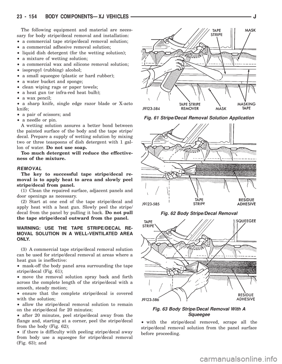
(3) A commercial tape stripe/decal removal solution
can be used for stripe/decal removal at areas where a
heat gun is ineffective:
²mask-off the body panel area surrounding the tape
stripe/decal (Fig. 61);
²move the removal solution spray back and forth
across the complete length of the stripe/decal with a
smooth, steady motion;
²ensure that the complete stripe/decal is covered
with the solution;
²allow the stripe/decal removal solution to remain
on the stripe/decal for 20 minutes;
²after 20 minutes, peel stripe/decal away from the
flange and, starting at a corner, peel the stripe/decal
from the body (Fig. 62);
²if there is difficulty with peeling stripe/decal away
from body use a squeegee for stripe/decal removal
(Fig. 63); and²with the stripe/decal removed, scrape all the
stripe/decal removal solution from the panel surface
before proceeding.
Fig. 61 Stripe/Decal Removal Solution Application
Fig. 62 Body Stripe/Decal Removal
Fig. 63 Body Stripe/Decal Removal With A
Squeegee
23 - 154 BODY COMPONENTSÐXJ VEHICLESJ
Page 1610 of 1784
WARNING: USE THE ADHESIVE REMOVAL SOLU-
TION IN A WELL-VENTILATED AREA ONLY.
(4) After the stripe/decal is removed, remove any
adhesive remaining on body with a removal solution.
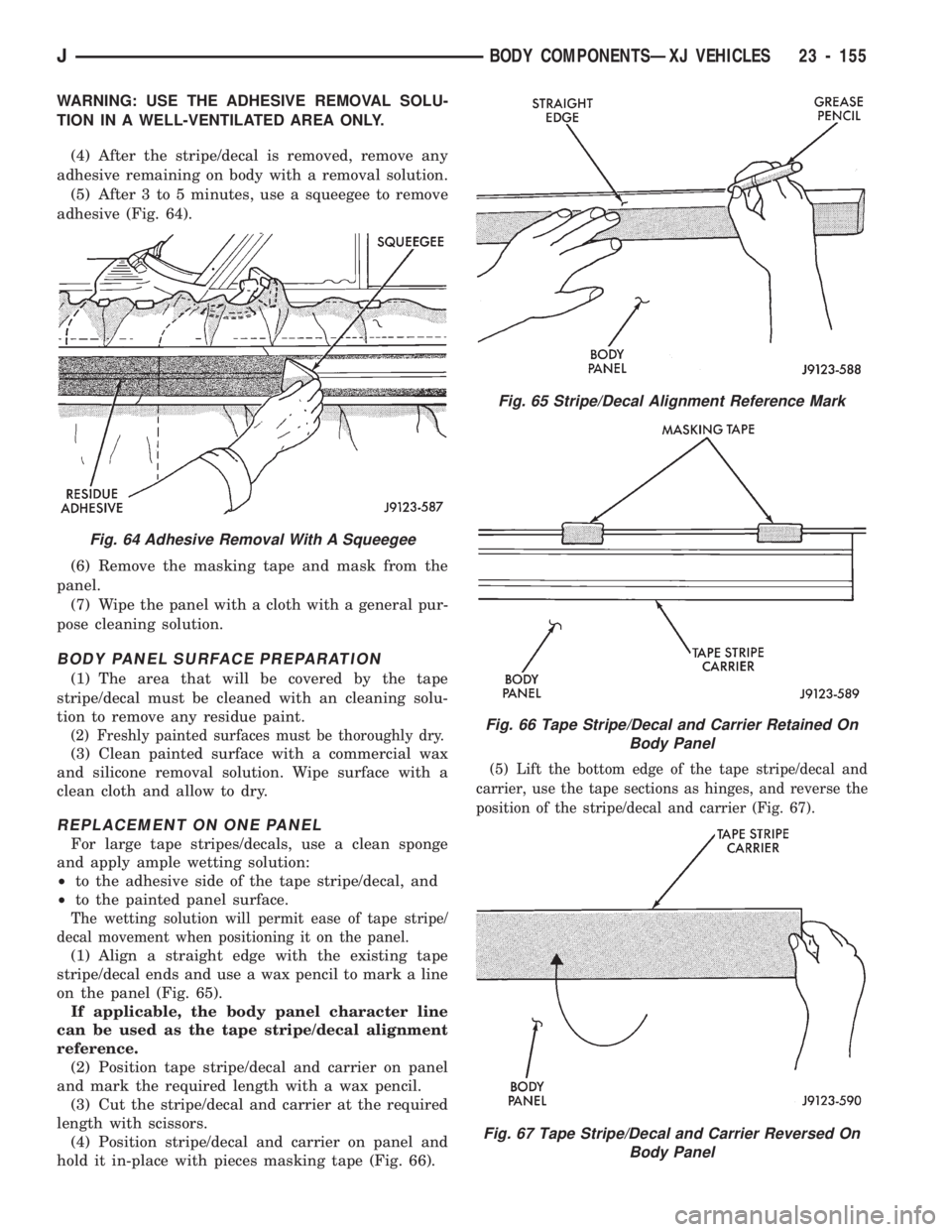
(5) After 3 to 5 minutes, use a squeegee to remove
adhesive (Fig. 64).
(6) Remove the masking tape and mask from the
panel.
(7) Wipe the panel with a cloth with a general pur-
pose cleaning solution.
BODY PANEL SURFACE PREPARATION
(1) The area that will be covered by the tape
stripe/decal must be cleaned with an cleaning solu-
tion to remove any residue paint.
(2) Freshly painted surfaces must be thoroughly dry.
(3) Clean painted surface with a commercial wax
and silicone removal solution. Wipe surface with a
clean cloth and allow to dry.
REPLACEMENT ON ONE PANEL
For large tape stripes/decals, use a clean sponge
and apply ample wetting solution:
²to the adhesive side of the tape stripe/decal, and
²to the painted panel surface.
The wetting solution will permit ease of tape stripe/
decal movement when positioning it on the panel.
(1) Align a straight edge with the existing tape
stripe/decal ends and use a wax pencil to mark a line
on the panel (Fig. 65).
If applicable, the body panel character line
can be used as the tape stripe/decal alignment
reference.
(2) Position tape stripe/decal and carrier on panel
and mark the required length with a wax pencil.
(3) Cut the stripe/decal and carrier at the required
length with scissors.
(4) Position stripe/decal and carrier on panel and
hold it in-place with pieces masking tape (Fig. 66).
(5) Lift the bottom edge of the tape stripe/decal and
carrier, use the tape sections as hinges, and reverse the
position of the stripe/decal and carrier (Fig. 67).
Fig. 65 Stripe/Decal Alignment Reference Mark
Fig. 66 Tape Stripe/Decal and Carrier Retained On
Body Panel
Fig. 67 Tape Stripe/Decal and Carrier Reversed On
Body Panel
Fig. 64 Adhesive Removal With A Squeegee
JBODY COMPONENTSÐXJ VEHICLES 23 - 155