JEEP CHEROKEE 1994 Service Repair Manual
Manufacturer: JEEP, Model Year: 1994, Model line: CHEROKEE, Model: JEEP CHEROKEE 1994Pages: 1784, PDF Size: 77.09 MB
Page 1611 of 1784
CAUTION: Always remove the carrier from the tape
stripe/decal, never remove the tape stripe/decal
from the carrier.
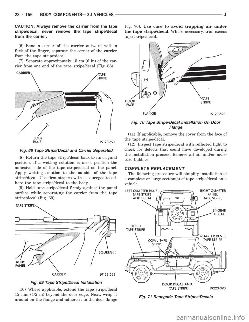
(6) Bend a corner of the carrier outward with a
flick of the finger, separate the corner of the carrier
from the tape stripe/decal.
(7) Separate approximately 15 cm (6 in) of the car-
rier from one end of the tape stripe/decal (Fig. 68).
(8) Return the tape stripe/decal back to its original
position. If a wetting solution is used, position the
adhesive side of the tape stripe/decal on the panel.
Apply wetting solution to the outside of the tape
stripe/decal. Use firm strokes with a squeegee to ad-
here the tape stripe/decal to the body.
(9) Hold tape stripe/decal firmly against the panel
surface while separating the carrier from the tape
stripe/decal (Fig. 69).
(10) Where applicable, extend the tape stripe/decal
12 mm (1/2 in) beyond the door edge. Next, wrap it
around on the flange and adhere it to the door flangeFig. 70).Use care to avoid trapping air under
the tape stripe/decal.Where necessary, trim excess
tape stripe/decal.
(11) If applicable, remove the cover from the face of
the tape stripe/decal.
(12) Inspect tape stripe/decal with reflected light to
check for defects that could have developed during
the installation process. Remove all air and/or mois-
ture bubbles.
COMPLETE REPLACEMENT
The following procedure will simplify installation of
a complete or large section(s) of tape stripe/decal on a
vehicle.
Fig. 68 Tape Stripe/Decal and Carrier Separated
Fig. 69 Tape Stripe/Decal Installation
Fig. 70 Tape Stripe/Decal Installation On Door
Flange
Fig. 71 Renegade Tape Stripes/Decals
23 - 156 BODY COMPONENTSÐXJ VEHICLESJ
Page 1612 of 1784
(1) Place the tape stripe/decal on a clean, flat sur-
face with the carrier side facing upward.
(2) Bend a corner of the carrier inward and then,
with a flick of the finger, separate the corner of the
carrier from the tape stripe/decal.
CAUTION: Hold tape stripe/decal at extreme outer
edges of the corners while separating the carrier.(3) Hold tape stripe/decal firmly against the flat
surface and separate the carrier from the tape stripe/
decal.
If hot and humid, a slight jerking motion will
aid separating the carrier from the tape stripe/
decal.
(4) Use a clean sponge and apply ample wetting
solution to the tape stripe/decal adhesive and to the
painted panel surface. The solution will permit ease
of tape stripe/decal movement when positioning it on
the panel.
(5) Position adhesive-coated side of tape stripe/de-
cal on the panel with the bottom aligned with char-
acter line. Where applicable:
²align the end of the replacement tape stripe/decal
with the end of the existing tape stripe/decal, and
²correctly align the index darts and index notches.
(6) If a complete replacement tape stripe/decal is
not being installed:
²position the replacement tape stripe/decal section
at the center of the repair area,
²align it with the existing tape stripe/decal, and
²allow at least 12 mm (1/2 in) of the tape stripe/de-
cal section to overlap the existing tape stripe/decal
edges.
(7) Apply wetting solution to the outer side of the
tape stripe/decal to allow the squeegee to freely slide
while adhering the stripe/decal to the panel.
CAUTION: Avoid unnecessary pulling and stretch-
ing at the ends of the tape stripe/decal because this
could cause it to tear.
(8) Position and slide a squeegee from the center to
the ends of the tape stripe/decal. This will ensure
complete bonding of the tape stripe/decal to the
painted panel surface.
(9) If a wrinkle is trapped in the tape stripe/decal
during the squeegee operation, stop. Lift wrinkled
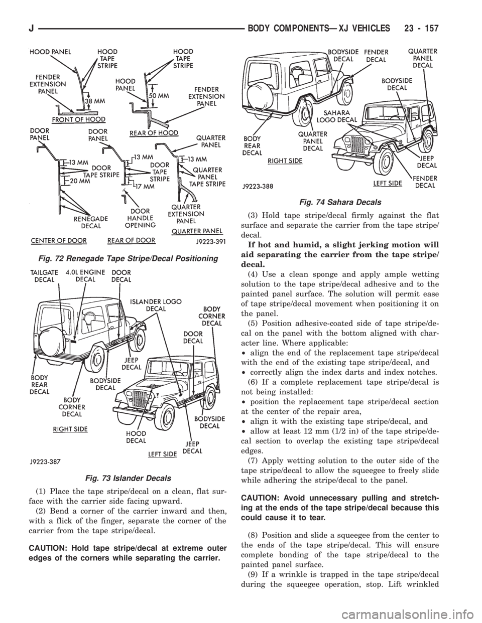
Fig. 72 Renegade Tape Stripe/Decal Positioning
Fig. 73 Islander Decals
Fig. 74 Sahara Decals
JBODY COMPONENTSÐXJ VEHICLES 23 - 157
Page 1613 of 1784
area and re-align stripe/decal with panel character
line.Do not lift the tape stripe/decal if only a
few air bubbles exist.
(10) Where applicable, allow 12 mm (1/2 in) extra
tape stripe/decal to extend beyond the edges to be
folded over.
(11) Fold the excess tape stripe/decal back onto in-
side flange area.Use care to avoid trapping air
under the tape stripe/decal.Where necessary,
trim excess tape stripe/decal.
(12) Inspect tape installation with reflected light to
detect any defects that could have developed during
the installation.
(13) Remove all air and moisture bubbles from the
tape stripe/decal with a needle or pin.
(14) Install any removed components and clean the
vehicle as necessary.
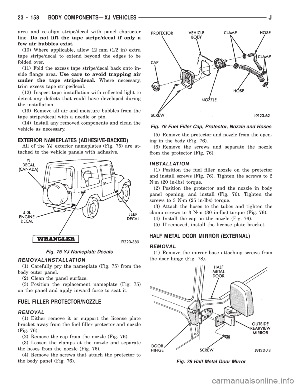
EXTERIOR NAMEPLATES (ADHESIVE-BACKED)
All of the YJ exterior nameplates (Fig. 75) are at-
tached to the vehicle panels with adhesive.
REMOVAL/INSTALLATION
(1) Carefully pry the nameplate (Fig. 75) from the
body outer panel.
(2) Clean the panel surface.
(3) Position the replacement nameplate (Fig. 75)
on the panel and apply inward force to seat it.
FUEL FILLER PROTECTOR/NOZZLE
REMOVAL
(1) Either remove it or support the license plate
bracket away from the fuel filler protector and nozzle
(Fig. 76).
(2) Remove the cap from the nozzle (Fig. 76).
(3) Loosen the clamps at the nozzle and separate
the hoses from the nozzle (Fig. 76).
(4) Remove the screws that attach the protector to
the body panel (Fig. 76).(5) Remove the protector and nozzle from the open-
ing in the body (Fig. 76).
(6) Remove the screws and separate the nozzle
from the protector (Fig. 76).
INSTALLATION
(1) Position the fuel filler nozzle on the protector
and install screws (Fig. 76). Tighten the screws to 2
Nzm (20 in-lbs) torque.
(2) Position the protector and the nozzle in body
panel opening, and install (Fig. 76). Tighten the
screws to 3 Nzm (25 in-lbs) torque.
(3) Attach the hoses to the tubes and tighten the
clamp screws to 3 Nzm (30 in-lbs) torque (Fig. 76).
(4) Install the cap on the nozzle (Fig. 76).
(5) If removed, install the license plate bracket.
HALF METAL DOOR MIRROR (EXTERNAL)
REMOVAL
(1) Remove the mirror base attaching screws from
the door hinge (Fig. 78).
Fig. 76 Fuel Filler Cap, Protector, Nozzle and Hoses
Fig. 78 Half Metal Door Mirror
Fig. 75 YJ Nameplate Decals
23 - 158 BODY COMPONENTSÐXJ VEHICLESJ
Page 1614 of 1784
(2) Remove the mirror from the door hinge (Fig.
78).
INSTALLATION
(1) Clean the door hinge-mirror base contact sur-
face.
(2) Position the mirror base at the door hinge (Fig.
78).
(3) Install the mirror base attaching screws in the
door hinge (Fig. 78). Tighten the attaching screws to
11 Nzm (96 in-lbs) torque.
TAILGATE SERVICE INFORMATION
The following tailgate service procedures include:
²tailgate removal/installation,
²tailgate hinge replacement,
²tailgate adjustment,
²tailgate latch removal/installation,
²tailgate lock cylinder removal/installation,
²tailgate latch striker removal/installation, and
²tailgate seal replacement.
TAILGATE SERVICE
REMOVAL
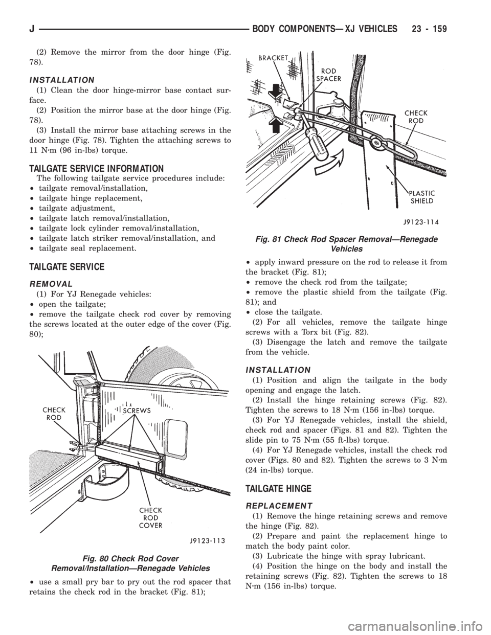
(1) For YJ Renegade vehicles:
²open the tailgate;
²remove the tailgate check rod cover by removing
the screws located at the outer edge of the cover (Fig.
80);
²use a small pry bar to pry out the rod spacer that
retains the check rod in the bracket (Fig. 81);²apply inward pressure on the rod to release it from
the bracket (Fig. 81);
²remove the check rod from the tailgate;
²remove the plastic shield from the tailgate (Fig.
81); and
²close the tailgate.
(2) For all vehicles, remove the tailgate hinge
screws with a Torx bit (Fig. 82).
(3) Disengage the latch and remove the tailgate
from the vehicle.
INSTALLATION
(1) Position and align the tailgate in the body
opening and engage the latch.
(2) Install the hinge retaining screws (Fig. 82).
Tighten the screws to 18 Nzm (156 in-lbs) torque.
(3) For YJ Renegade vehicles, install the shield,
check rod and spacer (Figs. 81 and 82). Tighten the
slide pin to 75 Nzm (55 ft-lbs) torque.
(4) For YJ Renegade vehicles, install the check rod
cover (Figs. 80 and 82). Tighten the screws to 3 Nzm
(24 in-lbs) torque.
TAILGATE HINGE
REPLACEMENT
(1) Remove the hinge retaining screws and remove
the hinge (Fig. 82).
(2) Prepare and paint the replacement hinge to
match the body paint color.
(3) Lubricate the hinge with spray lubricant.
(4) Position the hinge on the body and install the
retaining screws (Fig. 82). Tighten the screws to 18
Nzm (156 in-lbs) torque.
Fig. 80 Check Rod Cover
Removal/InstallationÐRenegade Vehicles
Fig. 81 Check Rod Spacer RemovalÐRenegade
Vehicles
JBODY COMPONENTSÐXJ VEHICLES 23 - 159
Page 1615 of 1784
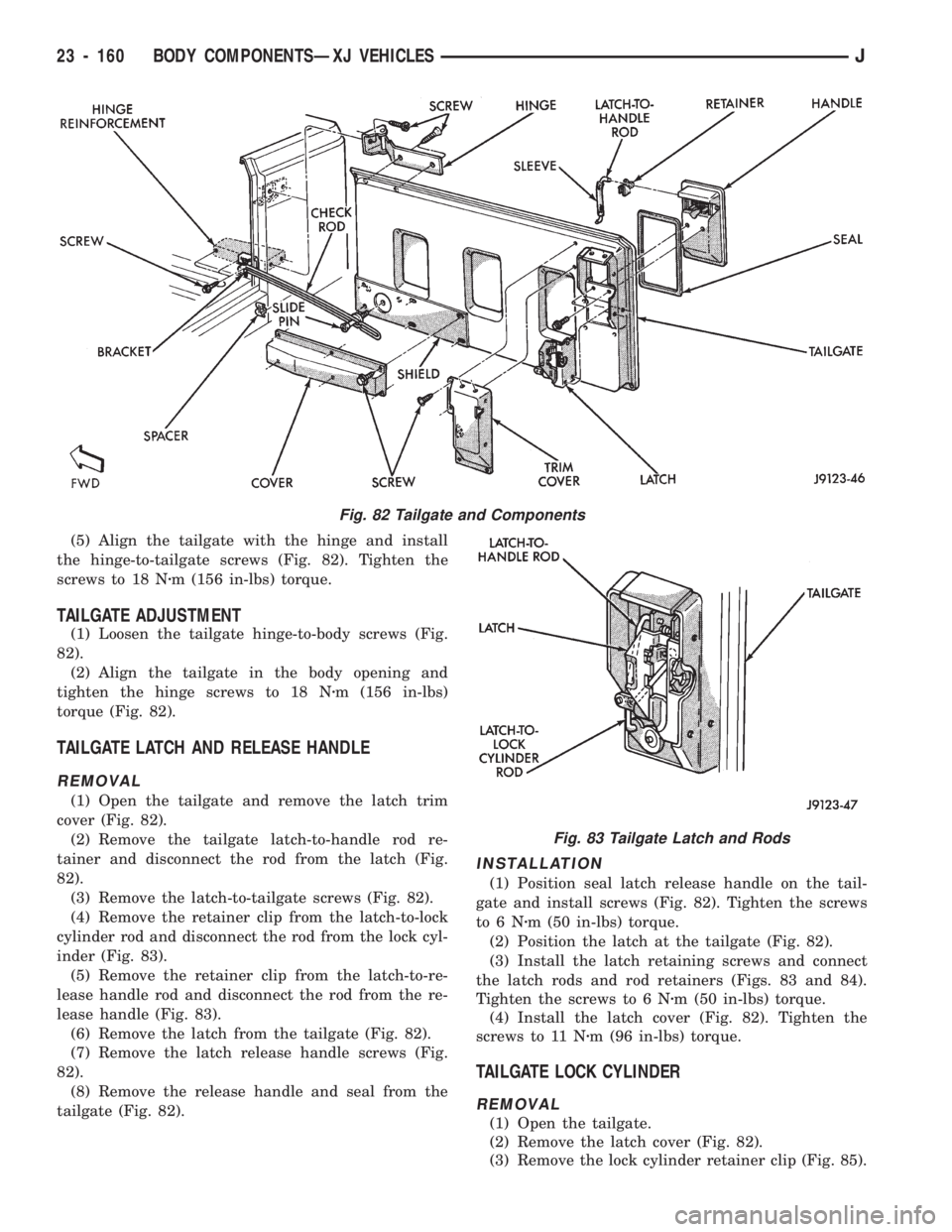
(5) Align the tailgate with the hinge and install
the hinge-to-tailgate screws (Fig. 82). Tighten the
screws to 18 Nzm (156 in-lbs) torque.
TAILGATE ADJUSTMENT
(1) Loosen the tailgate hinge-to-body screws (Fig.
82).
(2) Align the tailgate in the body opening and
tighten the hinge screws to 18 Nzm (156 in-lbs)
torque (Fig. 82).
TAILGATE LATCH AND RELEASE HANDLE
REMOVAL
(1) Open the tailgate and remove the latch trim
cover (Fig. 82).
(2) Remove the tailgate latch-to-handle rod re-
tainer and disconnect the rod from the latch (Fig.
82).
(3) Remove the latch-to-tailgate screws (Fig. 82).
(4) Remove the retainer clip from the latch-to-lock
cylinder rod and disconnect the rod from the lock cyl-
inder (Fig. 83).
(5) Remove the retainer clip from the latch-to-re-
lease handle rod and disconnect the rod from the re-
lease handle (Fig. 83).
(6) Remove the latch from the tailgate (Fig. 82).
(7) Remove the latch release handle screws (Fig.
82).
(8) Remove the release handle and seal from the
tailgate (Fig. 82).
INSTALLATION
(1) Position seal latch release handle on the tail-
gate and install screws (Fig. 82). Tighten the screws
to6Nzm (50 in-lbs) torque.
(2) Position the latch at the tailgate (Fig. 82).
(3) Install the latch retaining screws and connect
the latch rods and rod retainers (Figs. 83 and 84).
Tighten the screws to 6 Nzm (50 in-lbs) torque.
(4) Install the latch cover (Fig. 82). Tighten the
screws to 11 Nzm (96 in-lbs) torque.
TAILGATE LOCK CYLINDER
REMOVAL
(1) Open the tailgate.
(2) Remove the latch cover (Fig. 82).
(3) Remove the lock cylinder retainer clip (Fig. 85).
Fig. 82 Tailgate and Components
Fig. 83 Tailgate Latch and Rods
23 - 160 BODY COMPONENTSÐXJ VEHICLESJ
Page 1616 of 1784
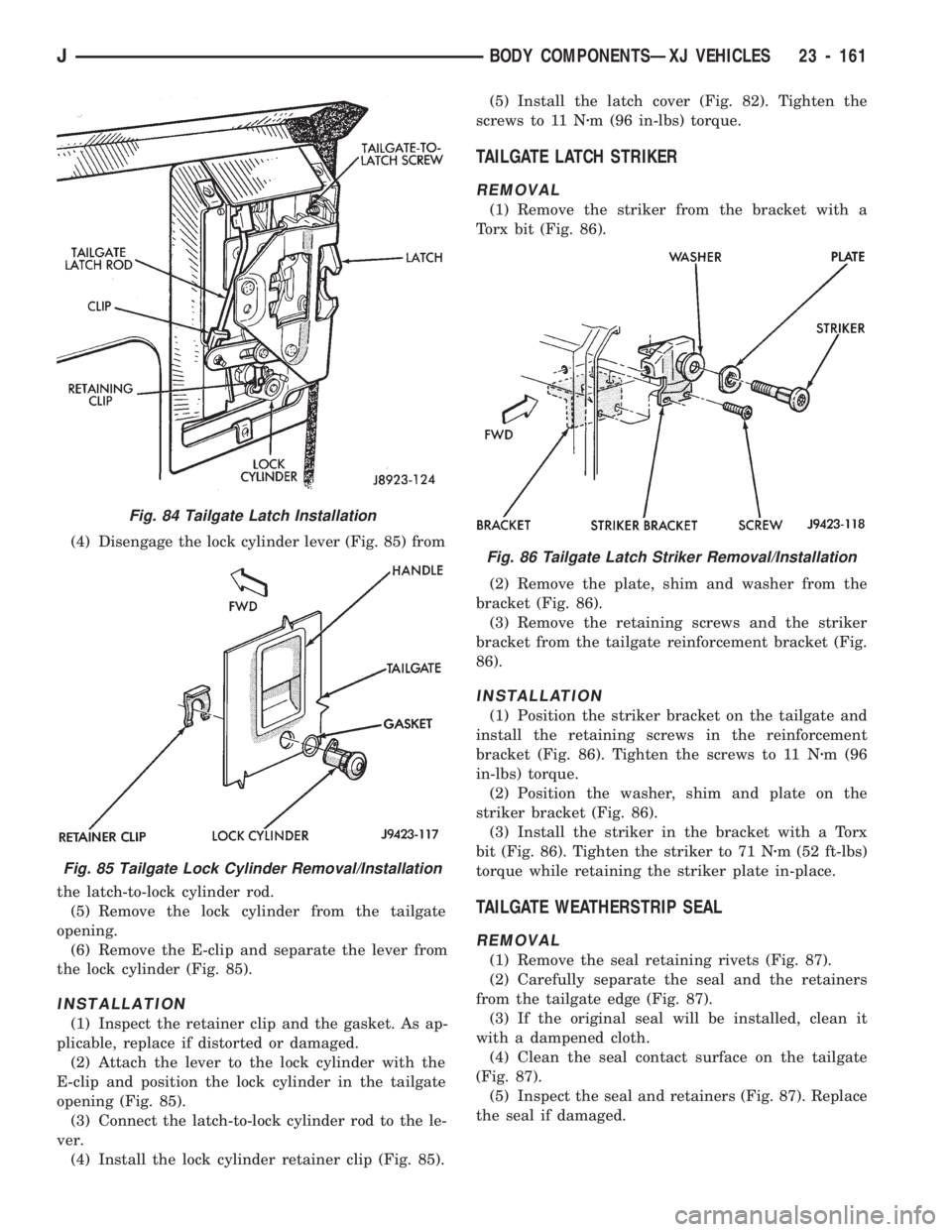
(4) Disengage the lock cylinder lever (Fig. 85) from
the latch-to-lock cylinder rod.
(5) Remove the lock cylinder from the tailgate
opening.
(6) Remove the E-clip and separate the lever from
the lock cylinder (Fig. 85).
INSTALLATION
(1) Inspect the retainer clip and the gasket. As ap-
plicable, replace if distorted or damaged.
(2) Attach the lever to the lock cylinder with the
E-clip and position the lock cylinder in the tailgate
opening (Fig. 85).
(3) Connect the latch-to-lock cylinder rod to the le-
ver.
(4) Install the lock cylinder retainer clip (Fig. 85).(5) Install the latch cover (Fig. 82). Tighten the
screws to 11 Nzm (96 in-lbs) torque.
TAILGATE LATCH STRIKER
REMOVAL
(1) Remove the striker from the bracket with a
Torx bit (Fig. 86).
(2) Remove the plate, shim and washer from the
bracket (Fig. 86).
(3) Remove the retaining screws and the striker
bracket from the tailgate reinforcement bracket (Fig.
86).
INSTALLATION
(1) Position the striker bracket on the tailgate and
install the retaining screws in the reinforcement
bracket (Fig. 86). Tighten the screws to 11 Nzm (96
in-lbs) torque.
(2) Position the washer, shim and plate on the
striker bracket (Fig. 86).
(3) Install the striker in the bracket with a Torx
bit (Fig. 86). Tighten the striker to 71 Nzm (52 ft-lbs)
torque while retaining the striker plate in-place.
TAILGATE WEATHERSTRIP SEAL
REMOVAL
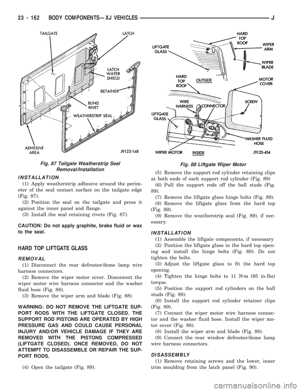
(1) Remove the seal retaining rivets (Fig. 87).
(2) Carefully separate the seal and the retainers
from the tailgate edge (Fig. 87).
(3) If the original seal will be installed, clean it
with a dampened cloth.
(4) Clean the seal contact surface on the tailgate
(Fig. 87).
(5) Inspect the seal and retainers (Fig. 87). Replace
the seal if damaged.
Fig. 84 Tailgate Latch Installation
Fig. 85 Tailgate Lock Cylinder Removal/Installation
Fig. 86 Tailgate Latch Striker Removal/Installation
JBODY COMPONENTSÐXJ VEHICLES 23 - 161
Page 1617 of 1784
INSTALLATION
(1) Apply weatherstrip adhesive around the perim-
eter of the seal contact surface on the tailgate edge
(Fig. 87).
(2) Position the seal on the tailgate and press it
against the inner panel and flange.
(3) Install the seal retaining rivets (Fig. 87).
CAUTION: Do not apply graphite, brake fluid or wax
to the seal.
HARD TOP LIFTGATE GLASS
REMOVAL
(1) Disconnect the rear defroster/dome lamp wire
harness connectors.
(2) Remove the wiper motor cover. Disconnect the
wiper motor wire harness connector and the washer
fluid hose (Fig. 88).
(3) Remove the wiper arm and blade (Fig. 88).
WARNING: DO NOT REMOVE THE LIFTGATE SUP-
PORT RODS WITH THE LIFTGATE CLOSED. THE
SUPPORT ROD PISTONS ARE OPERATED BY HIGH
PRESSURE GAS AND COULD CAUSE PERSONAL
INJURY AND/OR VEHICLE DAMAGE IF THEY ARE
REMOVED WITH THE PISTONS COMPRESSED
(LIFTGATE CLOSED). ONCE REMOVED, DO NOT
ATTEMPT TO DISASSEMBLE OR REPAIR THE SUP-
PORT RODS.
(4) Open the tailgate (Fig. 89).(5) Remove the support rod cylinder retaining clips
at both ends of each support rod cylinder (Fig. 89)
(6) Pull the support rods off the ball studs (Fig.
89).
(7) Remove the liftgate glass hinge bolts (Fig. 89).
(8) Remove the liftgate glass from the hard top
(Fig. 89).
(9) Remove the weatherstrip seal (Fig. 89), if nec-
essary.
INSTALLATION
(1) Assemble the liftgate components, if necessary
(2) Position the liftgate glass in the hard top open-
ing and install the hinge bolts (Fig. 89). Do not
tighten the bolts.
(3) Adjust the liftgate glass to fit the hard top
opening.
(4) Tighten the hinge bolts to 11 Nzm (95 in-lbs)
torque.
(5) Position the support rod cylinders on the ball
studs (Fig. 89).
(6) Install the support rod cylinder retainer clips
(Fig. 89).
(7) Connect the wiper motor wire harness connec-
tor and the washer fluid hose. Install the wiper mo-
tor cover (Fig. 88).
(8) Install the wiper arm and blade (Fig. 88).
(9) Connect the rear window defroster/dome lamp
wire harness connectors.
DISASSEMBLY
(1) Remove retaining screws and the lower, inner
trim moulding from the latch panel (Fig. 90).
Fig. 87 Tailgate Weatherstrip Seal
Removal/InstallationFig. 88 Liftgate Wiper Motor
23 - 162 BODY COMPONENTSÐXJ VEHICLESJ
Page 1618 of 1784
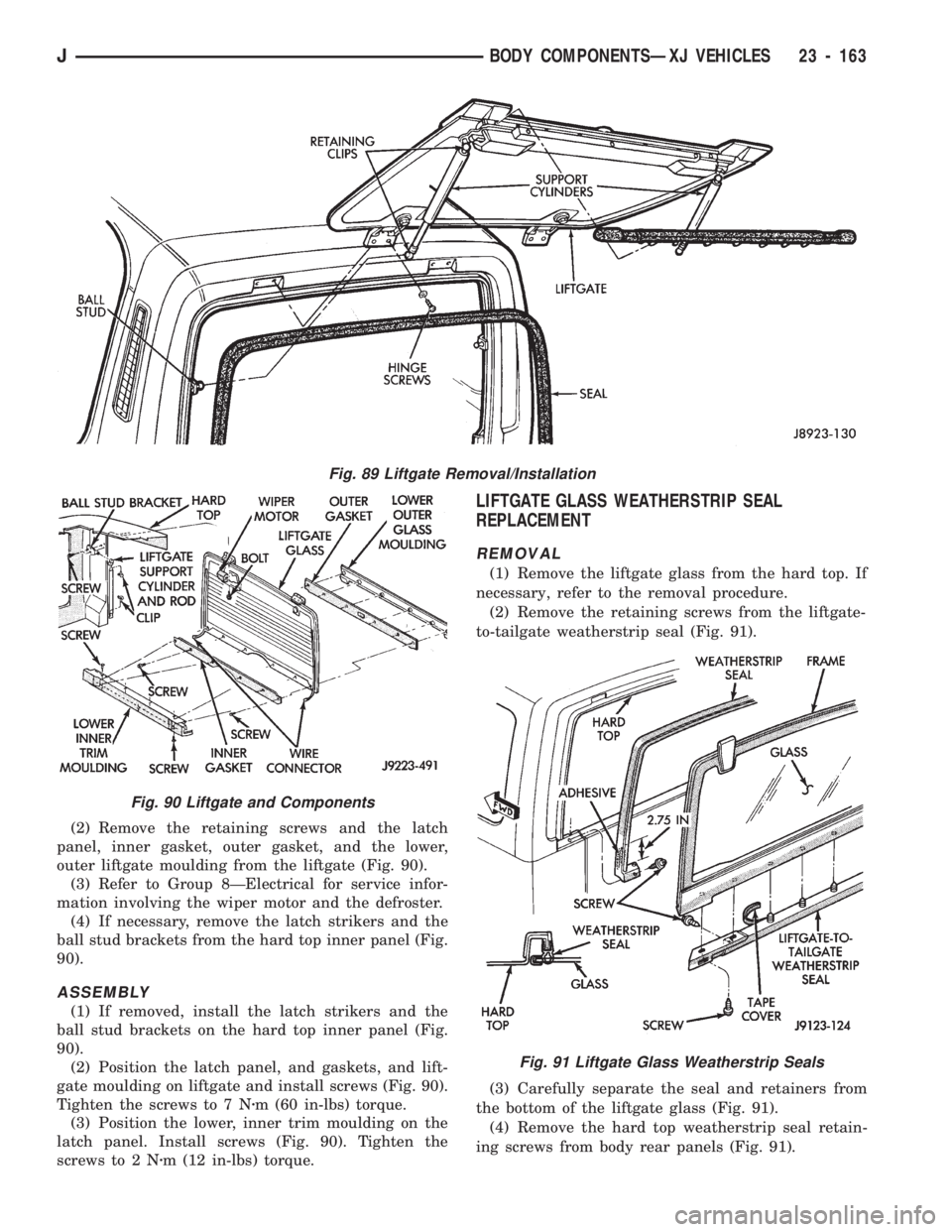
(2) Remove the retaining screws and the latch
panel, inner gasket, outer gasket, and the lower,
outer liftgate moulding from the liftgate (Fig. 90).
(3) Refer to Group 8ÐElectrical for service infor-
mation involving the wiper motor and the defroster.
(4) If necessary, remove the latch strikers and the
ball stud brackets from the hard top inner panel (Fig.
90).
ASSEMBLY
(1) If removed, install the latch strikers and the
ball stud brackets on the hard top inner panel (Fig.
90).
(2) Position the latch panel, and gaskets, and lift-
gate moulding on liftgate and install screws (Fig. 90).
Tighten the screws to 7 Nzm (60 in-lbs) torque.
(3) Position the lower, inner trim moulding on the
latch panel. Install screws (Fig. 90). Tighten the
screws to 2 Nzm (12 in-lbs) torque.
LIFTGATE GLASS WEATHERSTRIP SEAL
REPLACEMENT
REMOVAL
(1) Remove the liftgate glass from the hard top. If
necessary, refer to the removal procedure.
(2) Remove the retaining screws from the liftgate-
to-tailgate weatherstrip seal (Fig. 91).
(3) Carefully separate the seal and retainers from
the bottom of the liftgate glass (Fig. 91).
(4) Remove the hard top weatherstrip seal retain-
ing screws from body rear panels (Fig. 91).
Fig. 91 Liftgate Glass Weatherstrip Seals
Fig. 89 Liftgate Removal/Installation
Fig. 90 Liftgate and Components
JBODY COMPONENTSÐXJ VEHICLES 23 - 163
Page 1619 of 1784
(5) Carefully separate the weatherstrip seal from
the rear panels and the hard top (Fig. 91).
(6) Remove the residual adhesive from the seal
contact areas.
INSTALLATION
(1) Remove the tape cover and position the lift-
gate-to-tailgate weatherstrip seal at the bottom of
the liftgate glass (Fig. 91).
(2) Carefully insert the retainers into the holes
and press the seal against the bottom of the liftgate
glass (Fig. 91).
(3) Install the liftgate-to-tailgate weatherstrip seal
screws (Fig. 91). Tighten the screws securely.
(4) Apply weatherstrip adhesive to the hard top
weatherstrip seal as indicated in Figure 91.
(5) Carefully position the weatherstrip seal on the
rear panels and the hard top (Fig. 91).
(6) Press the seal onto the hard top flange and en-
sure that it is correctly seated on the flange (Fig. 91).
(7) Install the seal retaining screws in the rear
panels and tighten them securely (Fig. 91).
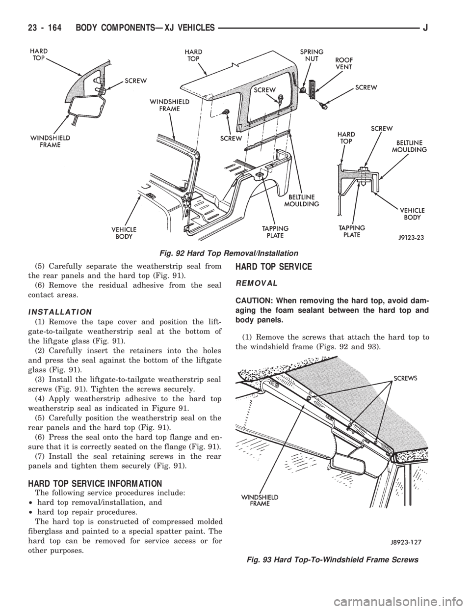
HARD TOP SERVICE INFORMATION
The following service procedures include:
²hard top removal/installation, and
²hard top repair procedures.
The hard top is constructed of compressed molded
fiberglass and painted to a special spatter paint. The
hard top can be removed for service access or for
other purposes.
HARD TOP SERVICE
REMOVAL
CAUTION: When removing the hard top, avoid dam-
aging the foam sealant between the hard top and
body panels.
(1) Remove the screws that attach the hard top to
the windshield frame (Figs. 92 and 93).
Fig. 92 Hard Top Removal/Installation
Fig. 93 Hard Top-To-Windshield Frame Screws
23 - 164 BODY COMPONENTSÐXJ VEHICLESJ
Page 1620 of 1784
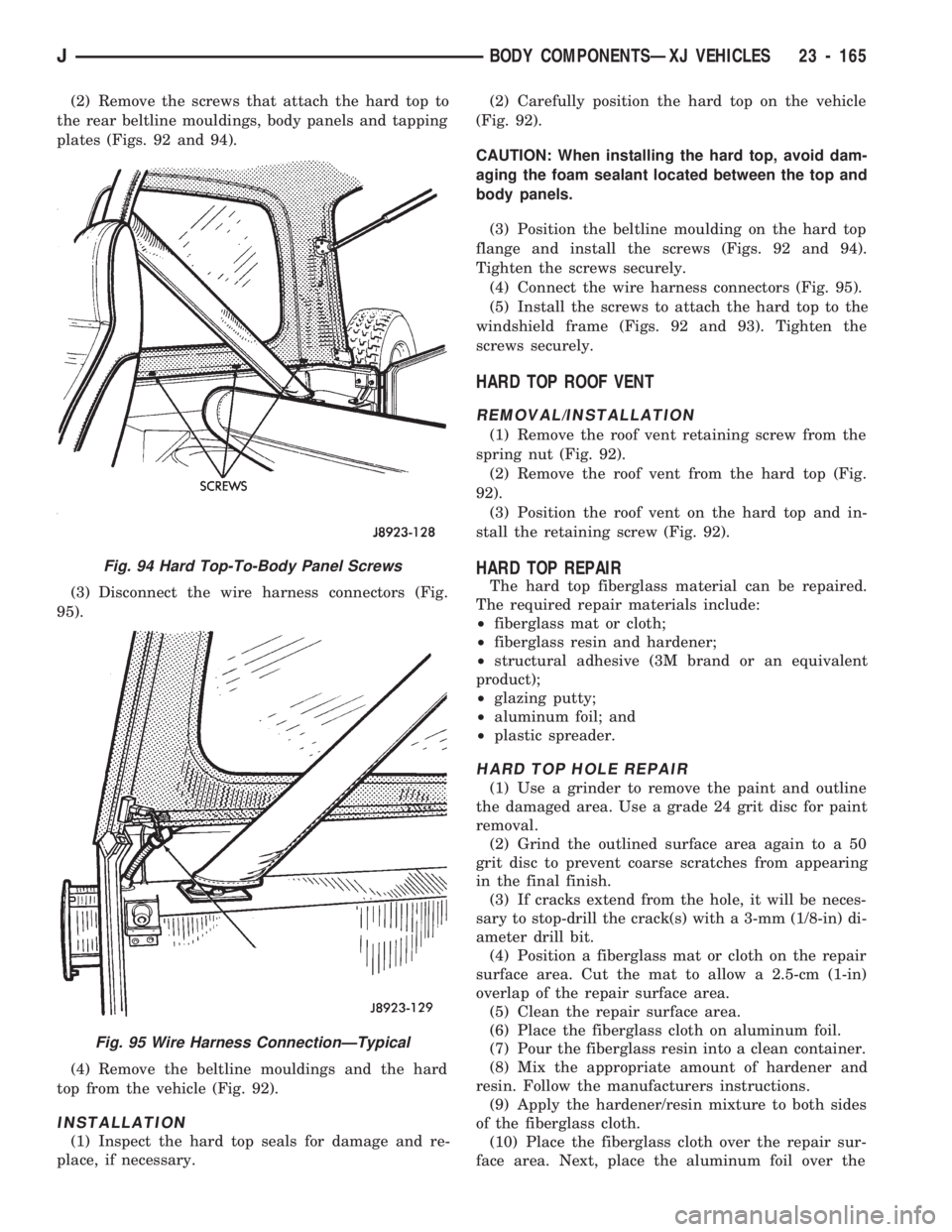
(2) Remove the screws that attach the hard top to
the rear beltline mouldings, body panels and tapping
plates (Figs. 92 and 94).
(3) Disconnect the wire harness connectors (Fig.
95).
(4) Remove the beltline mouldings and the hard
top from the vehicle (Fig. 92).
INSTALLATION
(1) Inspect the hard top seals for damage and re-
place, if necessary.(2) Carefully position the hard top on the vehicle
(Fig. 92).
CAUTION: When installing the hard top, avoid dam-
aging the foam sealant located between the top and
body panels.
(3) Position the beltline moulding on the hard top
flange and install the screws (Figs. 92 and 94).
Tighten the screws securely.
(4) Connect the wire harness connectors (Fig. 95).
(5) Install the screws to attach the hard top to the
windshield frame (Figs. 92 and 93). Tighten the
screws securely.
HARD TOP ROOF VENT
REMOVAL/INSTALLATION
(1) Remove the roof vent retaining screw from the
spring nut (Fig. 92).
(2) Remove the roof vent from the hard top (Fig.
92).
(3) Position the roof vent on the hard top and in-
stall the retaining screw (Fig. 92).
HARD TOP REPAIR
The hard top fiberglass material can be repaired.
The required repair materials include:
²fiberglass mat or cloth;
²fiberglass resin and hardener;
²structural adhesive (3M brand or an equivalent
product);
²glazing putty;
²aluminum foil; and
²plastic spreader.
HARD TOP HOLE REPAIR
(1) Use a grinder to remove the paint and outline
the damaged area. Use a grade 24 grit disc for paint
removal.
(2) Grind the outlined surface area again to a 50
grit disc to prevent coarse scratches from appearing
in the final finish.
(3) If cracks extend from the hole, it will be neces-
sary to stop-drill the crack(s) with a 3-mm (1/8-in) di-
ameter drill bit.
(4) Position a fiberglass mat or cloth on the repair
surface area. Cut the mat to allow a 2.5-cm (1-in)
overlap of the repair surface area.
(5) Clean the repair surface area.
(6) Place the fiberglass cloth on aluminum foil.
(7) Pour the fiberglass resin into a clean container.
(8) Mix the appropriate amount of hardener and
resin. Follow the manufacturers instructions.
(9) Apply the hardener/resin mixture to both sides
of the fiberglass cloth.
(10) Place the fiberglass cloth over the repair sur-
face area. Next, place the aluminum foil over the
Fig. 94 Hard Top-To-Body Panel Screws
Fig. 95 Wire Harness ConnectionÐTypical
JBODY COMPONENTSÐXJ VEHICLES 23 - 165