JEEP CHEROKEE 1994 Service Repair Manual
Manufacturer: JEEP, Model Year: 1994, Model line: CHEROKEE, Model: JEEP CHEROKEE 1994Pages: 1784, PDF Size: 77.09 MB
Page 1591 of 1784
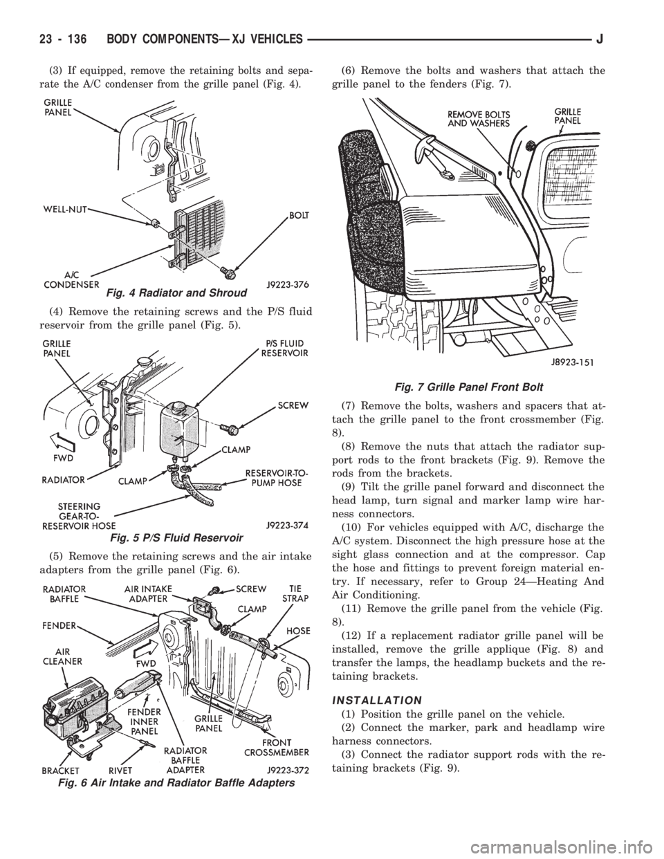
(3) If equipped, remove the retaining bolts and sepa-
rate the A/C condenser from the grille panel (Fig. 4).
(4) Remove the retaining screws and the P/S fluid
reservoir from the grille panel (Fig. 5).
(5) Remove the retaining screws and the air intake
adapters from the grille panel (Fig. 6).(6) Remove the bolts and washers that attach the
grille panel to the fenders (Fig. 7).
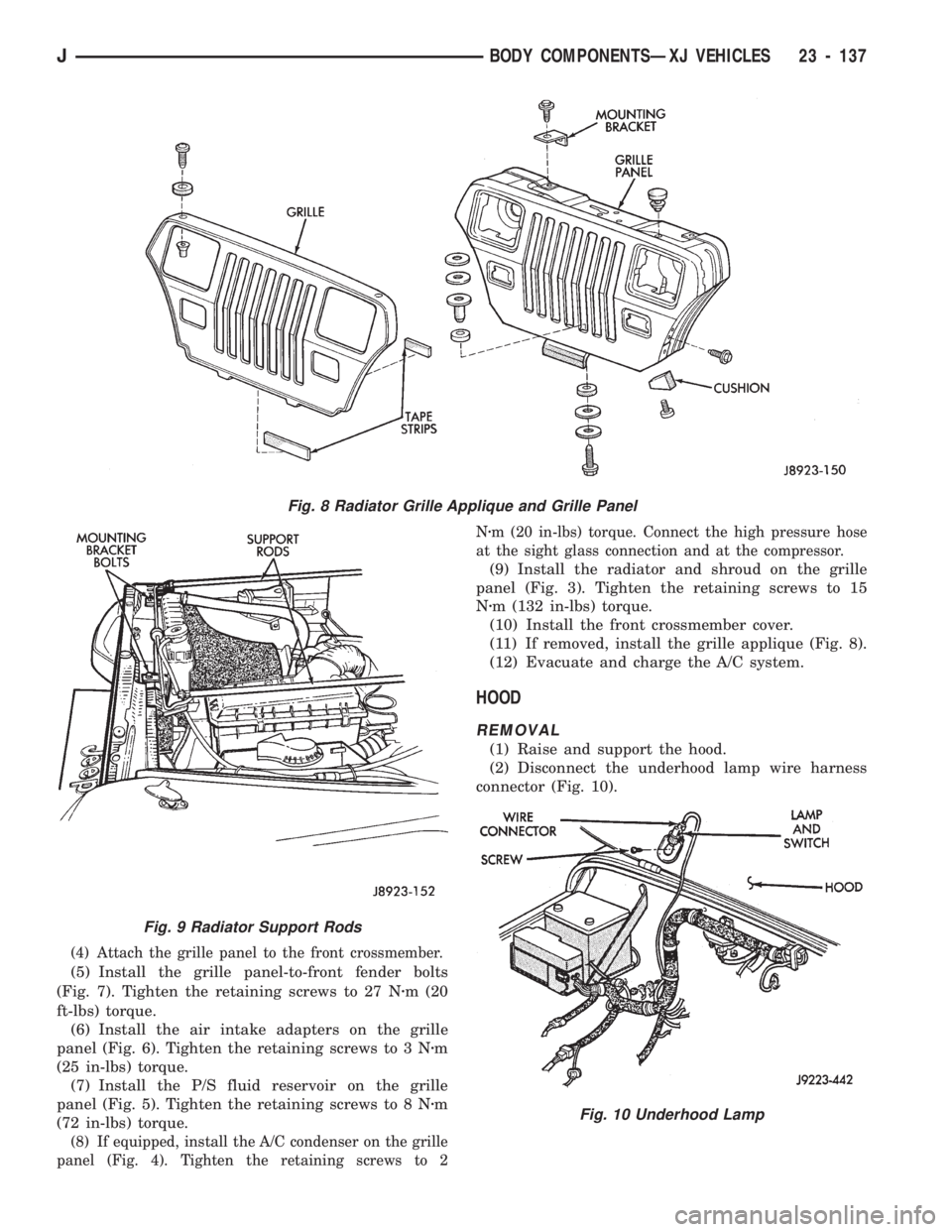
(7) Remove the bolts, washers and spacers that at-
tach the grille panel to the front crossmember (Fig.
8).
(8) Remove the nuts that attach the radiator sup-
port rods to the front brackets (Fig. 9). Remove the
rods from the brackets.
(9) Tilt the grille panel forward and disconnect the
head lamp, turn signal and marker lamp wire har-
ness connectors.
(10) For vehicles equipped with A/C, discharge the
A/C system. Disconnect the high pressure hose at the
sight glass connection and at the compressor. Cap
the hose and fittings to prevent foreign material en-
try. If necessary, refer to Group 24ÐHeating And
Air Conditioning.
(11) Remove the grille panel from the vehicle (Fig.
8).
(12) If a replacement radiator grille panel will be
installed, remove the grille applique (Fig. 8) and
transfer the lamps, the headlamp buckets and the re-
taining brackets.
INSTALLATION
(1) Position the grille panel on the vehicle.
(2) Connect the marker, park and headlamp wire
harness connectors.
(3) Connect the radiator support rods with the re-
taining brackets (Fig. 9).
Fig. 4 Radiator and Shroud
Fig. 5 P/S Fluid Reservoir
Fig. 6 Air Intake and Radiator Baffle Adapters
Fig. 7 Grille Panel Front Bolt
23 - 136 BODY COMPONENTSÐXJ VEHICLESJ
Page 1592 of 1784
(4) Attach the grille panel to the front crossmember.
(5) Install the grille panel-to-front fender bolts
(Fig. 7). Tighten the retaining screws to 27 Nzm (20
ft-lbs) torque.
(6) Install the air intake adapters on the grille
panel (Fig. 6). Tighten the retaining screws to 3 Nzm
(25 in-lbs) torque.
(7) Install the P/S fluid reservoir on the grille
panel (Fig. 5). Tighten the retaining screws to 8 Nzm
(72 in-lbs) torque.
(8) If equipped, install the A/C condenser on the grille
panel (Fig. 4). Tighten the retaining screws to 2Nzm (20 in-lbs) torque. Connect the high pressure hose
at the sight glass connection and at the compressor.
(9) Install the radiator and shroud on the grille
panel (Fig. 3). Tighten the retaining screws to 15
Nzm (132 in-lbs) torque.
(10) Install the front crossmember cover.
(11) If removed, install the grille applique (Fig. 8).
(12) Evacuate and charge the A/C system.
HOOD
REMOVAL
(1) Raise and support the hood.
(2) Disconnect the underhood lamp wire harness
connector (Fig. 10).
Fig. 8 Radiator Grille Applique and Grille Panel
Fig. 9 Radiator Support Rods
Fig. 10 Underhood Lamp
JBODY COMPONENTSÐXJ VEHICLES 23 - 137
Page 1593 of 1784
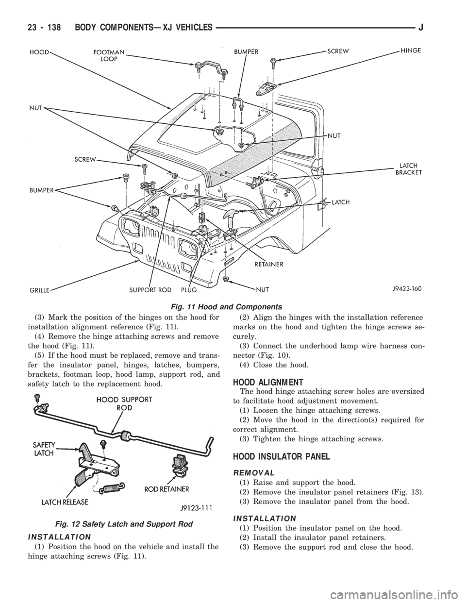
(3) Mark the position of the hinges on the hood for
installation alignment reference (Fig. 11).
(4) Remove the hinge attaching screws and remove
the hood (Fig. 11).
(5) If the hood must be replaced, remove and trans-
fer the insulator panel, hinges, latches, bumpers,
brackets, footman loop, hood lamp, support rod, and
safety latch to the replacement hood.
INSTALLATION
(1) Position the hood on the vehicle and install the
hinge attaching screws (Fig. 11).(2) Align the hinges with the installation reference
marks on the hood and tighten the hinge screws se-
curely.
(3) Connect the underhood lamp wire harness con-
nector (Fig. 10).
(4) Close the hood.
HOOD ALIGNMENT
The hood hinge attaching screw holes are oversized
to facilitate hood adjustment movement.
(1) Loosen the hinge attaching screws.
(2) Move the hood in the direction(s) required for
correct alignment.
(3) Tighten the hinge attaching screws.
HOOD INSULATOR PANEL
REMOVAL
(1) Raise and support the hood.
(2) Remove the insulator panel retainers (Fig. 13).
(3) Remove the insulator panel from the hood.
INSTALLATION
(1) Position the insulator panel on the hood.
(2) Install the insulator panel retainers.
(3) Remove the support rod and close the hood.
Fig. 11 Hood and Components
Fig. 12 Safety Latch and Support Rod
23 - 138 BODY COMPONENTSÐXJ VEHICLESJ
Page 1594 of 1784
HOOD SAFETY LATCH
REMOVAL
(1) Raise and support the hood.
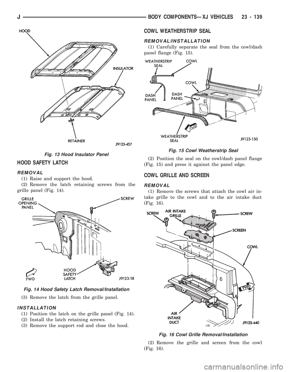
(2) Remove the latch retaining screws from the
grille panel (Fig. 14).
(3) Remove the latch from the grille panel.
INSTALLATION
(1) Position the latch on the grille panel (Fig. 14).
(2) Install the latch retaining screws.
(3) Remove the support rod and close the hood.
COWL WEATHERSTRIP SEAL
REMOVAL/INSTALLATION
(1) Carefully separate the seal from the cowl/dash
panel flange (Fig. 15).
(2) Position the seal on the cowl/dash panel flange
(Fig. 15) and press it against the panel edge.
COWL GRILLE AND SCREEN
REMOVAL
(1) Remove the screws that attach the cowl air in-
take grille to the cowl and to the air intake duct
(Fig. 16).
(2) Remove the grille and screen from the cowl
(Fig. 16).
Fig. 13 Hood Insulator Panel
Fig. 14 Hood Safety Latch Removal/Installation
Fig. 15 Cowl Weatherstrip Seal
Fig. 16 Cowl Grille Removal/Installation
JBODY COMPONENTSÐXJ VEHICLES 23 - 139
Page 1595 of 1784
INSTALLATION
(1) Position the cowl screen and grille on the cowl.
(2) Attach the grille and screen to the cowl and the
air intake duct with the screws (Fig. 16).
BATTERY TRAY
REMOVAL
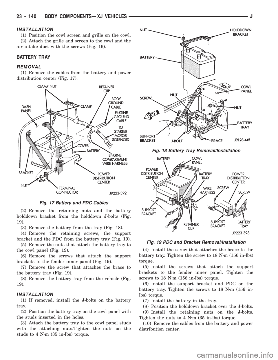
(1) Remove the cables from the battery and power
distribution center (Fig. 17).
(2) Remove the retaining nuts and the battery
holddown bracket from the holddown J-bolts (Fig.
19).
(3) Remove the battery from the tray (Fig. 18).
(4) Remove the retaining screws, the support
bracket and the PDC from the battery tray (Fig. 19).
(5) Remove the nuts that attach the battery tray to
the cowl panel (Fig. 19).
(6) Remove the screws that attach the support
brackets to the fender inner panel (Fig. 19).
(7) Remove the screw that attaches the brace to
the battery tray (Fig. 19).
(8) Remove the battery tray from the vehicle (Fig.
19).
INSTALLATION
(1) If removed, install the J-bolts on the battery
tray.
(2) Position the battery tray on the cowl panel with
the studs inserted in the holes.
(3) Attach the battery tray to the cowl panel studs
with the attaching nuts.Tighten the nuts on the
studs to 4 Nzm (35 in-lbs) torque.(4) Install the screw that attaches the brace to the
battery tray. Tighten the screw to 18 Nzm (156 in-lbs)
torque.
(5) Install the screws that attach the support
brackets to the fender inner panel. Tighten the
screws to 18 Nzm (156 in-lbs) torque.
(6) Install the support bracket and PDC on the
battery tray. Tighten the screws to 18 Nzm (156 in-
lbs) torque.
(7) Install the battery in the tray.
(8) Position the holddown bracket over the J-bolts.
(9) Install the retaining nuts on the J-bolts.
Tighten the nuts to 4 Nzm (35 in-lbs) torque.
(10) Remove the cables from the battery and power
distribution center.
Fig. 17 Battery and PDC Cables
Fig. 18 Battery Tray Removal/Installation
Fig. 19 PDC and Bracket Removal/Installation
23 - 140 BODY COMPONENTSÐXJ VEHICLESJ
Page 1596 of 1784
FENDERS
SERVICE INFORMATION
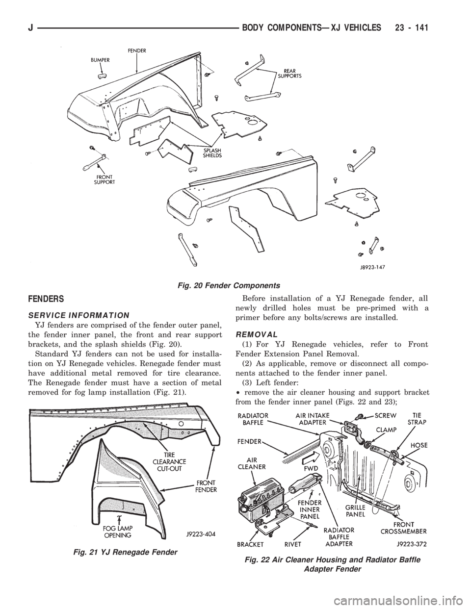
YJ fenders are comprised of the fender outer panel,
the fender inner panel, the front and rear support
brackets, and the splash shields (Fig. 20).
Standard YJ fenders can not be used for installa-
tion on YJ Renegade vehicles. Renegade fender must
have additional metal removed for tire clearance.
The Renegade fender must have a section of metal
removed for fog lamp installation (Fig. 21).Before installation of a YJ Renegade fender, all
newly drilled holes must be pre-primed with a
primer before any bolts/screws are installed.
REMOVAL
(1) For YJ Renegade vehicles, refer to Front
Fender Extension Panel Removal.
(2) As applicable, remove or disconnect all compo-
nents attached to the fender inner panel.
(3) Left fender:
²
remove the air cleaner housing and support bracket
from the fender inner panel (Figs. 22 and 23);
Fig. 20 Fender Components
Fig. 21 YJ Renegade FenderFig. 22 Air Cleaner Housing and Radiator Baffle
Adapter Fender
JBODY COMPONENTSÐXJ VEHICLES 23 - 141
Page 1597 of 1784
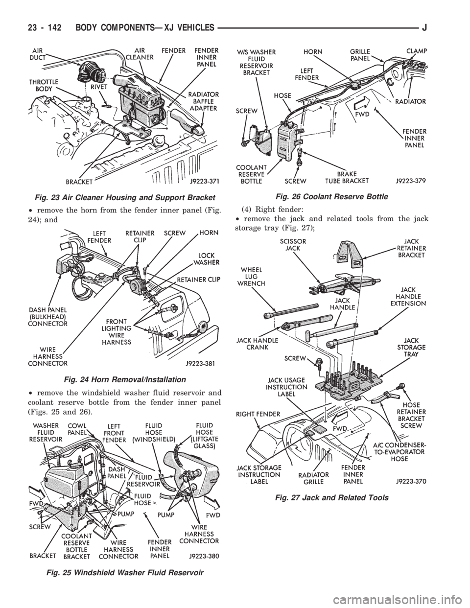
²remove the horn from the fender inner panel (Fig.
24); and
²remove the windshield washer fluid reservoir and
coolant reserve bottle from the fender inner panel
(Figs. 25 and 26).(4) Right fender:
²remove the jack and related tools from the jack
storage tray (Fig. 27);
Fig. 23 Air Cleaner Housing and Support Bracket
Fig. 24 Horn Removal/Installation
Fig. 25 Windshield Washer Fluid Reservoir
Fig. 26 Coolant Reserve Bottle
Fig. 27 Jack and Related Tools
23 - 142 BODY COMPONENTSÐXJ VEHICLESJ
Page 1598 of 1784
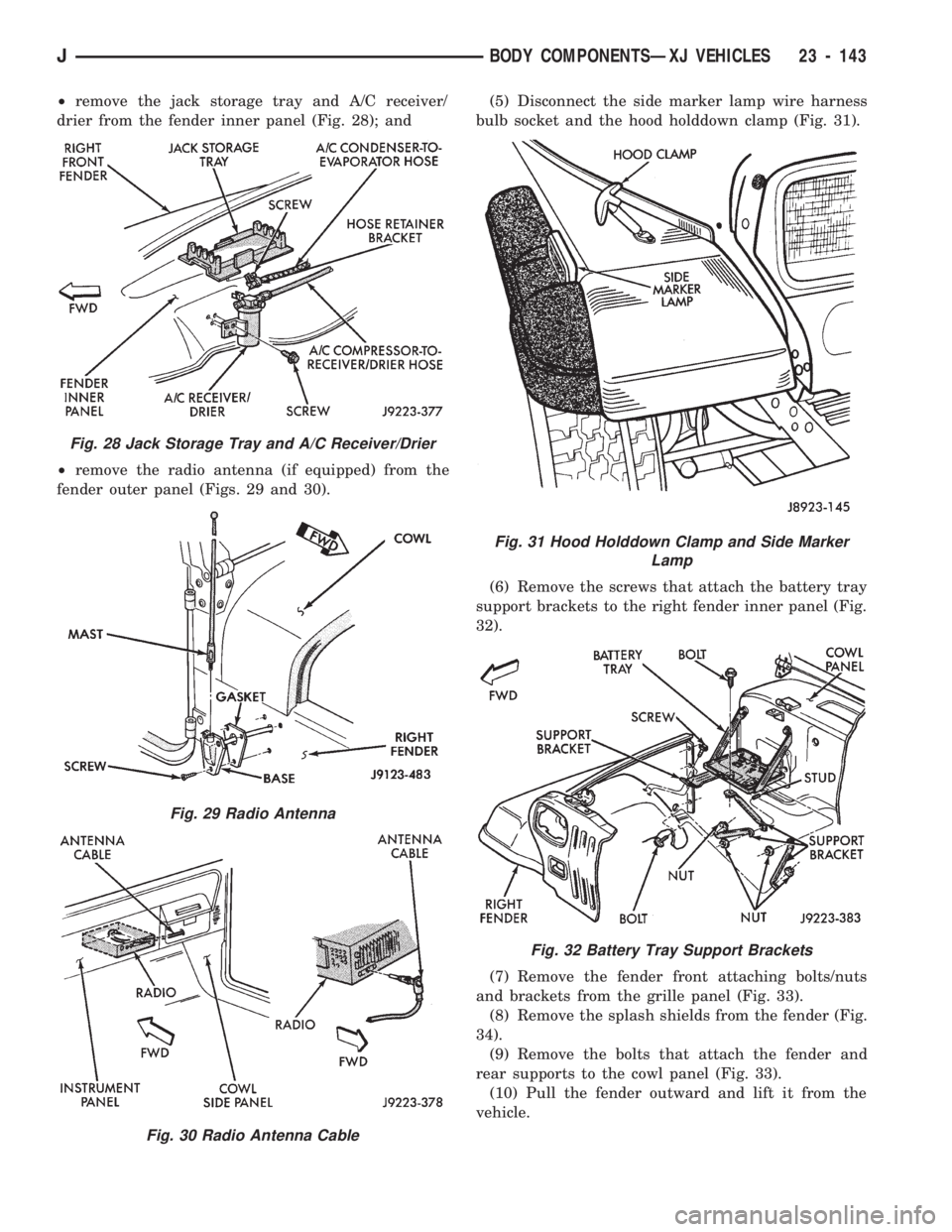
²remove the jack storage tray and A/C receiver/
drier from the fender inner panel (Fig. 28); and
²remove the radio antenna (if equipped) from the
fender outer panel (Figs. 29 and 30).(5) Disconnect the side marker lamp wire harness
bulb socket and the hood holddown clamp (Fig. 31).
(6) Remove the screws that attach the battery tray
support brackets to the right fender inner panel (Fig.
32).
(7) Remove the fender front attaching bolts/nuts
and brackets from the grille panel (Fig. 33).
(8) Remove the splash shields from the fender (Fig.
34).
(9) Remove the bolts that attach the fender and
rear supports to the cowl panel (Fig. 33).
(10) Pull the fender outward and lift it from the
vehicle.
Fig. 28 Jack Storage Tray and A/C Receiver/Drier
Fig. 29 Radio Antenna
Fig. 30 Radio Antenna Cable
Fig. 31 Hood Holddown Clamp and Side Marker
Lamp
Fig. 32 Battery Tray Support Brackets
JBODY COMPONENTSÐXJ VEHICLES 23 - 143
Page 1599 of 1784
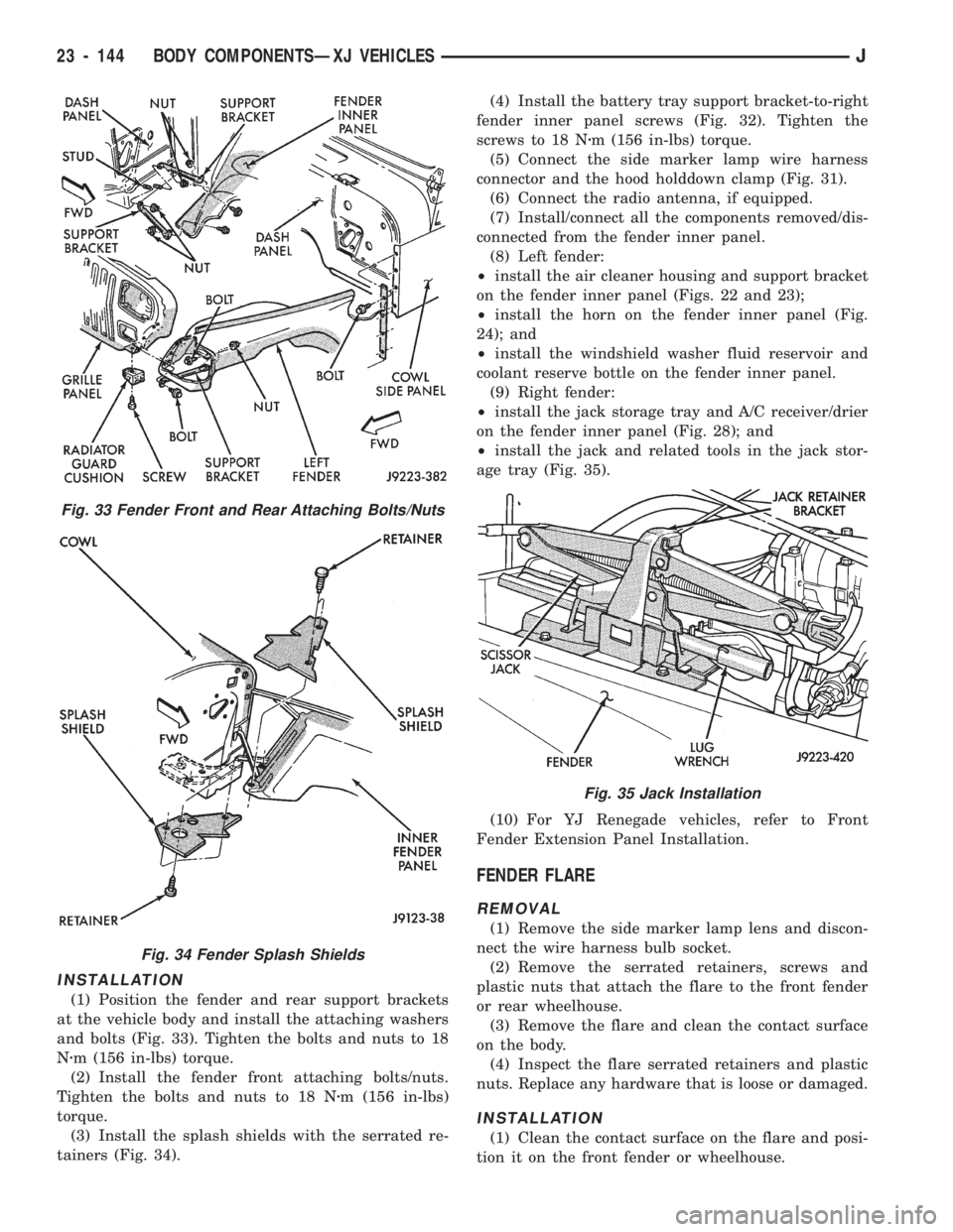
INSTALLATION
(1) Position the fender and rear support brackets
at the vehicle body and install the attaching washers
and bolts (Fig. 33). Tighten the bolts and nuts to 18
Nzm (156 in-lbs) torque.
(2) Install the fender front attaching bolts/nuts.
Tighten the bolts and nuts to 18 Nzm (156 in-lbs)
torque.
(3) Install the splash shields with the serrated re-
tainers (Fig. 34).(4) Install the battery tray support bracket-to-right
fender inner panel screws (Fig. 32). Tighten the
screws to 18 Nzm (156 in-lbs) torque.
(5) Connect the side marker lamp wire harness
connector and the hood holddown clamp (Fig. 31).
(6) Connect the radio antenna, if equipped.
(7) Install/connect all the components removed/dis-
connected from the fender inner panel.
(8) Left fender:
²install the air cleaner housing and support bracket
on the fender inner panel (Figs. 22 and 23);
²install the horn on the fender inner panel (Fig.
24); and
²install the windshield washer fluid reservoir and
coolant reserve bottle on the fender inner panel.
(9) Right fender:
²install the jack storage tray and A/C receiver/drier
on the fender inner panel (Fig. 28); and
²install the jack and related tools in the jack stor-
age tray (Fig. 35).
(10) For YJ Renegade vehicles, refer to Front
Fender Extension Panel Installation.
FENDER FLARE
REMOVAL
(1) Remove the side marker lamp lens and discon-
nect the wire harness bulb socket.
(2) Remove the serrated retainers, screws and
plastic nuts that attach the flare to the front fender
or rear wheelhouse.
(3) Remove the flare and clean the contact surface
on the body.
(4) Inspect the flare serrated retainers and plastic
nuts. Replace any hardware that is loose or damaged.
INSTALLATION
(1) Clean the contact surface on the flare and posi-
tion it on the front fender or wheelhouse.
Fig. 33 Fender Front and Rear Attaching Bolts/Nuts
Fig. 34 Fender Splash Shields
Fig. 35 Jack Installation
23 - 144 BODY COMPONENTSÐXJ VEHICLESJ
Page 1600 of 1784
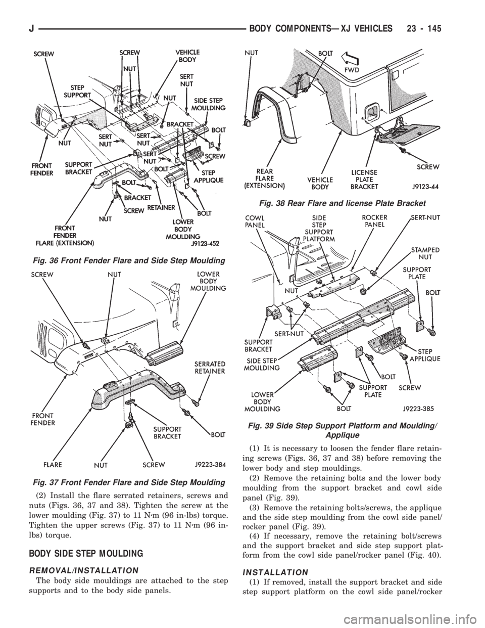
(2) Install the flare serrated retainers, screws and
nuts (Figs. 36, 37 and 38). Tighten the screw at the
lower moulding (Fig. 37) to 11 Nzm (96 in-lbs) torque.
Tighten the upper screws (Fig. 37) to 11 Nzm (96 in-
lbs) torque.
BODY SIDE STEP MOULDING
REMOVAL/INSTALLATION
The body side mouldings are attached to the step
supports and to the body side panels.(1) It is necessary to loosen the fender flare retain-
ing screws (Figs. 36, 37 and 38) before removing the
lower body and step mouldings.
(2) Remove the retaining bolts and the lower body
moulding from the support bracket and cowl side
panel (Fig. 39).
(3) Remove the retaining bolts/screws, the applique
and the side step moulding from the cowl side panel/
rocker panel (Fig. 39).
(4) If necessary, remove the retaining bolt/screws
and the support bracket and side step support plat-
form from the cowl side panel/rocker panel (Fig. 40).
INSTALLATION
(1) If removed, install the support bracket and side
step support platform on the cowl side panel/rocker
Fig. 38 Rear Flare and license Plate Bracket
Fig. 39 Side Step Support Platform and Moulding/
Applique
Fig. 36 Front Fender Flare and Side Step Moulding
Fig. 37 Front Fender Flare and Side Step Moulding
JBODY COMPONENTSÐXJ VEHICLES 23 - 145