JEEP CHEROKEE 1994 Service Repair Manual
Manufacturer: JEEP, Model Year: 1994, Model line: CHEROKEE, Model: JEEP CHEROKEE 1994Pages: 1784, PDF Size: 77.09 MB
Page 1651 of 1784
FRONT SHOULDER BELTS
REMOVAL
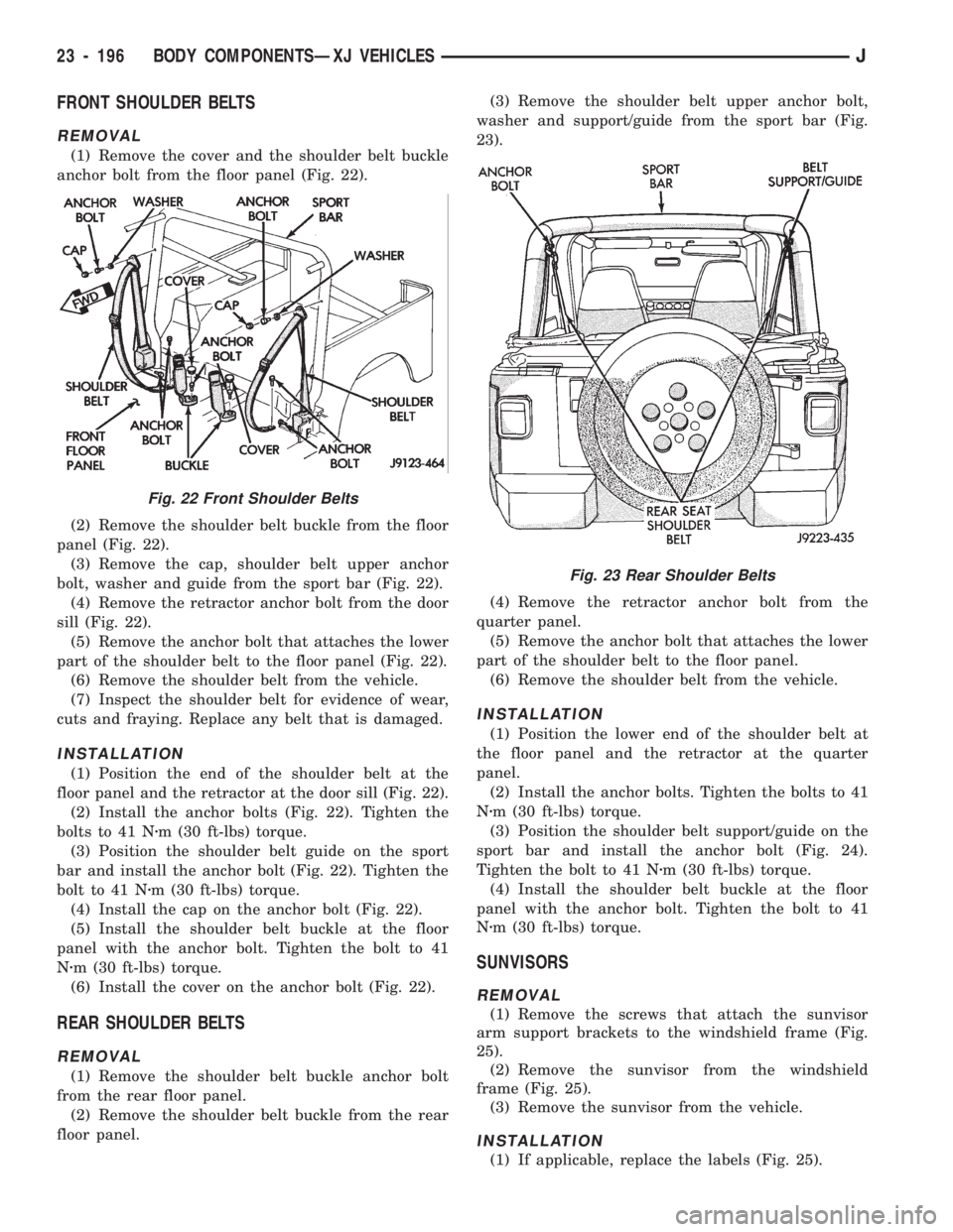
(1) Remove the cover and the shoulder belt buckle
anchor bolt from the floor panel (Fig. 22).
(2) Remove the shoulder belt buckle from the floor
panel (Fig. 22).
(3) Remove the cap, shoulder belt upper anchor
bolt, washer and guide from the sport bar (Fig. 22).
(4) Remove the retractor anchor bolt from the door
sill (Fig. 22).
(5) Remove the anchor bolt that attaches the lower
part of the shoulder belt to the floor panel (Fig. 22).
(6) Remove the shoulder belt from the vehicle.
(7) Inspect the shoulder belt for evidence of wear,
cuts and fraying. Replace any belt that is damaged.
INSTALLATION
(1) Position the end of the shoulder belt at the
floor panel and the retractor at the door sill (Fig. 22).
(2) Install the anchor bolts (Fig. 22). Tighten the
bolts to 41 Nzm (30 ft-lbs) torque.
(3) Position the shoulder belt guide on the sport
bar and install the anchor bolt (Fig. 22). Tighten the
bolt to 41 Nzm (30 ft-lbs) torque.
(4) Install the cap on the anchor bolt (Fig. 22).
(5) Install the shoulder belt buckle at the floor
panel with the anchor bolt. Tighten the bolt to 41
Nzm (30 ft-lbs) torque.
(6) Install the cover on the anchor bolt (Fig. 22).
REAR SHOULDER BELTS
REMOVAL
(1) Remove the shoulder belt buckle anchor bolt
from the rear floor panel.
(2) Remove the shoulder belt buckle from the rear
floor panel.(3) Remove the shoulder belt upper anchor bolt,
washer and support/guide from the sport bar (Fig.
23).
(4) Remove the retractor anchor bolt from the
quarter panel.
(5) Remove the anchor bolt that attaches the lower
part of the shoulder belt to the floor panel.
(6) Remove the shoulder belt from the vehicle.
INSTALLATION
(1) Position the lower end of the shoulder belt at
the floor panel and the retractor at the quarter
panel.
(2) Install the anchor bolts. Tighten the bolts to 41
Nzm (30 ft-lbs) torque.
(3) Position the shoulder belt support/guide on the
sport bar and install the anchor bolt (Fig. 24).
Tighten the bolt to 41 Nzm (30 ft-lbs) torque.
(4) Install the shoulder belt buckle at the floor
panel with the anchor bolt. Tighten the bolt to 41
Nzm (30 ft-lbs) torque.
SUNVISORS
REMOVAL
(1) Remove the screws that attach the sunvisor
arm support brackets to the windshield frame (Fig.
25).
(2) Remove the sunvisor from the windshield
frame (Fig. 25).
(3) Remove the sunvisor from the vehicle.
INSTALLATION
(1) If applicable, replace the labels (Fig. 25).
Fig. 22 Front Shoulder Belts
Fig. 23 Rear Shoulder Belts
23 - 196 BODY COMPONENTSÐXJ VEHICLESJ
Page 1652 of 1784
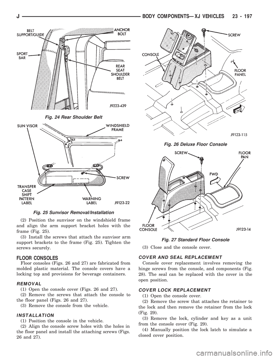
(2) Position the sunvisor on the windshield frame
and align the arm support bracket holes with the
frame (Fig. 25).
(3) Install the screws that attach the sunvisor arm
support brackets to the frame (Fig. 25). Tighten the
screws securely.
FLOOR CONSOLES
Floor consoles (Figs. 26 and 27) are fabricated from
molded plastic material. The console covers have a
locking top and provisions for beverage containers.
REMOVAL
(1) Open the console cover (Figs. 26 and 27).
(2) Remove the screws that attach the console to
the floor panel (Figs. 26 and 27).
(3) Remove the console from the vehicle.
INSTALLATION
(1) Position the console in the vehicle.
(2) Align the console screw holes with the holes in
the floor panel and install the attaching screws (Figs.
26 and 27).(3) Close and the console cover.
COVER AND SEAL REPLACEMENT
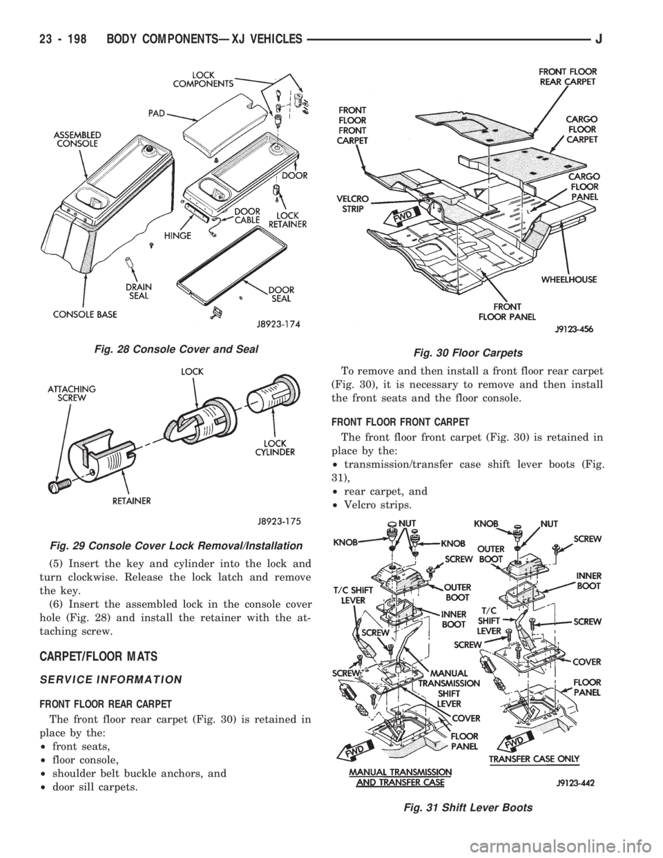
Console cover replacement involves removing the
hinge screws from the console, and components (Fig.
28). The seal can be replaced with the cover in the
open position.
COVER LOCK REPLACEMENT
(1) Open the console cover.
(2) Remove the screw that attaches the retainer to
the lock and then remove the retainer from the lock
(Fig. 29).
(3) Remove the lock, cylinder and key as a unit
from the console cover (Fig. 29).
(4) Manually position the lock latch to simulate a
closed cover position.
Fig. 24 Rear Shoulder Belt
Fig. 25 Sunvisor Removal/Installation
Fig. 26 Deluxe Floor Console
Fig. 27 Standard Floor Console
JBODY COMPONENTSÐXJ VEHICLES 23 - 197
Page 1653 of 1784
(5) Insert the key and cylinder into the lock and
turn clockwise. Release the lock latch and remove
the key.
(6) Insert the assembled lock in the console cover
hole (Fig. 28) and install the retainer with the at-
taching screw.
CARPET/FLOOR MATS
SERVICE INFORMATION
FRONT FLOOR REAR CARPET
The front floor rear carpet (Fig. 30) is retained in
place by the:
²front seats,
²floor console,
²shoulder belt buckle anchors, and
²door sill carpets.To remove and then install a front floor rear carpet
(Fig. 30), it is necessary to remove and then install
the front seats and the floor console.
FRONT FLOOR FRONT CARPET
The front floor front carpet (Fig. 30) is retained in
place by the:
²transmission/transfer case shift lever boots (Fig.
31),
²rear carpet, and
²Velcro strips.
Fig. 28 Console Cover and Seal
Fig. 29 Console Cover Lock Removal/Installation
Fig. 30 Floor Carpets
Fig. 31 Shift Lever Boots
23 - 198 BODY COMPONENTSÐXJ VEHICLESJ
Page 1654 of 1784
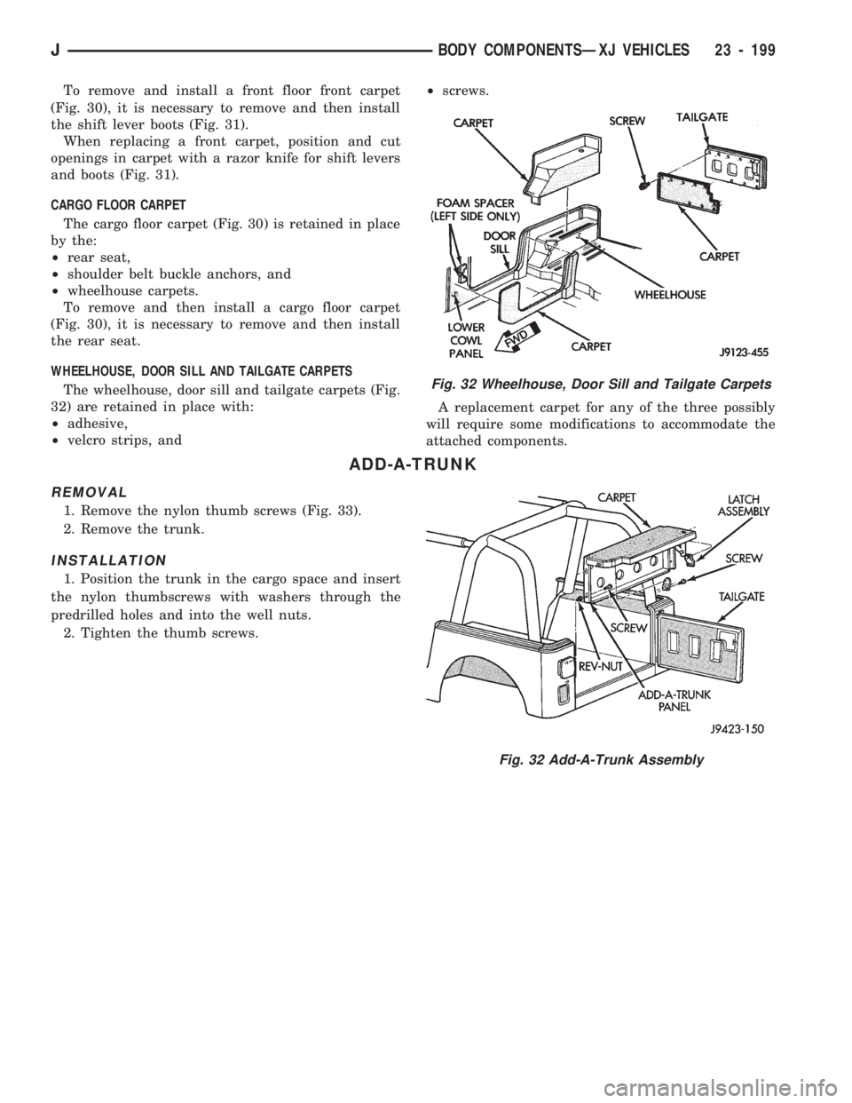
To remove and install a front floor front carpet
(Fig. 30), it is necessary to remove and then install
the shift lever boots (Fig. 31).
When replacing a front carpet, position and cut
openings in carpet with a razor knife for shift levers
and boots (Fig. 31).
CARGO FLOOR CARPET
The cargo floor carpet (Fig. 30) is retained in place
by the:
²rear seat,
²shoulder belt buckle anchors, and
²wheelhouse carpets.
To remove and then install a cargo floor carpet
(Fig. 30), it is necessary to remove and then install
the rear seat.
WHEELHOUSE, DOOR SILL AND TAILGATE CARPETS
The wheelhouse, door sill and tailgate carpets (Fig.
32) are retained in place with:
²adhesive,
²velcro strips, and²screws.
A replacement carpet for any of the three possibly
will require some modifications to accommodate the
attached components.
ADD-A-TRUNK
REMOVAL
1. Remove the nylon thumb screws (Fig. 33).
2. Remove the trunk.
INSTALLATION
1. Position the trunk in the cargo space and insert
the nylon thumbscrews with washers through the
predrilled holes and into the well nuts.
2. Tighten the thumb screws.
Fig. 32 Wheelhouse, Door Sill and Tailgate Carpets
Fig. 32 Add-A-Trunk Assembly
JBODY COMPONENTSÐXJ VEHICLES 23 - 199
Page 1655 of 1784
BODY COMPONENTSÐREFINISHING
CONTENTS
page page
PAINT APPLICATION................... 201SERVICE INFORMATION................ 200
SERVICE INFORMATION
SAFETY PRECAUTIONS
Protective eye shields, masks, respirators, should
be used.
For maximum protection from paint solvent vapor,
use a fresh-air type, compressor-powered respirator.
PREPARATION
Do not allow any type of open flame or other source
of vapor ignition in the painting area. Paint vapor is
highly flammable when it is concentrated.
²Paint only in a well ventilated area.
²Use a good quality, high capacity respirator.
²Use protective goggles and clothing.
²Use rubber or latex gloves when mixing paint and
other, similar liquid products.
²When not in use, keep paint containers in a pro-
tective cabinet or locker.
²Keep the paint storage area well ventilated.
TECHNICAL TERMS
SINGLE COAT
A single-coat spray pattern is applied from left-to-
right. Then, the returning right-to-left spray pattern is
applied so that it overlaps the lower one-half of the ini-
tial spray pattern. This process is repeated until a com-
plete, single-coat coverage of a body panel is obtained.
DOUBLE COAT
A double-coat spray pattern is applied from left-to-
right. Then, the returning right-to-left spray pattern
is applied.
DRYING
Drying and hardening of paint film involves three
stages of evaporation.
The first stage is referred to as dust-free stage.
The second stage is referred to as tack-free stage.
The third and final stage is referred to as hard-dry0
stage.
DE-GREASE/DE-WAX
De-greasing/de-waxing involves cleaning a panel sur-
face with either 3M All purpose cleaner, or a similar
product. This removes the surface grease, or wax.
FEATHEREDGING
Tapering and blending the edges of repaired areas
is referred to as featheredging.
FERROUS AND NON-FERROUS METAL
Iron and steel are ferrous metals. Non-ferrous
metal includes aluminum, brass, copper, magnesium
and several types of alloy metal.
FLASH TIME
The time required for most of the solvent to evap-
orate from an applied primer/paint coat.
MIST COAT
A mist coat is frequently used as the final color
coat. Mist coats are over-thinned paint that is
sprayed wet.
SURFACE PRIMER COAT
A surface primer coat must be applied over re-
paired as well as bare metal substrate. The primer
provides a bond between the metal and the color
(base) coat. Various types of surface primers and
primer/sealants are available. Surface primers are
available in either sandable or non-sandable form.
Glazing or spot putty can be applied to primer cov-
ered surfaces. The putty is used to fill the small im-
perfections that a standard primer will not to cover.
REDUCERS/THINNERS
Enamel reducers and lacquer thinners are mix-
tures of volatile liquids and are used to reduce sur-
face primers and color-coat paints. Use only the type
of reducer/thinner that is specified by the paint man-
ufacturer.Do not intermix different types of re-
ducer/thinner.
TACK RAG
Tack rags are used to wipe dust from a body panel
surface prior to primer/paint application. Dust parti-
cles will adhere to the tacky surface of the rag when
it is moved over a panel surface.
23 - 200 BODY COMPONENTSÐXJ VEHICLESJ
Page 1656 of 1784
PAINT APPLICATION
INDEX
page page
Accent Paint........................... 202
Base/Color Coat........................ 201
Basecoat/Clearcoat...................... 202
Body Undercoat......................... 203
Buffing and Polishing..................... 203
Exterior Body Colors..................... 204Paint Repair on Galvanized Metals.......... 202
Plastic Components...................... 203
Primer................................ 201
Stone Chip Protection.................... 201
Surface Preparation...................... 201
SURFACE PREPARATION
Proper surface preparation is the key to top-quality
body panel refinishing. The bare metal must be
cleaned, de-greased, de-waxed and treated with phos-
phate.
Always clean the panel surface with a wax and
grease removal solution, and then wipe the surface
with a tack rag before applying primer or paint.
Cleaning will also remove any residual silicone from
the painted surface.
Body putty that is procured from a major supplier
is highly recommended. If a synthetic body filler is to
be used, it should also be a quality product.
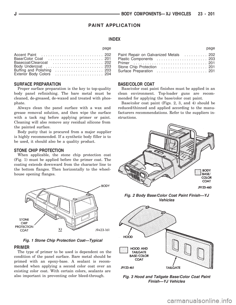
STONE CHIP PROTECTION
When applicable, the stone chip protection coat
(Fig. 1) must be applied before the primer coat. The
coating extends downward from the character line to
the bottom flanges. Then horizontally to the wheel-
house opening flanges.
PRIMER
The type of primer to be used is dependent on the
condition of the panel surface. Bare metal should be
primed with an epoxy-base. A sealant is recom-
mended when applying a second color coat over an
existing color coat. With certain colors, sealants are
also important in preventing color bleed-through.
BASE/COLOR COAT
Base/color coat paint finishes must be applied in an
clean environment. Top-loader guns are recom-
mended for applying the base/color coat paint.
Base/color coat paint (Figs. 2, 3, and 4) should be
reduced/thinned and applied according to the manu-
facturers recommendations. Refer to the suppliers in-
structions.
Fig. 2 Body Base/Color Coat Paint FinishÐYJ
Vehicles
Fig. 3 Hood and Tailgate Base/Color Coat Paint
FinishÐYJ Vehicles
Fig. 1 Stone Chip Protection CoatÐTypical
JBODY COMPONENTSÐXJ VEHICLES 23 - 201
Page 1657 of 1784
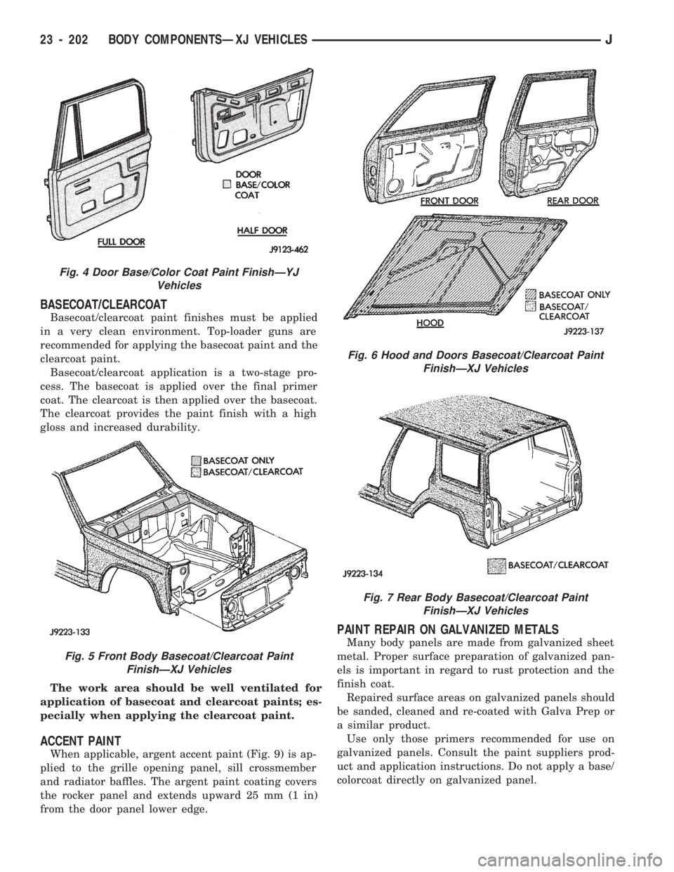
BASECOAT/CLEARCOAT
Basecoat/clearcoat paint finishes must be applied
in a very clean environment. Top-loader guns are
recommended for applying the basecoat paint and the
clearcoat paint.
Basecoat/clearcoat application is a two-stage pro-
cess. The basecoat is applied over the final primer
coat. The clearcoat is then applied over the basecoat.
The clearcoat provides the paint finish with a high
gloss and increased durability.
The work area should be well ventilated for
application of basecoat and clearcoat paints; es-
pecially when applying the clearcoat paint.
ACCENT PAINT
When applicable, argent accent paint (Fig. 9) is ap-
plied to the grille opening panel, sill crossmember
and radiator baffles. The argent paint coating covers
the rocker panel and extends upward 25 mm (1 in)
from the door panel lower edge.
PAINT REPAIR ON GALVANIZED METALS
Many body panels are made from galvanized sheet
metal. Proper surface preparation of galvanized pan-
els is important in regard to rust protection and the
finish coat.
Repaired surface areas on galvanized panels should
be sanded, cleaned and re-coated with Galva Prep or
a similar product.
Use only those primers recommended for use on
galvanized panels. Consult the paint suppliers prod-
uct and application instructions. Do not apply a base/
colorcoat directly on galvanized panel.
Fig. 4 Door Base/Color Coat Paint FinishÐYJ
Vehicles
Fig. 5 Front Body Basecoat/Clearcoat Paint
FinishÐXJ Vehicles
Fig. 6 Hood and Doors Basecoat/Clearcoat Paint
FinishÐXJ Vehicles
Fig. 7 Rear Body Basecoat/Clearcoat Paint
FinishÐXJ Vehicles
23 - 202 BODY COMPONENTSÐXJ VEHICLESJ
Page 1658 of 1784
BUFFING AND POLISHING
Minor paint defects in a base/colorcoat can fre-
quently be removed by light sanding, buffing and
polishing. Wet sand the defect with 600 grit paper
soaked in mineral spirits.
Buff the surface area with a fine grade buffing
compound. Finish the repair with a quality polishing
compound to blend and restore the gloss.
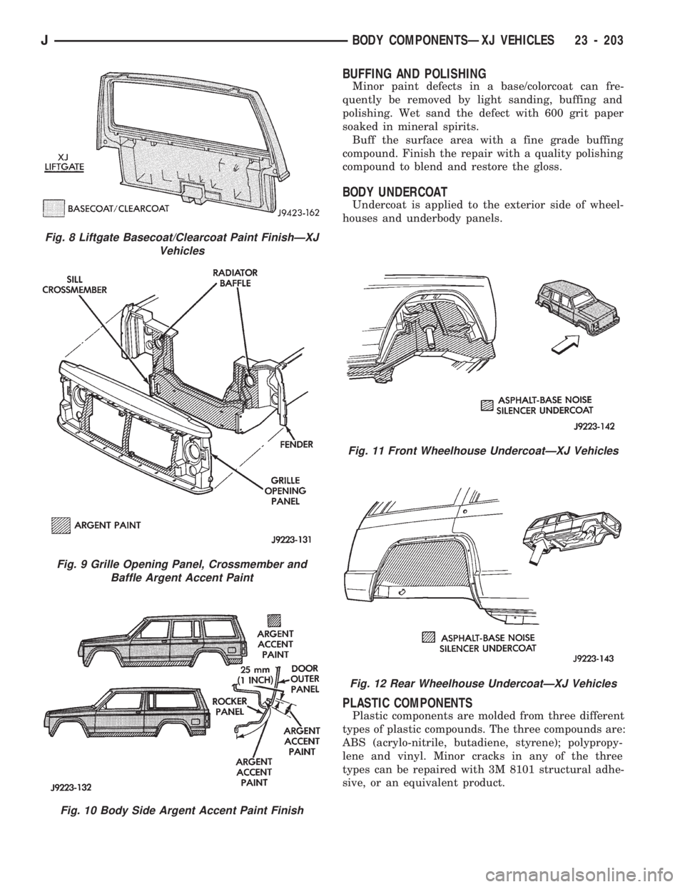
BODY UNDERCOAT
Undercoat is applied to the exterior side of wheel-
houses and underbody panels.
PLASTIC COMPONENTS
Plastic components are molded from three different
types of plastic compounds. The three compounds are:
ABS (acrylo-nitrile, butadiene, styrene); polypropy-
lene and vinyl. Minor cracks in any of the three
types can be repaired with 3M 8101 structural adhe-
sive, or an equivalent product.
Fig. 8 Liftgate Basecoat/Clearcoat Paint FinishÐXJ
Vehicles
Fig. 9 Grille Opening Panel, Crossmember and
Baffle Argent Accent Paint
Fig. 10 Body Side Argent Accent Paint Finish
Fig. 11 Front Wheelhouse UndercoatÐXJ Vehicles
Fig. 12 Rear Wheelhouse UndercoatÐXJ Vehicles
JBODY COMPONENTSÐXJ VEHICLES 23 - 203
Page 1659 of 1784
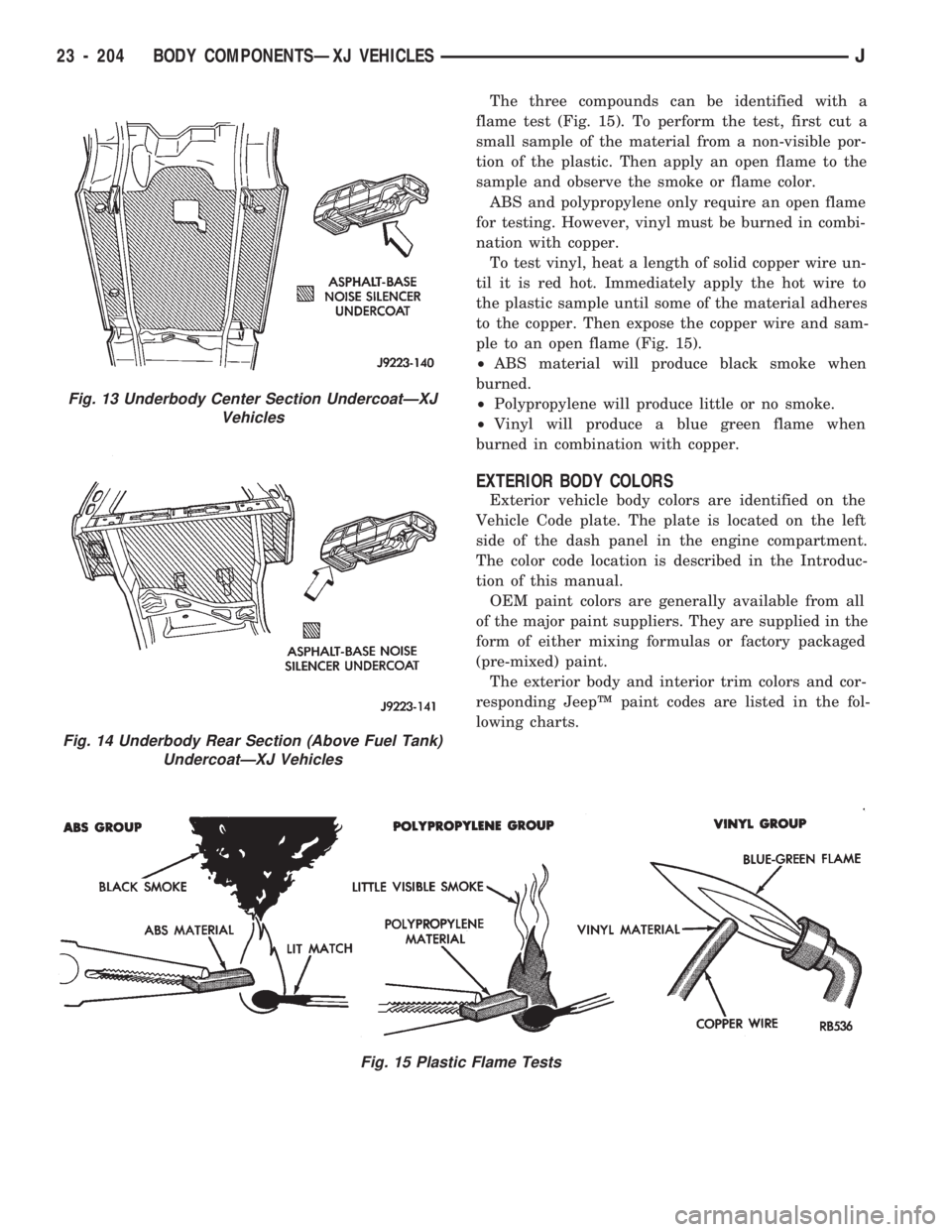
The three compounds can be identified with a
flame test (Fig. 15). To perform the test, first cut a
small sample of the material from a non-visible por-
tion of the plastic. Then apply an open flame to the
sample and observe the smoke or flame color.
ABS and polypropylene only require an open flame
for testing. However, vinyl must be burned in combi-
nation with copper.
To test vinyl, heat a length of solid copper wire un-
til it is red hot. Immediately apply the hot wire to
the plastic sample until some of the material adheres
to the copper. Then expose the copper wire and sam-
ple to an open flame (Fig. 15).
²ABS material will produce black smoke when
burned.
²Polypropylene will produce little or no smoke.
²Vinyl will produce a blue green flame when
burned in combination with copper.
EXTERIOR BODY COLORS
Exterior vehicle body colors are identified on the
Vehicle Code plate. The plate is located on the left
side of the dash panel in the engine compartment.
The color code location is described in the Introduc-
tion of this manual.
OEM paint colors are generally available from all
of the major paint suppliers. They are supplied in the
form of either mixing formulas or factory packaged
(pre-mixed) paint.
The exterior body and interior trim colors and cor-
responding JeepŸ paint codes are listed in the fol-
lowing charts.
Fig. 15 Plastic Flame Tests
Fig. 13 Underbody Center Section UndercoatÐXJ
Vehicles
Fig. 14 Underbody Rear Section (Above Fuel Tank)
UndercoatÐXJ Vehicles
23 - 204 BODY COMPONENTSÐXJ VEHICLESJ
Page 1660 of 1784
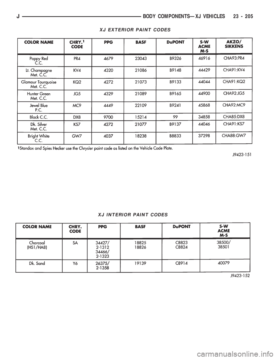
XJ EXTERIOR PAINT CODES
XJ INTERIOR PAINT CODES
JBODY COMPONENTSÐXJ VEHICLES 23 - 205