JEEP CHEROKEE 1994 Service Repair Manual
Manufacturer: JEEP, Model Year: 1994, Model line: CHEROKEE, Model: JEEP CHEROKEE 1994Pages: 1784, PDF Size: 77.09 MB
Page 1691 of 1784
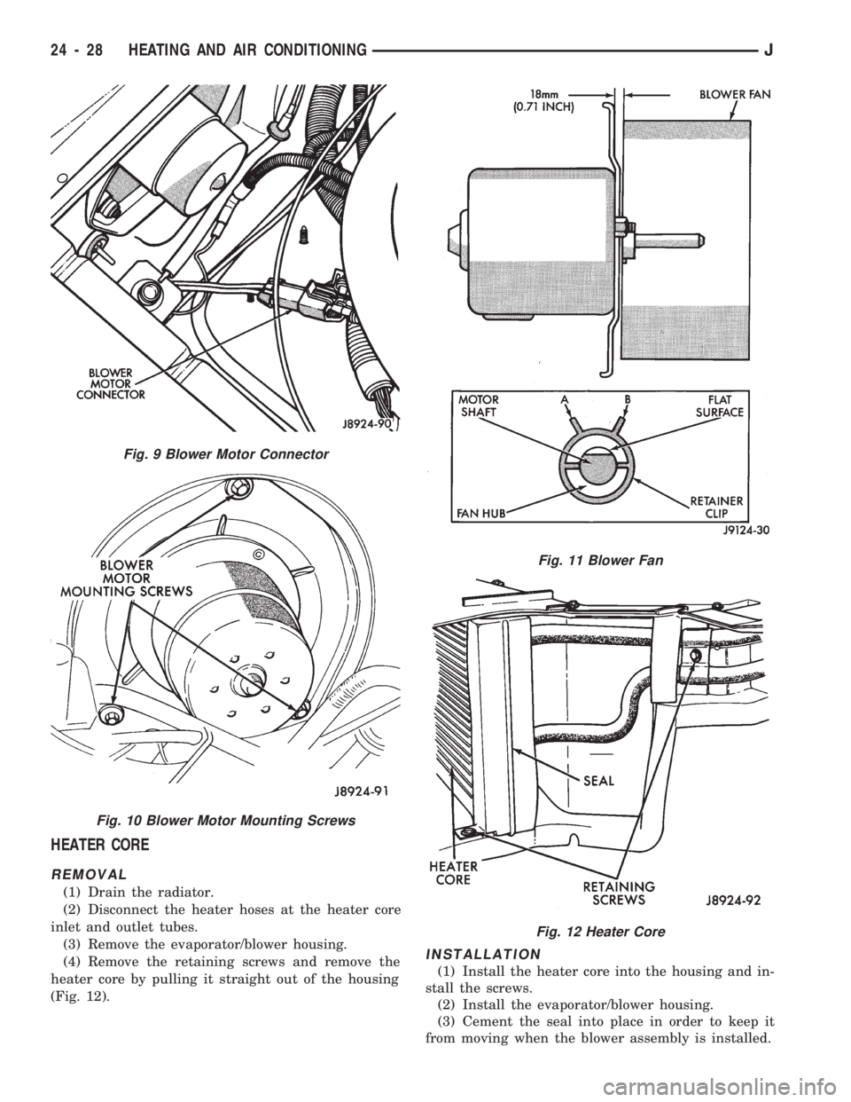
HEATER CORE
REMOVAL
(1) Drain the radiator.
(2) Disconnect the heater hoses at the heater core
inlet and outlet tubes.
(3) Remove the evaporator/blower housing.
(4) Remove the retaining screws and remove the
heater core by pulling it straight out of the housing
(Fig. 12).
INSTALLATION
(1) Install the heater core into the housing and in-
stall the screws.
(2) Install the evaporator/blower housing.
(3) Cement the seal into place in order to keep it
from moving when the blower assembly is installed.
Fig. 9 Blower Motor Connector
Fig. 10 Blower Motor Mounting Screws
Fig. 11 Blower Fan
Fig. 12 Heater Core
24 - 28 HEATING AND AIR CONDITIONINGJ
Page 1692 of 1784
(4) Connect the heater hoses to the heater core.
(5) Fill the cooling system.
HEATER CORE HOUSING REPLACEMENT
(1) Remove the evaporator/blower housing.
(2) Remove the heater core.
(3) Remove the defroster duct.
(4) Disconnect the vacuum hoses from the heater
core housing vacuum motors.
(5) Remove the heater housing retaining nuts in
the engine compartment. Remove the heater core
housing.
(6) Transfer the vacuum motors, etc. to the re-
placement housing.
To install the heater core housing, reverse the re-
moval procedure.
DEFROSTER DUCT REPLACEMENT
REMOVAL
(1) Disconnect negative cable from battery.
(2) If equipped with center console remove the con-
sole as follows:
(a) MANUAL TRANSMISSIONÐRemove shift
knob, boot and bezel.
(b) AUTOMATIC TRANSMISSIONÐRemove
shift handle by pulling up. Remove the shift bezel.
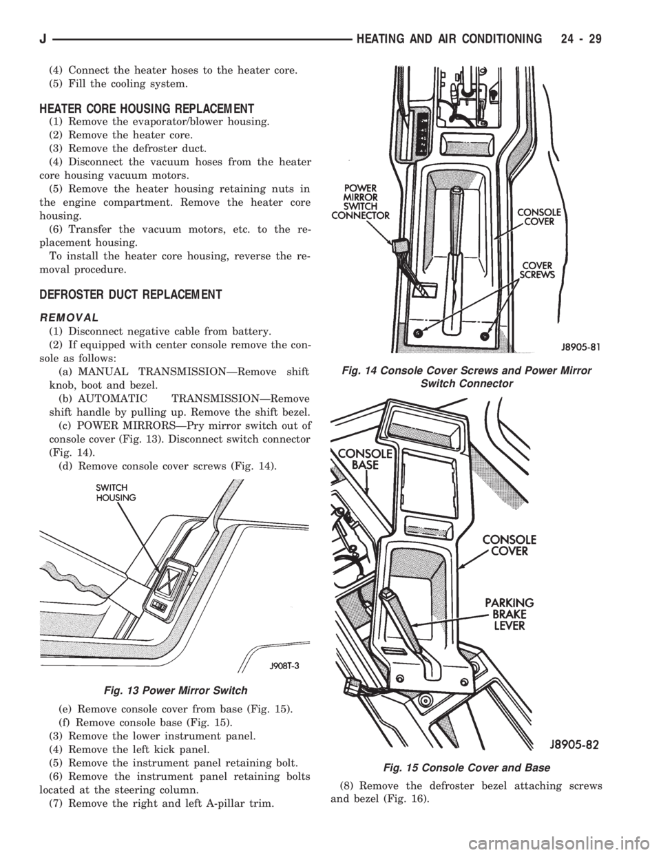
(c) POWER MIRRORSÐPry mirror switch out of
console cover (Fig. 13). Disconnect switch connector
(Fig. 14).
(d) Remove console cover screws (Fig. 14).
(e) Remove console cover from base (Fig. 15).
(f) Remove console base (Fig. 15).
(3) Remove the lower instrument panel.
(4) Remove the left kick panel.
(5) Remove the instrument panel retaining bolt.
(6) Remove the instrument panel retaining bolts
located at the steering column.
(7) Remove the right and left A-pillar trim.(8) Remove the defroster bezel attaching screws
and bezel (Fig. 16).
Fig. 13 Power Mirror Switch
Fig. 14 Console Cover Screws and Power Mirror
Switch Connector
Fig. 15 Console Cover and Base
JHEATING AND AIR CONDITIONING 24 - 29
Page 1693 of 1784
(9) Remove the instrument panel retaining screws.
(10) Lower the steering column.
(11) Pull the instrument panel, approximately 3
inches, away from the dash panel.
(12) Remove the defroster duct retaining screws.
Remove the defroster duct.
(13) Disconnect the hoses.
INSTALLATION
(1) Connect the hoses.
(2) Install the defroster duct. Install the defroster
duct retaining screws.
(3) Position the instrument panel into the dash
panel.
(4) Position the steering column.
(5) Install the instrument panel retaining screws.
(6) Install the defroster bezel attaching screws and
bezel.
(7) Install the right and left A-pillar trim.
(8) Install the instrument panel retaining bolts lo-
cated at the steering column. Tighten the steering
column retaining nuts to 27 NIm (20 ft. lbs.) torque.
(9) Install and tighten the instrument panel re-
taining bolt.
(10) Install the left kick panel.
(11) Install the lower instrument panel.
(12) If equipped with center console, install the
console as follows:
(a) Install console base.
(b) Install console cover to base.
(c) Install and tighten console cover screws.
(d) POWER MIRRORSÐSnap mirror switch into
the console cover. Connect switch connector.
(e) MANUAL TRANSMISSIONÐInstall shift
knob, boot and bezel.(f) AUTOMATIC TRANSMISSIONÐInstall the
shift bezel. Install shift handle by pushing down.
(13) Connect negative cable to battery.
HEATER CONTROL CABLE REPLACEMENT
(1) Remove the heater control panel.
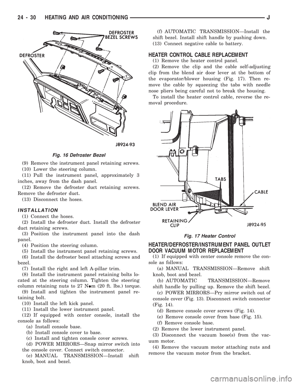
(2) Remove the clip and the cable self-adjusting
clip from the blend air door lever at the bottom of
the evaporator/blower housing (Fig. 17). Then re-
move the cable by squeezing the tabs with needle
nose pliers being careful not to break the housing.
To install the heater control cable, reverse the re-
moval procedure.
HEATER/DEFROSTER/INSTRUMENT PANEL OUTLET
DOOR VACUUM MOTOR REPLACEMENT
(1) If equipped with center console remove the con-
sole as follows:
(a) MANUAL TRANSMISSIONÐRemove shift
knob, boot and bezel.
(b) AUTOMATIC TRANSMISSIONÐRemove
shift handle by pulling up. Remove the shift bezel.
(c) POWER MIRRORSÐPry mirror switch out of
console cover (Fig. 13). Disconnect switch connector
(Fig. 14).
(d) Remove console cover screws (Fig. 14).
(e) Remove console cover from base (Fig. 15).
(f) Remove console base.
(2) Remove the lower instrument panel.
(3) Disconnect the vacuum hose(s) from the vac-
uum motor.
(4) Remove the vacuum motor attaching nuts and
remove the vacuum motor from the bracket.
Fig. 16 Defroster Bezel
Fig. 17 Heater Control
24 - 30 HEATING AND AIR CONDITIONINGJ
Page 1694 of 1784
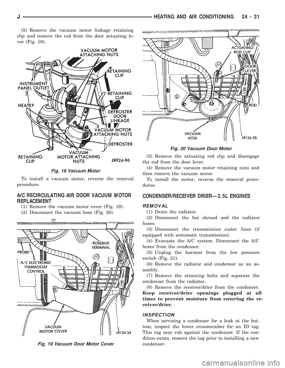
(5) Remove the vacuum motor linkage retaining
clip and remove the rod from the door actuating le-
ver (Fig. 18).
To install a vacuum motor, reverse the removal
procedure.
A/C RECIRCULATING AIR DOOR VACUUM MOTOR
REPLACEMENT
(1) Remove the vacuum motor cover (Fig. 19).
(2) Disconnect the vacuum hose (Fig. 20).(3) Remove the actuating rod clip and disengage
the rod from the door lever.
(4) Remove the vacuum motor retaining nuts and
then remove the vacuum motor.
To install the motor, reverse the removal proce-
dures.
CONDENSER/RECEIVER DRIERÐ2.5L ENGINES
REMOVAL
(1) Drain the radiator.
(2) Disconnect the fan shroud and the radiator
hoses.
(3) Disconnect the transmission cooler lines (if
equipped with automatic transmission).
(4) Evacuate the A/C system. Disconnect the A/C
hoses from the condenser.
(5) Unplug the harness from the low pressure
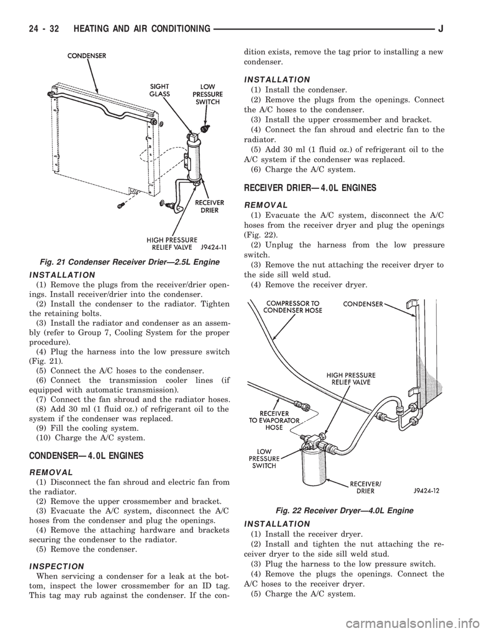
switch (Fig. 21).
(6) Remove the radiator and condenser as an as-
sembly.
(7) Remove the retaining bolts and separate the
condenser from the radiator.
(8) Remove the receiver/drier from the condenser.
Keep receiver/drier openings plugged at all
times to prevent moisture from entering the re-
ceiver/drier.
INSPECTION
When servicing a condenser for a leak at the bot-
tom, inspect the lower crossmember for an ID tag.
This tag may rub against the condenser. If the con-
dition exists, remove the tag prior to installing a new
condenser.
Fig. 18 Vacuum Motor
Fig. 19 Vacuum Door Motor Cover
Fig. 20 Vacuum Door Motor
JHEATING AND AIR CONDITIONING 24 - 31
Page 1695 of 1784
INSTALLATION
(1) Remove the plugs from the receiver/drier open-
ings. Install receiver/drier into the condenser.
(2) Install the condenser to the radiator. Tighten
the retaining bolts.
(3) Install the radiator and condenser as an assem-
bly (refer to Group 7, Cooling System for the proper
procedure).
(4) Plug the harness into the low pressure switch
(Fig. 21).
(5) Connect the A/C hoses to the condenser.
(6) Connect the transmission cooler lines (if
equipped with automatic transmission).
(7) Connect the fan shroud and the radiator hoses.
(8) Add 30 ml (1 fluid oz.) of refrigerant oil to the
system if the condenser was replaced.
(9) Fill the cooling system.
(10) Charge the A/C system.
CONDENSERÐ4.0L ENGINES
REMOVAL
(1) Disconnect the fan shroud and electric fan from
the radiator.
(2) Remove the upper crossmember and bracket.
(3) Evacuate the A/C system, disconnect the A/C
hoses from the condenser and plug the openings.
(4) Remove the attaching hardware and brackets
securing the condenser to the radiator.
(5) Remove the condenser.
INSPECTION
When servicing a condenser for a leak at the bot-
tom, inspect the lower crossmember for an ID tag.
This tag may rub against the condenser. If the con-dition exists, remove the tag prior to installing a new
condenser.
INSTALLATION
(1) Install the condenser.
(2) Remove the plugs from the openings. Connect
the A/C hoses to the condenser.
(3) Install the upper crossmember and bracket.
(4) Connect the fan shroud and electric fan to the
radiator.
(5) Add 30 ml (1 fluid oz.) of refrigerant oil to the
A/C system if the condenser was replaced.
(6) Charge the A/C system.
RECEIVER DRIERÐ4.0L ENGINES
REMOVAL
(1) Evacuate the A/C system, disconnect the A/C
hoses from the receiver dryer and plug the openings
(Fig. 22).
(2) Unplug the harness from the low pressure
switch.
(3) Remove the nut attaching the receiver dryer to
the side sill weld stud.
(4) Remove the receiver dryer.
INSTALLATION
(1) Install the receiver dryer.
(2) Install and tighten the nut attaching the re-
ceiver dryer to the side sill weld stud.
(3) Plug the harness to the low pressure switch.
(4) Remove the plugs the openings. Connect the
A/C hoses to the receiver dryer.
(5) Charge the A/C system.
Fig. 21 Condenser Receiver DrierÐ2.5L Engine
Fig. 22 Receiver DryerÐ4.0L Engine
24 - 32 HEATING AND AIR CONDITIONINGJ
Page 1696 of 1784
EVAPORATOR/BLOWER HOUSING
REMOVAL
(1) Disconnect negative cable from battery.
(2) Discharge the A/C system as described in this
section and disconnect the A/C hoses from the expan-
sion valve.
(3) Disconnect the blower motor wires and the vent
tube.
(4) If equipped with center console remove the con-
sole as follows:
(a) MANUAL TRANSMISSIONÐRemove shift
knob, boot and bezel.
(b) AUTOMATIC TRANSMISSIONÐRemove
shift handle by pulling up. Remove the shift bezel.
(c) POWER MIRRORSÐPry mirror switch out of
console cover (Fig. 13) and disconnect switch con-
nector (Fig. 14).
(d) Remove console cover screws (Fig. 14).
(e) Remove console cover from base (Fig. 15).
(f) Remove console base.
(5) Remove the lower instrument panel.
(6) Disconnect the electrical connections at the
blower motor resistors and the A/C thermostat. Dis-
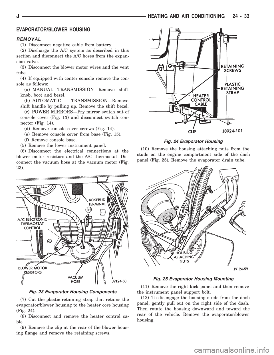
connect the vacuum hose at the vacuum motor (Fig.
23).
(7) Cut the plastic retaining strap that retains the
evaporator/blower housing to the heater core housing
(Fig. 24).
(8) Disconnect and remove the heater control ca-
ble.
(9) Remove the clip at the rear of the blower hous-
ing flange and remove the retaining screws.(10) Remove the housing attaching nuts from the
studs on the engine compartment side of the dash
panel (Fig. 25). Remove the evaporator drain tube.
(11) Remove the right kick panel and then remove
the instrument panel support bolt.
(12) To disengage the housing studs from the dash
panel, gently pull out on the right side of the dash.
Then rotate the housing downward and toward the
rear of the vehicle. Remove the evaporator/blower
housing.
Fig. 23 Evaporator Housing Components
Fig. 24 Evaporator Housing
Fig. 25 Evaporator Housing Mounting
JHEATING AND AIR CONDITIONING 24 - 33
Page 1697 of 1784
INSTALLATION
(1) Position the evaporator/blower housing into
place, being sure to line up the housings using the
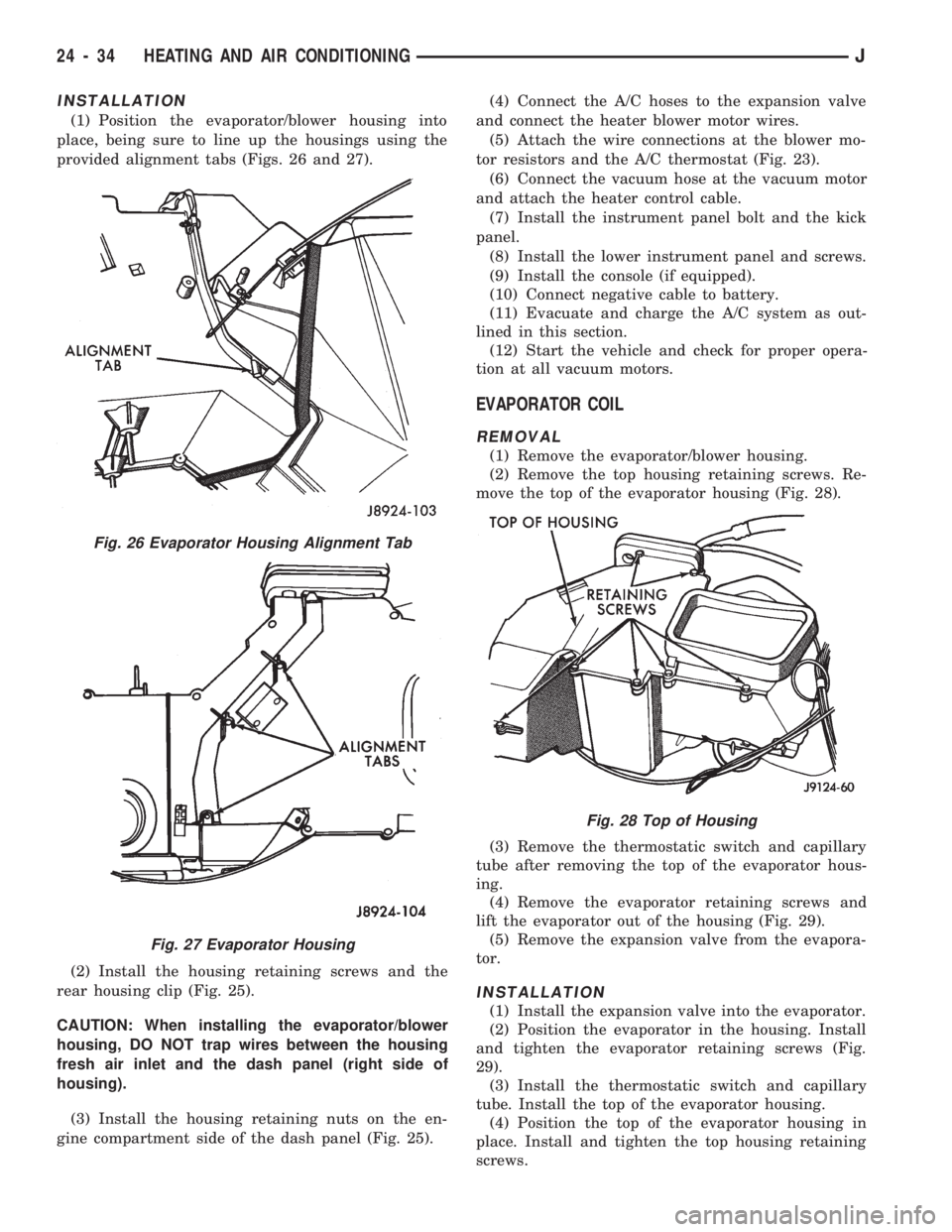
provided alignment tabs (Figs. 26 and 27).
(2) Install the housing retaining screws and the
rear housing clip (Fig. 25).
CAUTION: When installing the evaporator/blower
housing, DO NOT trap wires between the housing
fresh air inlet and the dash panel (right side of
housing).
(3) Install the housing retaining nuts on the en-
gine compartment side of the dash panel (Fig. 25).(4) Connect the A/C hoses to the expansion valve
and connect the heater blower motor wires.
(5) Attach the wire connections at the blower mo-
tor resistors and the A/C thermostat (Fig. 23).
(6) Connect the vacuum hose at the vacuum motor
and attach the heater control cable.
(7) Install the instrument panel bolt and the kick
panel.
(8) Install the lower instrument panel and screws.
(9) Install the console (if equipped).
(10) Connect negative cable to battery.
(11) Evacuate and charge the A/C system as out-
lined in this section.
(12) Start the vehicle and check for proper opera-
tion at all vacuum motors.
EVAPORATOR COIL
REMOVAL
(1) Remove the evaporator/blower housing.
(2) Remove the top housing retaining screws. Re-
move the top of the evaporator housing (Fig. 28).
(3) Remove the thermostatic switch and capillary
tube after removing the top of the evaporator hous-
ing.
(4) Remove the evaporator retaining screws and
lift the evaporator out of the housing (Fig. 29).
(5) Remove the expansion valve from the evapora-
tor.
INSTALLATION
(1) Install the expansion valve into the evaporator.
(2) Position the evaporator in the housing. Install
and tighten the evaporator retaining screws (Fig.
29).
(3) Install the thermostatic switch and capillary
tube. Install the top of the evaporator housing.
(4) Position the top of the evaporator housing in
place. Install and tighten the top housing retaining
screws.
Fig. 26 Evaporator Housing Alignment Tab
Fig. 27 Evaporator Housing
Fig. 28 Top of Housing
24 - 34 HEATING AND AIR CONDITIONINGJ
Page 1698 of 1784
(5) Install the evaporator/blower housing.
(6) Add 30 ml (1 fluid oz.) of refrigerant oil to the
air conditioning system if the evaporator was re-
placed.
EXPANSION (H) VALVE
REMOVAL
(1) Discharge the A/C system.
(2) Remove the coolant bottle and bracket.
(3) Disconnect A/C hoses from the expansion valve
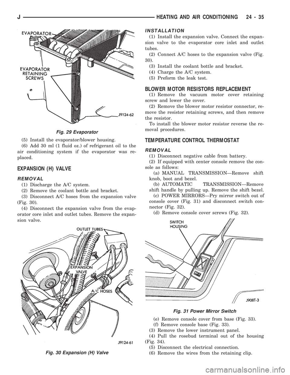
(Fig. 30).
(4) Disconnect the expansion valve from the evap-
orator core inlet and outlet tubes. Remove the expan-
sion valve.
INSTALLATION
(1) Install the expansion valve. Connect the expan-
sion valve to the evaporator core inlet and outlet
tubes.
(2) Connect A/C hoses to the expansion valve (Fig.
30).
(3) Install the coolant bottle and bracket.
(4) Charge the A/C system.
(5) Preform the leak test.
BLOWER MOTOR RESISTORS REPLACEMENT
(1) Remove the vacuum motor cover retaining
screw and lower the cover.
(2) Remove the blower motor resistor connector, re-
move the resistor retaining screws, and then remove
the resistor.
To install the blower motor resistor reverse the re-
moval procedures.
TEMPERATURE CONTROL THERMOSTAT
REMOVAL
(1) Disconnect negative cable from battery.
(2) If equipped with center console remove the con-
sole as follows:
(a) MANUAL TRANSMISSIONÐRemove shift
knob, boot and bezel.
(b) AUTOMATIC TRANSMISSIONÐRemove
shift handle by pulling up. Remove the shift bezel.
(c) POWER MIRRORSÐPry mirror switch out of
console cover (Fig. 31) and disconnect switch con-
nector (Fig. 32).
(d) Remove console cover screws (Fig. 32).
(e) Remove console cover from base (Fig. 33).
(f) Remove console base (Fig. 33).
(3) Remove the lower instrument panel.
(4) Pull the rosebud terminal out of the housing
(Fig. 34).
(5) Disconnect the electrical connection.
(6) Remove the wires from the retaining clip.
Fig. 29 Evaporator
Fig. 30 Expansion (H) Valve
Fig. 31 Power Mirror Switch
JHEATING AND AIR CONDITIONING 24 - 35
Page 1699 of 1784
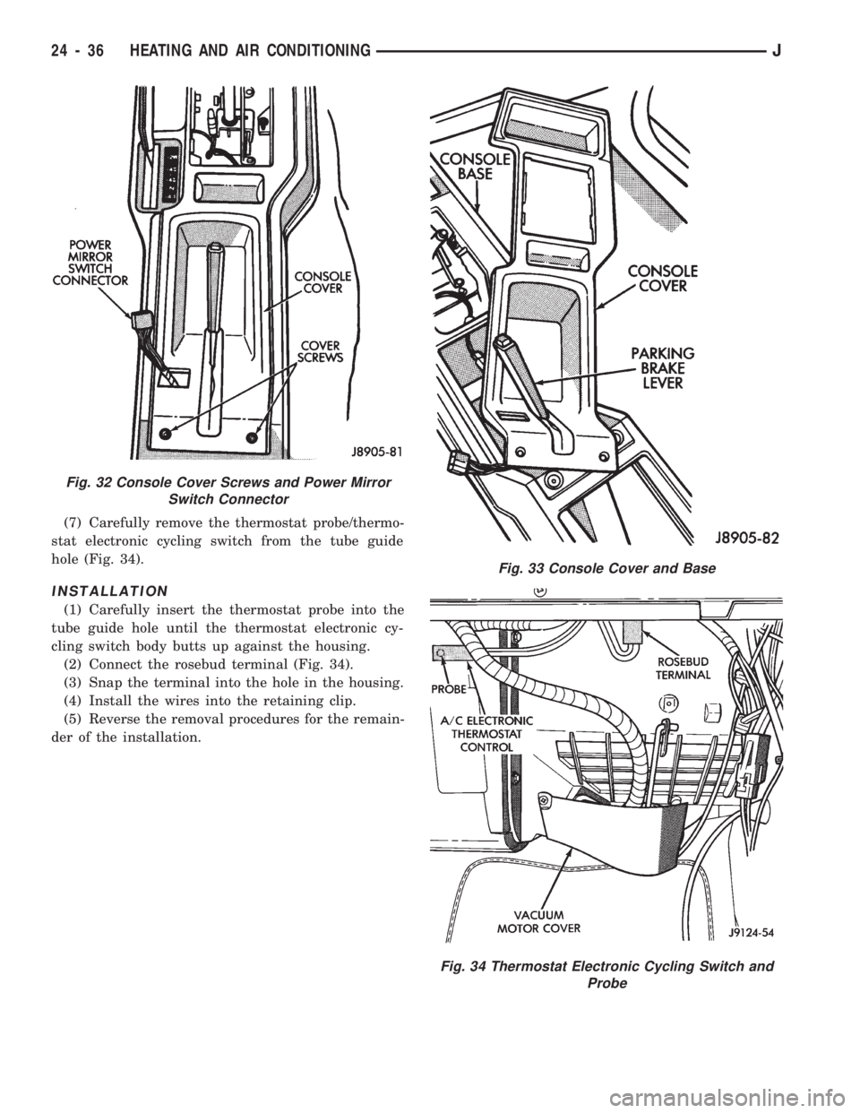
(7) Carefully remove the thermostat probe/thermo-
stat electronic cycling switch from the tube guide
hole (Fig. 34).
INSTALLATION
(1) Carefully insert the thermostat probe into the
tube guide hole until the thermostat electronic cy-
cling switch body butts up against the housing.
(2) Connect the rosebud terminal (Fig. 34).
(3) Snap the terminal into the hole in the housing.
(4) Install the wires into the retaining clip.
(5) Reverse the removal procedures for the remain-
der of the installation.
Fig. 32 Console Cover Screws and Power Mirror
Switch Connector
Fig. 33 Console Cover and Base
Fig. 34 Thermostat Electronic Cycling Switch and
Probe
24 - 36 HEATING AND AIR CONDITIONINGJ
Page 1700 of 1784
CLIMATE CONTROL SYSTEMÐYJ VEHICLES
INDEX
page page
A/C Blower Motor........................ 43
A/C Condenser.......................... 42
A/C Control Panel........................ 41
Blower Motor (Heating).................... 40
Blower Motor/Air Door Motor Switch Replacement . 39
Defroster Nozzle and Duct................. 40
Description (Air Conditioning)................ 41
Description (Heating)...................... 37
Evaporator and Housing................... 42
Expansion (H) Valve...................... 43Fresh Air Door Vacuum Motor............... 41
Fresh Air Intake Duct..................... 41
Fresh Air Ventilation...................... 39
Heater Control Panel Replacement........... 39
Heater Core and Housing.................. 40
Heater/Defroster Operation................. 37
Receiver-Drier Replacement................ 42
Sight Glass............................. 41
Vent Door Control Cables.................. 39
DESCRIPTION (HEATING)
A blend-air heating system is used in YJ vehicles.
The blend-air system provides a constant flow of en-
gine coolant through the heater core.
The temperature of heated air entering the passen-
ger compartment is controlled by regulating the
quantity of air flow through the heater core. This is
accomplished by blending a controlled amount of un-
heated air from outside the vehicle with heated air
from the heater core.
HEATER/DEFROSTER OPERATION
The heater core is connected to the engine cooling
system. It operates on the circulation of heated en-
gine coolant through the core and a supply of fresh
air drawn in through the intake grille on the cowl.
Engine coolant flows through the heater core at all
times.
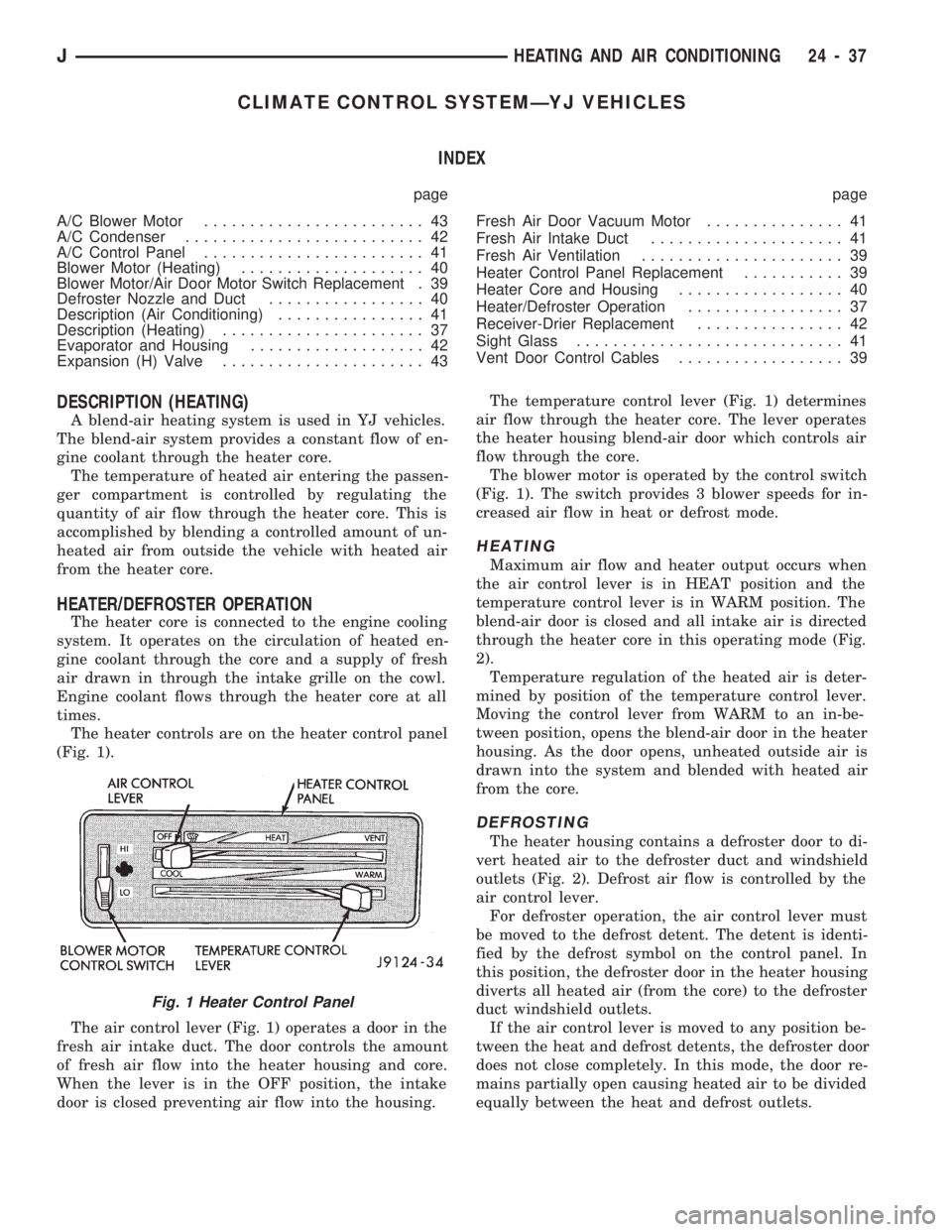
The heater controls are on the heater control panel
(Fig. 1).
The air control lever (Fig. 1) operates a door in the
fresh air intake duct. The door controls the amount
of fresh air flow into the heater housing and core.
When the lever is in the OFF position, the intake
door is closed preventing air flow into the housing.The temperature control lever (Fig. 1) determines
air flow through the heater core. The lever operates
the heater housing blend-air door which controls air
flow through the core.
The blower motor is operated by the control switch
(Fig. 1). The switch provides 3 blower speeds for in-
creased air flow in heat or defrost mode.
HEATING
Maximum air flow and heater output occurs when
the air control lever is in HEAT position and the
temperature control lever is in WARM position. The
blend-air door is closed and all intake air is directed
through the heater core in this operating mode (Fig.
2).
Temperature regulation of the heated air is deter-
mined by position of the temperature control lever.
Moving the control lever from WARM to an in-be-
tween position, opens the blend-air door in the heater
housing. As the door opens, unheated outside air is
drawn into the system and blended with heated air
from the core.
DEFROSTING
The heater housing contains a defroster door to di-
vert heated air to the defroster duct and windshield
outlets (Fig. 2). Defrost air flow is controlled by the
air control lever.
For defroster operation, the air control lever must
be moved to the defrost detent. The detent is identi-
fied by the defrost symbol on the control panel. In
this position, the defroster door in the heater housing
diverts all heated air (from the core) to the defroster
duct windshield outlets.
If the air control lever is moved to any position be-
tween the heat and defrost detents, the defroster door
does not close completely. In this mode, the door re-
mains partially open causing heated air to be divided
equally between the heat and defrost outlets.
Fig. 1 Heater Control Panel
JHEATING AND AIR CONDITIONING 24 - 37