JEEP CHEROKEE 1994 Service Repair Manual
Manufacturer: JEEP, Model Year: 1994, Model line: CHEROKEE, Model: JEEP CHEROKEE 1994Pages: 1784, PDF Size: 77.09 MB
Page 1661 of 1784
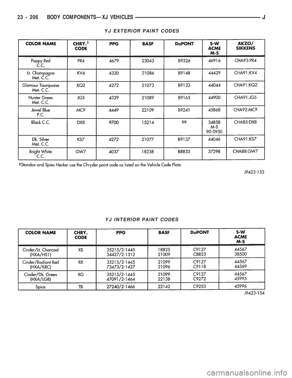
YJ EXTERIOR PAINT CODES
YJ INTERIOR PAINT CODES
23 - 206 BODY COMPONENTSÐXJ VEHICLESJ
Page 1662 of 1784
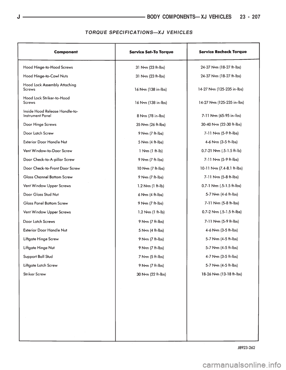
TORQUE SPECIFICATIONSÐXJ VEHICLES
JBODY COMPONENTSÐXJ VEHICLES 23 - 207
Page 1663 of 1784
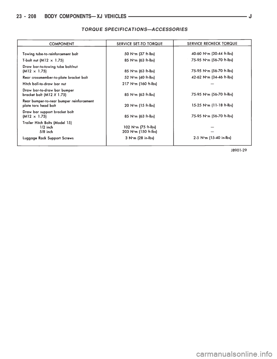
TORQUE SPECIFICATIONSÐACCESSORIES
23 - 208 BODY COMPONENTSÐXJ VEHICLESJ
Page 1664 of 1784
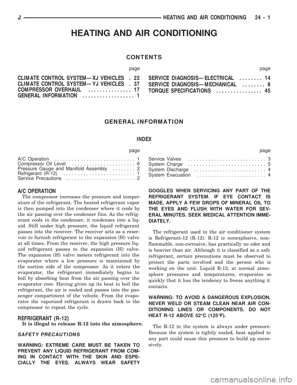
HEATING AND AIR CONDITIONING
CONTENTS
page page
CLIMATE CONTROL SYSTEMÐXJ VEHICLES . 22
CLIMATE CONTROL SYSTEMÐYJ VEHICLES . 37
COMPRESSOR OVERHAUL............... 17
GENERAL INFORMATION.................. 1SERVICE DIAGNOSISÐELECTRICAL........ 14
SERVICE DIAGNOSISÐMECHANICAL........ 8
TORQUE SPECIFICATIONS................ 45
GENERAL INFORMATION
INDEX
page page
A/C Operation............................ 1
Compressor Oil Level...................... 6
Pressure Gauge and Manifold Assembly........ 2
Refrigerant (R-12)......................... 1
Service Precautions........................ 2Service Valves........................... 3
System Charge........................... 5
System Discharge......................... 4
System Evacuation........................ 4
A/C OPERATION
The compressor increases the pressure and temper-
ature of the refrigerant. The heated refrigerant vapor
is then pumped into the condenser where it cools by
the air passing over the condenser fins. As the refrig-
erant cools in the condenser, it condenses into a liq-
uid. Still under high pressure, the liquid refrigerant
passes into the receiver. The receiver acts as a reser-
voir to furnish refrigerant to the expansion (H) valve
at all times. From the receiver, the high pressure liq-
uid refrigerant passes to the expansion (H) valve.
The expansion (H) valve meters refrigerant into the
evaporator where a low pressure is maintained by
the suction side of the compressor. As it enters the
evaporator, the refrigerant immediately begins to
boil by absorbing heat from the air passing over the
evaporator core. Having given up its heat to boil the
refrigerant, the air is cooled and passes into the pas-
senger compartment of the vehicle. From the evapo-
rator the vaporized refrigerant is drawn back to the
compressor to repeat the cycle.
REFRIGERANT (R-12)
It is illegal to release R-12 into the atmosphere.
SAFETY PRECAUTIONS
WARNING: EXTREME CARE MUST BE TAKEN TO
PREVENT ANY LIQUID REFRIGERANT FROM COM-
ING IN CONTACT WITH THE SKIN AND ESPE-
CIALLY THE EYES. ALWAYS WEAR SAFETYGOGGLES WHEN SERVICING ANY PART OF THE
REFRIGERANT SYSTEM. IF EYE CONTACT IS
MADE, APPLY A FEW DROPS OF MINERAL OIL TO
THE EYES AND FLUSH WITH WATER FOR SEV-
ERAL MINUTES. SEEK MEDICAL ATTENTION IMME-
DIATELY.
The refrigerant used in the air conditioner system
is Refrigerant-12 (R-12). R-12 is nonexplosive, non-
flammable, non-corrosive, has practically no odor and
is heavier than air. Although it is classified as a safe
refrigerant, certain precautions must be observed to
protect the parts involved and the person who is
working on the unit. Liquid R-12, at normal atmo-
sphere pressures and temperatures, evaporates so
quickly that it has the tendency to freeze anything it
contacts.
WARNING: TO AVOID A DANGEROUS EXPLOSION,
NEVER WELD OR STEAM CLEAN NEAR AIR CON-
DITIONING LINES OR COMPONENTS. DO NOT
HEAT R-12 ABOVE 52ÉC (125ÉF).
The R-12 in the system is always under pressure.
Because the system is tightly sealed, heat applied to
any part could cause this pressure to build up exces-
sively.
JHEATING AND AIR CONDITIONING 24 - 1
Page 1665 of 1784
WARNING: LARGE AMOUNTS OF REFRIGERANT
RELEASED IN A CLOSED WORK AREA WILL DIS-
PLACE THE OXYGEN AND CAUSE SUFFOCATION.
ALWAYS MAINTAIN GOOD VENTILATION SUR-
ROUNDING THE WORK AREA.
R-12 gas, under normal conditions, is non-poison-
ous.
WARNING: THE DISCHARGE OF R-12 GAS NEAR
AN OPEN FLAME CAN PRODUCE A VERY POISON-
OUS GAS CALLED PHOSGENE. PHOSGENE IS
GENERATED WHEN A FLAME-TYPE LEAK DETEC-
TOR IS USED.
CAUTION: When charging an A/C system always
keep the tank in an upright position. If the tank is
on its side or upside down, liquid refrigerant will
enter the system and may damage the compressor.
In most instances when charging or adding refrig-
erant, moderate heat is required to bring the pres-
sure of the refrigerant above the pressure of the
system. A bucket or large pan of hot water, not over
52ÉC (125ÉF), is all the heat required for this pur-
pose. DO NOT heat the refrigerant container with a
blow torch or any other means that would raise the
temperature and pressure above this temperature.
CAUTION: DO NOT allow liquid refrigerant to touch
bright metal. Refrigerant will tarnish bright metal
and chrome surfaces. Refrigerant in combination
with moisture is very corrosive and can cause ex-
tensive damage to all metal surfaces.
Avoid splashing the refrigerant on any surface.
RECYCLING
(R-12) refrigerant is a chloroflorocarbon (CFC) that
can contribute to the depletion of the ozone layer in
the upper atmosphere. Ozone filters out harmful ra-
diation from the sun. To assist in protecting the
ozone layer, Chrysler Corporation requires that an
(R-12) refrigerant recovery device that meets SAE
standard J1991 be used. Contact an automotive ser-
vice equipment supplier for refrigerant recycling
equipment that is available in your area. Refer to
the operating instructions provided with the recy-
cling equipment for proper operation.
SERVICE PRECAUTIONS
Never open or loosen a connection before discharg-
ing the system refrigerant.
A system which has been opened to replace a com-
ponent or one which has discharged through leakage
must be evacuated before charging.
Immediately after disconnecting a component from
the system, seal the open fittings with a cap or plug.Before disconnecting a component from the system,
clean the outside of the fittings thoroughly.
DO NOT remove the sealing caps from a replace-
ment component until ready to install.
Refrigerant oil will absorb moisture from the atmo-
sphere if left uncapped. DO NOT open an oil con-
tainer until ready to use and install the cap
immediately after using. Store the oil only in a clean
moisture-free container.
Before connecting an open fitting always install a
new seal ring. Coat the fitting and seal with clean
refrigerant oil before connecting.
When installing a refrigerant line avoid sharp
bends. Position the line away from the exhaust or
any sharp edges which may chafe the line.
Tighten fittings only to the specified torque. The
copper and aluminum fittings used in the A/C system
will not tolerate over tightening.
When disconnecting a fitting use a wrench on both
halves of the fitting to prevent twisting of the refrig-
erant lines or tubes.
DO NOT open a refrigerant system or uncap a re-
placement component unless it is as close as possible
to room temperature. This will prevent condensation
from forming inside of a component which is cooler
than the surrounding air.
Keep service tools and the work area clean. Con-
tamination of A/C system through careless work hab-
its must be avoided.
PRESSURE GAUGE AND MANIFOLD ASSEMBLY
Pressure Gauge and Manifold Assembly Tool
C-3740-B (Fig. 1) is the most important tool used to
service the air conditioning system. The gauge as-
sembly is used to determine:
²System high side gauge pressures
²System low side gauge pressures
²The correct refrigerant charge
²System diagnosis
It is designed to provide simultaneous high and low
side pressure indications, because these pressures
must be compared to determine the correct system
operation.
LOW SIDE GAUGE
The low side gauge is a compound gauge, which
means that it will register both pressure and vacuum
(Fig. 1). The compound gauge is calibrated 0-1034
kPa (0-150 psi) pressure and 0-760 mm (0-30 in.) of
mercury vacuum. It is connected to the suction ser-
vice valve to check the low side pressure or vacuum.
HIGH SIDE GAUGE
The high side gauge is used to check the pressure
in the discharge side of the air conditioning system
(Fig. 1).
24 - 2 HEATING AND AIR CONDITIONINGJ
Page 1666 of 1784
MANIFOLD
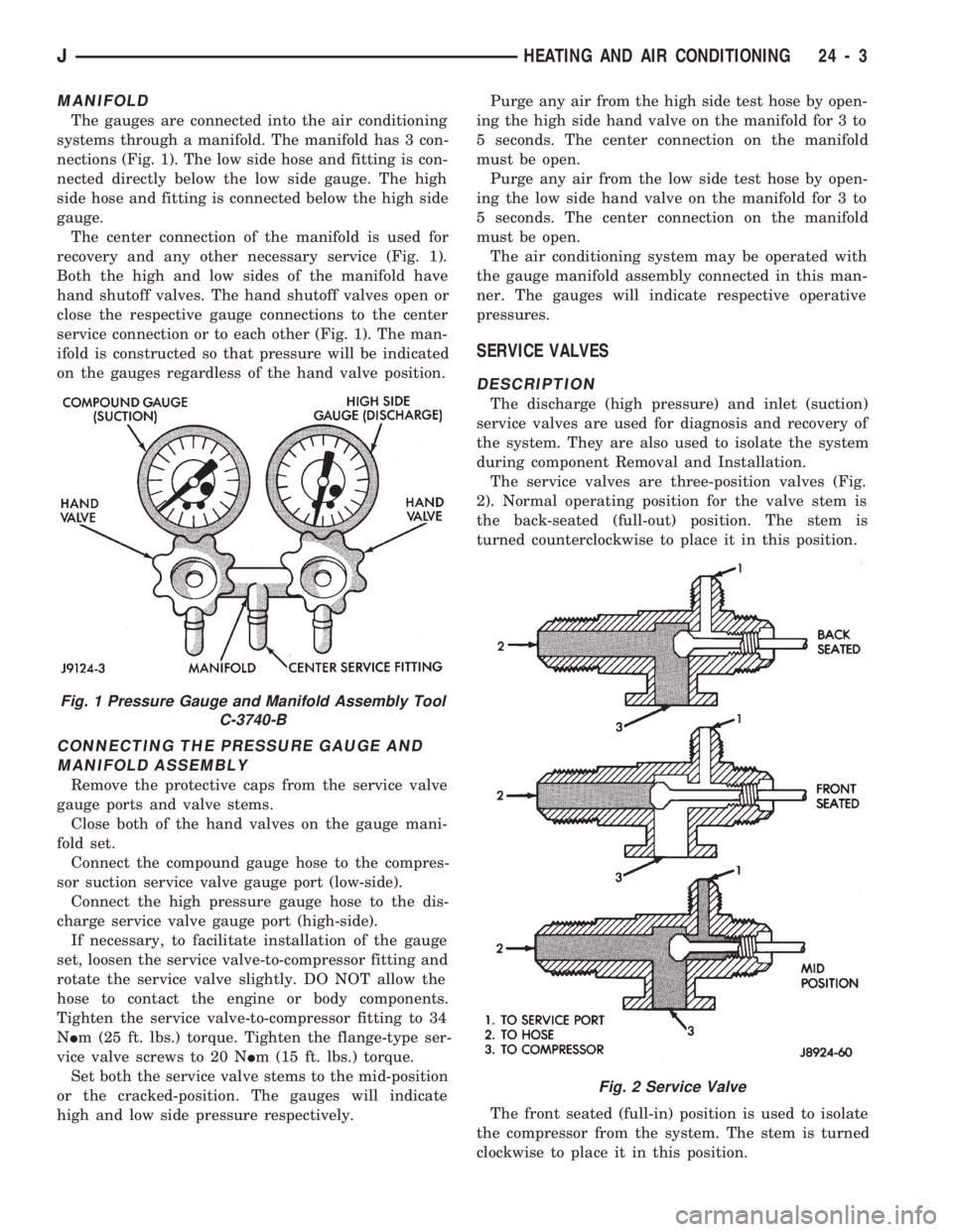
The gauges are connected into the air conditioning
systems through a manifold. The manifold has 3 con-
nections (Fig. 1). The low side hose and fitting is con-
nected directly below the low side gauge. The high
side hose and fitting is connected below the high side
gauge.
The center connection of the manifold is used for
recovery and any other necessary service (Fig. 1).
Both the high and low sides of the manifold have
hand shutoff valves. The hand shutoff valves open or
close the respective gauge connections to the center
service connection or to each other (Fig. 1). The man-
ifold is constructed so that pressure will be indicated
on the gauges regardless of the hand valve position.
CONNECTING THE PRESSURE GAUGE AND
MANIFOLD ASSEMBLY
Remove the protective caps from the service valve
gauge ports and valve stems.
Close both of the hand valves on the gauge mani-
fold set.
Connect the compound gauge hose to the compres-
sor suction service valve gauge port (low-side).
Connect the high pressure gauge hose to the dis-
charge service valve gauge port (high-side).
If necessary, to facilitate installation of the gauge
set, loosen the service valve-to-compressor fitting and
rotate the service valve slightly. DO NOT allow the
hose to contact the engine or body components.
Tighten the service valve-to-compressor fitting to 34
NIm (25 ft. lbs.) torque. Tighten the flange-type ser-
vice valve screws to 20 NIm (15 ft. lbs.) torque.
Set both the service valve stems to the mid-position
or the cracked-position. The gauges will indicate
high and low side pressure respectively.Purge any air from the high side test hose by open-
ing the high side hand valve on the manifold for 3 to
5 seconds. The center connection on the manifold
must be open.
Purge any air from the low side test hose by open-
ing the low side hand valve on the manifold for 3 to
5 seconds. The center connection on the manifold
must be open.
The air conditioning system may be operated with
the gauge manifold assembly connected in this man-
ner. The gauges will indicate respective operative
pressures.
SERVICE VALVES
DESCRIPTION
The discharge (high pressure) and inlet (suction)
service valves are used for diagnosis and recovery of
the system. They are also used to isolate the system
during component Removal and Installation.
The service valves are three-position valves (Fig.
2). Normal operating position for the valve stem is
the back-seated (full-out) position. The stem is
turned counterclockwise to place it in this position.
The front seated (full-in) position is used to isolate
the compressor from the system. The stem is turned
clockwise to place it in this position.
Fig. 1 Pressure Gauge and Manifold Assembly Tool
C-3740-B
Fig. 2 Service Valve
JHEATING AND AIR CONDITIONING 24 - 3
Page 1667 of 1784
In the mid-position the gauge port is open. This po-
sition is used for pressure testing and for recovery of
the system.
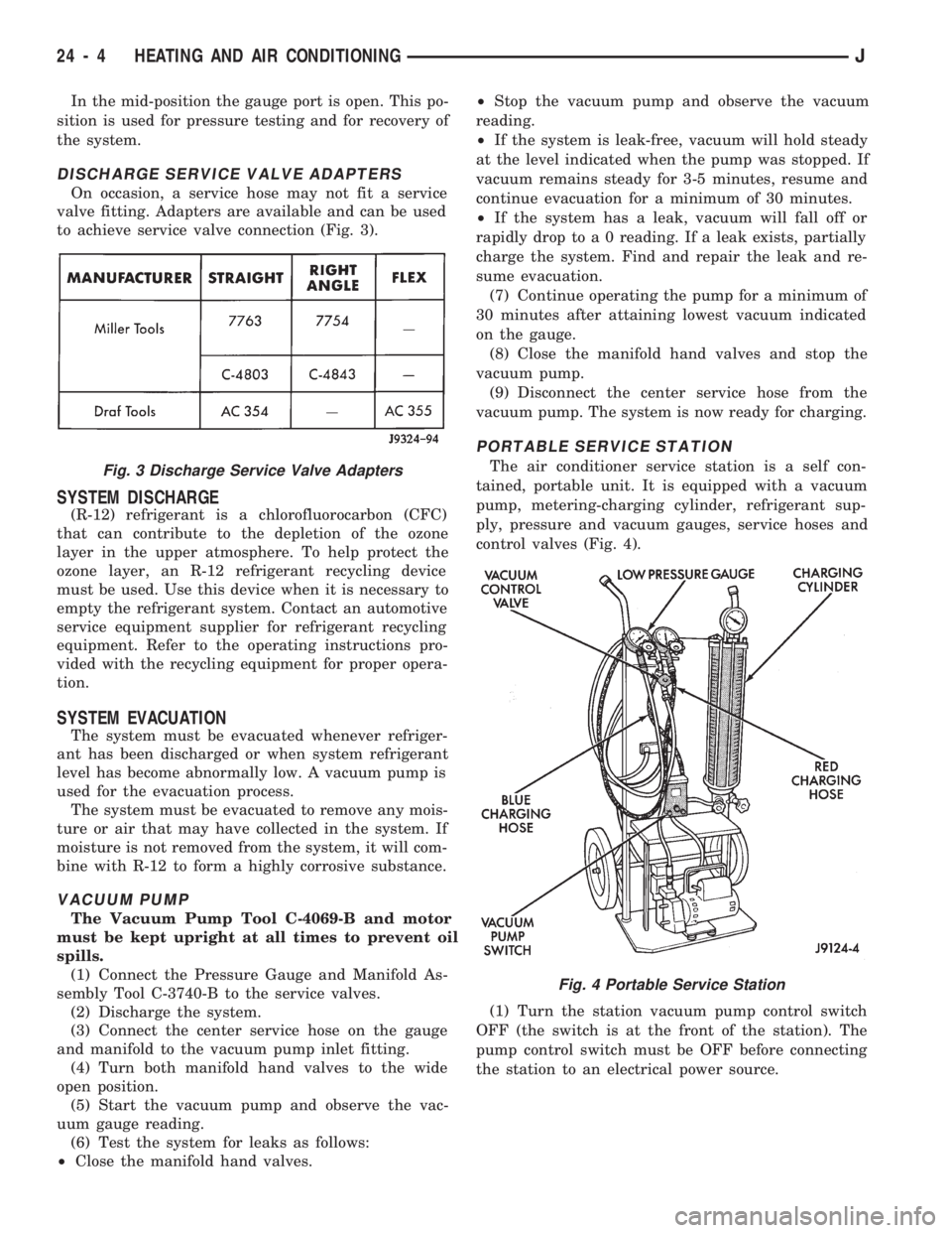
DISCHARGE SERVICE VALVE ADAPTERS
On occasion, a service hose may not fit a service
valve fitting. Adapters are available and can be used
to achieve service valve connection (Fig. 3).
SYSTEM DISCHARGE
(R-12) refrigerant is a chlorofluorocarbon (CFC)
that can contribute to the depletion of the ozone
layer in the upper atmosphere. To help protect the
ozone layer, an R-12 refrigerant recycling device
must be used. Use this device when it is necessary to
empty the refrigerant system. Contact an automotive
service equipment supplier for refrigerant recycling
equipment. Refer to the operating instructions pro-
vided with the recycling equipment for proper opera-
tion.
SYSTEM EVACUATION
The system must be evacuated whenever refriger-
ant has been discharged or when system refrigerant
level has become abnormally low. A vacuum pump is
used for the evacuation process.
The system must be evacuated to remove any mois-
ture or air that may have collected in the system. If
moisture is not removed from the system, it will com-
bine with R-12 to form a highly corrosive substance.
VACUUM PUMP
The Vacuum Pump Tool C-4069-B and motor
must be kept upright at all times to prevent oil
spills.
(1) Connect the Pressure Gauge and Manifold As-
sembly Tool C-3740-B to the service valves.
(2) Discharge the system.
(3) Connect the center service hose on the gauge
and manifold to the vacuum pump inlet fitting.
(4) Turn both manifold hand valves to the wide
open position.
(5) Start the vacuum pump and observe the vac-
uum gauge reading.
(6) Test the system for leaks as follows:
²Close the manifold hand valves.²Stop the vacuum pump and observe the vacuum
reading.
²If the system is leak-free, vacuum will hold steady
at the level indicated when the pump was stopped. If
vacuum remains steady for 3-5 minutes, resume and
continue evacuation for a minimum of 30 minutes.
²If the system has a leak, vacuum will fall off or
rapidly drop to a 0 reading. If a leak exists, partially
charge the system. Find and repair the leak and re-
sume evacuation.
(7) Continue operating the pump for a minimum of
30 minutes after attaining lowest vacuum indicated
on the gauge.
(8) Close the manifold hand valves and stop the
vacuum pump.
(9) Disconnect the center service hose from the
vacuum pump. The system is now ready for charging.
PORTABLE SERVICE STATION
The air conditioner service station is a self con-
tained, portable unit. It is equipped with a vacuum
pump, metering-charging cylinder, refrigerant sup-
ply, pressure and vacuum gauges, service hoses and
control valves (Fig. 4).
(1) Turn the station vacuum pump control switch
OFF (the switch is at the front of the station). The
pump control switch must be OFF before connecting
the station to an electrical power source.Fig. 3 Discharge Service Valve Adapters
Fig. 4 Portable Service Station
24 - 4 HEATING AND AIR CONDITIONINGJ
Page 1668 of 1784
(2) Close all the hand valves.
(3) Connect the red charging hose to the discharge
service valve.
(4) Connect the blue charging hose to the inlet
(suction) service valve.
(5) Discharge the system. Leave the suction and
discharge service valves in the mid-position.
CAUTION: The system must be completely dis-
charged into a recovery device before evacuating. If
the system is still charged, refrigerant can enter
and damage the vacuum pump.
(6) Connect the vacuum pump hose to the vacuum
pump inlet.
(7) Open the low and high pressure control valves
on the charging station.
(8) Start the vacuum pump. Open the vacuum con-
trol valve and note the vacuum reading.
(9) Test the system for leaks as follows:
²Close the manifold hand valves.
²Stop the vacuum pump and observe the vacuum
reading.
²If the system is leak-free, vacuum will hold steady
at the level indicated when the pump was stopped. If
vacuum remains steady for 3-5 minutes, resume and
continue evacuation for a minimum of 30 minutes.
²If the system has a leak, vacuum will fall off or
rapidly drop to a 0 reading. If a leak exists, partially
charge the system. Find and repair the leak and re-
sume evacuation.
(10) Continue evacuating the system for a mini-
mum of 30 minutes after attaining the lowest vac-
uum level.
(11) Fill the station charging cylinder while the
system is evacuating.
(12) Close the vacuum control valve and stop the
vacuum pump.
(13) Observe low pressure gauge to determine if a
system leak exists. If the system is leak-free, the sys-
tem is now ready for charging.
SYSTEM CHARGE
CHARGE CAPACITY
The recommended system charge is 1.1 kg (38 oz.)
of R-12 refrigerant for XJ vehicles and 0.9 kg (32 oz.)
for YJ vehicles.
Add an additional 28 grams (1 fluid oz.) of
compressor oil to the system when a hose, re-
ceiver-drier, condenser, expansion valve or
evaporator core is replaced.
PORTABLE SERVICE STATION
(1) Fill the station charging cylinder. Refrigerant
should be observed rising in the cylinder sight glass.
(2) Slightly open the valve at the top of the cylin-
der when pressure in the charging cylinder and re-frigerant supply tank are equal. This relieves head
pressure allowing refrigerant to continue filling the
cylinder.
(3) Observe the pressure gauge at the top of the
cylinder. Rotate the plastic cover on the cylinder un-
til the pressure heading column corresponds with the
gauge pressure in-line with the sight glass.
FOR EXAMPLE:ÐThe pressure gauge at the top
of the cylinder indicates 483 kPa (70 psi). Locate the
column with the pressure heading of 483 (70) and ro-
tate the cover so the 483 (70) column aligns with the
sight glass.
(4) When refrigerant reaches the correct level in
the sight glass, close the right hand valve at cylinder
base and on the refrigerant drum.
(5) Close the valve at the top of the charging cyl-
inder.
(6) Check for bubbles in the refrigerant using the
cylinder sight glass. If bubbles appear in the refrig-
erant, tilt the charging station rearward momen-
tarily.
(7) Connect the heating element cord to the power
pack receptacle and turn the heater switch ON.
(8) Allow the refrigerant to warm for about 10
minutes while the vacuum pump is operating.
WARNING: WEAR GOGGLES TO PROTECT THE
EYES.
(9) Discharge and evacuate the system.
(10) Close the low pressure valve on the charging
station.
(11) Fully open the left hand refrigerant control
valve at the base of the cylinder and the high pres-
sure valve on the charging station.
(12) Charge the system.
(13) Close the refrigerant control valve and the
high pressure valve on the charging station.
CAUTION: DO NOT permit the liquid level to drop
below 0 on the cylinder sight glass.
(14) Close the manifold gauges after completion of
the charging operation and check the high and low
side pressures.
(15) Check system operation.
CAUTION: DO NOT check system pressures until
the high and low pressure valves on the charging
station are closed. The low pressure gauge could
be damaged if the valves are open.
(16) Close all the valves on the charging station
and close the refrigerant drum valve when all the op-
erations are completed.
(17) Back-seat the service valves by turning them
fully counterclockwise. Install the quick seal caps on
the valves afterward.
JHEATING AND AIR CONDITIONING 24 - 5
Page 1669 of 1784
(18) Disconnect the charging hoses from the ser-
vice valves.
COMPRESSOR OIL LEVEL
The compressor oil level must be checked and ad-
justed if the system has been discharged rapidly, or
when a component has been replaced. If a replace-
ment compressor is being installed, it must be filled
with new compressor oil (Suniso 5GS, or equivalent).
The normal quantity of oil required for the com-
pressor and entire system is 136 ml (4.6 fluid oz.) for
SD 709 compressor. DO NOT overfill the compressor.
Excessive amounts of oil in the system will hinder
compressor operation and reduce A/C performance.
CAUTION: The compressor is a high speed unit.
Satisfactory operation is dependent on sufficient lu-
brication; however, excess oil will hinder A/C per-
formance.
Two oil level checking procedures are necessary.
Use Procedure (A) when the compressor is being re-
placed and the system was discharged properly (no
oil loss). Use Procedure (B) for routine maintenance
or when checking oil level after replacing a system
component.
In cases where rapid loss of refrigerant and oil
occurred, the system must be evacuated and
purged. Then the compressor must be filled with
the necessary amount of oil to fill the entire sys-
tem.
PROCEDURE A
(1) Remove the oil filler plug, discharge cap and
suction port caps from the original and replacement
compressor.
(2) Use a clean container to drain the oil from the
replacement compressor. Drain the oil through the
oil filler plug hole, the discharge and suction. Then
rotate clutch front plate several times to push the oil
on cylinder out to discharge chamber of cylinder
head and drain the oil from discharge port.
(3) Drain the oil from the original compressor into
a measuring cup or graduated beaker in the same
way as Step 2. Note the amount of oil drained.
(4) Fill the replacement compressor with the same
amount of oil drained from the original compressor
plus 30 ml (1 fluid oz.).
FOR EXAMPLE:ÐIf the old compressor contained
103.5 ml (3.5 fluid oz.) of oil, fill the replacement
compressor with a total of 133 ml (4.5 fluid oz.) of oil.
PROCEDURE B
(1) Start the engine and operate the engine at idle.
(2) Operate the air conditioning system for 10 min-
utes to return the maximum amount of oil in the sys-
tem to the compressor.(3) Stop the engine and disconnect the magnetic
clutch feed wire.
(4) Front-seat the discharge and suction service
valves.
(5) Determine the mounting angle.
(a) Position an Angle Gauge across the flat sur-
faces of the front mounting ears.
(b) Center the bubble.
(c) Read the mounting angle to the closest de-
gree.
(d) These vehicles should have 0É mounting an-
gle.
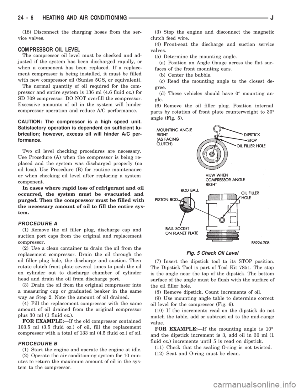
(6) Remove the oil filler plug. Position internal
parts by rotation of front plate counterweight to 30É
angle (Fig. 5).
(7) Insert the dipstick tool to its STOP position.
The Dipstick Tool is part of Tool Kit 7851. The stop
is the angle near the top of the dipstick. The bottom
surface of the angle must be flush with the surface of
the oil filler hole.
(8) Remove dipstick. Count increments of oil.
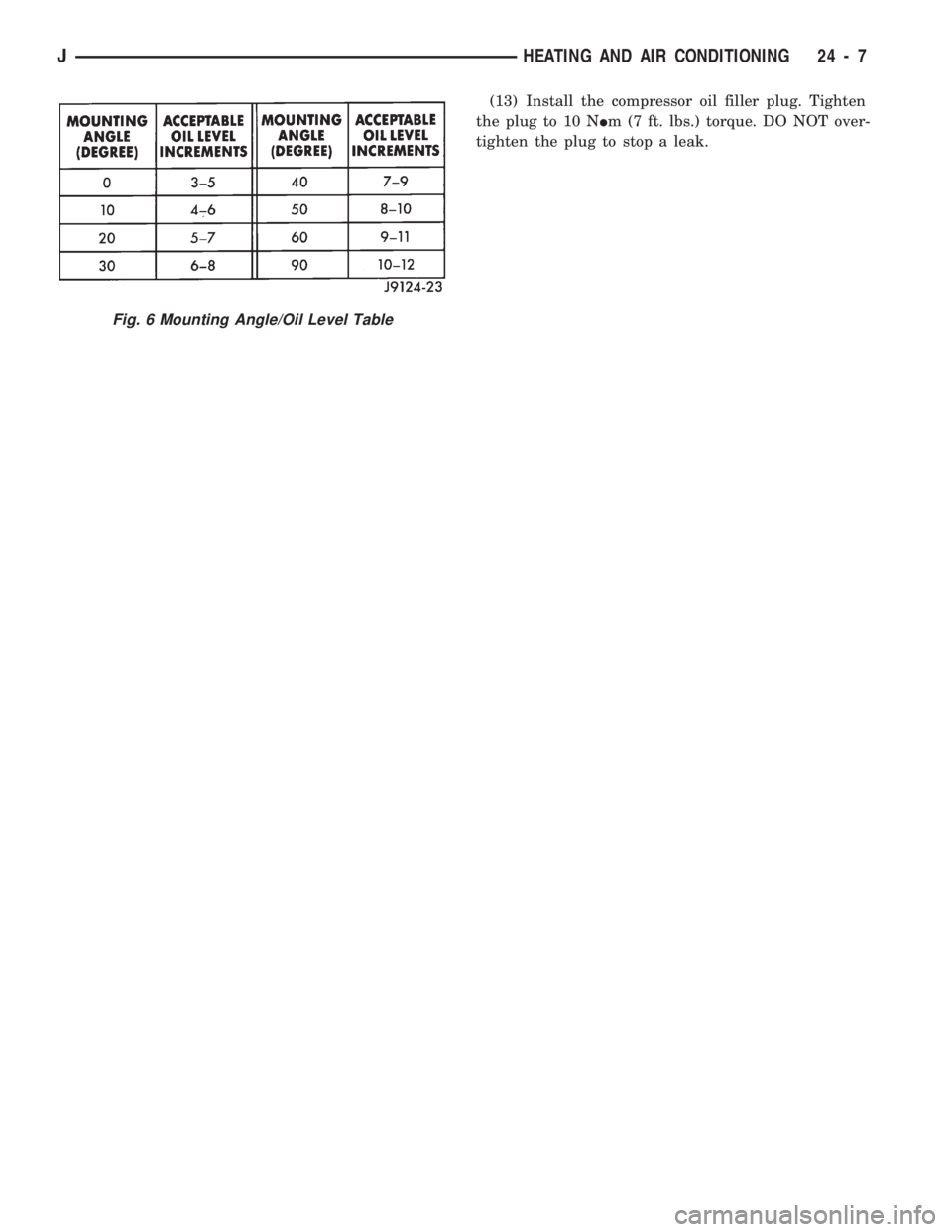
(9) Use mounting angle table to determine correct
oil level for the compressor (Fig. 6).
(10) If the increments read on the dipstick do not
match the table, add or subtract oil to the mid-range
value.
FOR EXAMPLE:ÐIf the mounting angle is 10É
and the dipstick increment is 3, add oil in 30 ml (1
fluid oz.) increments until 5 is read on dipstick.
(11) Check that the sealing O-ring is not twisted.
(12) Seat and O-ring must be clean.
Fig. 5 Check Oil Level
24 - 6 HEATING AND AIR CONDITIONINGJ
Page 1670 of 1784
(13) Install the compressor oil filler plug. Tighten
the plug to 10 NIm (7 ft. lbs.) torque. DO NOT over-
tighten the plug to stop a leak.
Fig. 6 Mounting Angle/Oil Level Table
JHEATING AND AIR CONDITIONING 24 - 7