JEEP CHEROKEE 1994 Service Repair Manual
Manufacturer: JEEP, Model Year: 1994, Model line: CHEROKEE, Model: JEEP CHEROKEE 1994Pages: 1784, PDF Size: 77.09 MB
Page 1681 of 1784
²Used belt tensionÐ623-712 N (140-160 lb-f).
(5) Remove the tape or plastic plugs from all the
suction and discharge openings and install the ser-
vice valves on the compressor.
(6) Connect the clutch lead wire.
(7) Connect negative cable to battery.
(8) Evacuate, charge and test the system for leaks.
MAGNETIC CLUTCH
The magnetic clutch consists of a stationary elec-
tro-magnetic coil and a rotating pulley and plate as-
sembly.
The electromagnetic coil is retained on the com-
pressor with a snap ring and is dimpled to maintain
its position.The pulley and plate assembly are mounted on the
compressor shaft.
When the compressor is not in operation, the pul-
ley free wheels on the clutch hub bearing. When the
coil is energized the plate is magnetically engaged
with the pulley and turns the compressor shaft.
REMOVAL
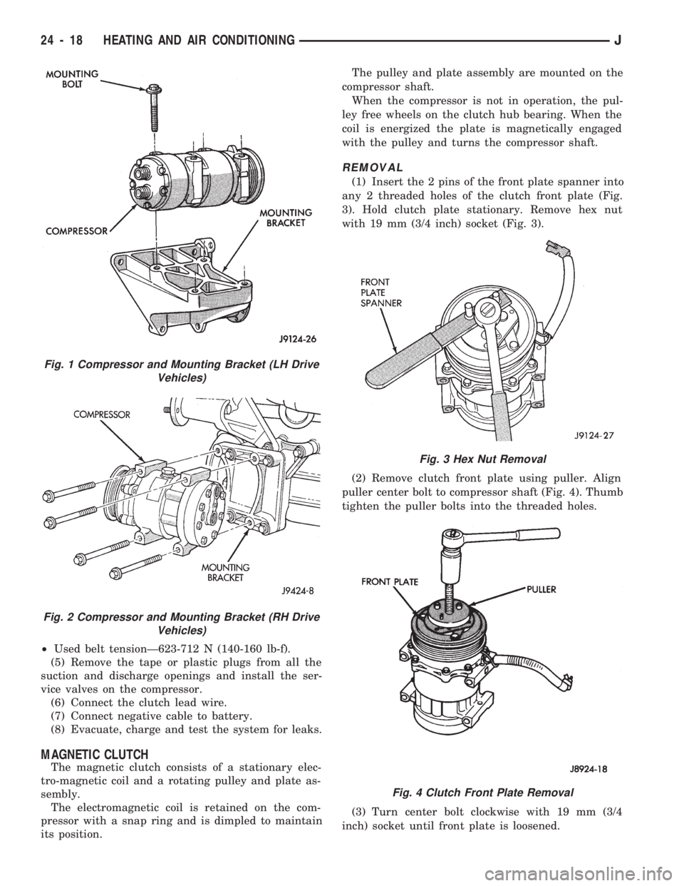
(1) Insert the 2 pins of the front plate spanner into
any 2 threaded holes of the clutch front plate (Fig.
3). Hold clutch plate stationary. Remove hex nut
with 19 mm (3/4 inch) socket (Fig. 3).
(2) Remove clutch front plate using puller. Align
puller center bolt to compressor shaft (Fig. 4). Thumb
tighten the puller bolts into the threaded holes.
(3) Turn center bolt clockwise with 19 mm (3/4
inch) socket until front plate is loosened.
Fig. 1 Compressor and Mounting Bracket (LH Drive
Vehicles)
Fig. 2 Compressor and Mounting Bracket (RH Drive
Vehicles)
Fig. 3 Hex Nut Removal
Fig. 4 Clutch Front Plate Removal
24 - 18 HEATING AND AIR CONDITIONINGJ
Page 1682 of 1784
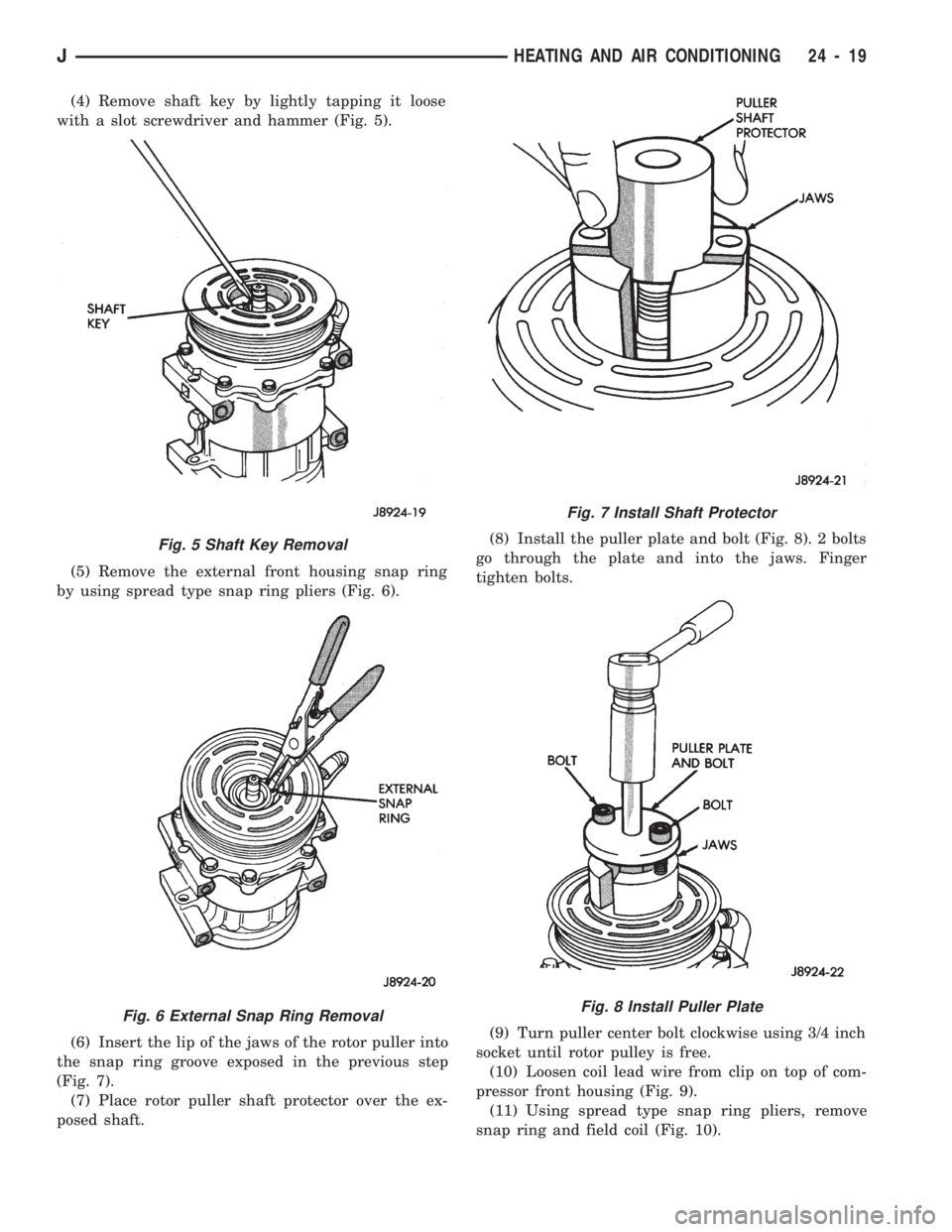
(4) Remove shaft key by lightly tapping it loose
with a slot screwdriver and hammer (Fig. 5).
(5) Remove the external front housing snap ring
by using spread type snap ring pliers (Fig. 6).
(6) Insert the lip of the jaws of the rotor puller into
the snap ring groove exposed in the previous step
(Fig. 7).
(7) Place rotor puller shaft protector over the ex-
posed shaft.(8) Install the puller plate and bolt (Fig. 8). 2 bolts
go through the plate and into the jaws. Finger
tighten bolts.
(9) Turn puller center bolt clockwise using 3/4 inch
socket until rotor pulley is free.
(10) Loosen coil lead wire from clip on top of com-
pressor front housing (Fig. 9).
(11) Using spread type snap ring pliers, remove
snap ring and field coil (Fig. 10).
Fig. 5 Shaft Key Removal
Fig. 6 External Snap Ring Removal
Fig. 7 Install Shaft Protector
Fig. 8 Install Puller Plate
JHEATING AND AIR CONDITIONING 24 - 19
Page 1683 of 1784
INSTALLATION
(1) Install the field coil with the snap ring.
(2) Place coil lead wire under clip on top of com-
pressor front housing and tighten the retaining
screw.
(3) Support the compressor on the 4 mounting ears
at the compressor rear. If a vise is being used, clamp
only on the mounting ears. Never clamp on the com-
pressor body.
(4) Align rotor assembly squarely on the front
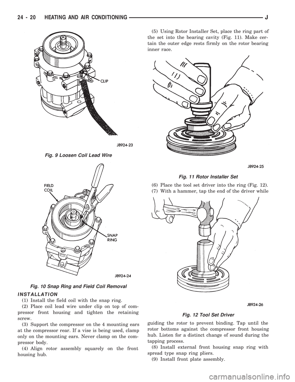
housing hub.(5) Using Rotor Installer Set, place the ring part of
the set into the bearing cavity (Fig. 11). Make cer-
tain the outer edge rests firmly on the rotor bearing
inner race.
(6) Place the tool set driver into the ring (Fig. 12).
(7) With a hammer, tap the end of the driver while
guiding the rotor to prevent binding. Tap until the
rotor bottoms against the compressor front housing
hub. Listen for a distinct change of sound during the
tapping process.
(8) Install external front housing snap ring with
spread type snap ring pliers.
(9) Install front plate assembly.
Fig. 9 Loosen Coil Lead Wire
Fig. 10 Snap Ring and Field Coil Removal
Fig. 11 Rotor Installer Set
Fig. 12 Tool Set Driver
24 - 20 HEATING AND AIR CONDITIONINGJ
Page 1684 of 1784
²Check that original clutch shims are in place on
compressor shaft.
²Replace compressor shaft key.
²Align front plate keyway to compressor shaft key.
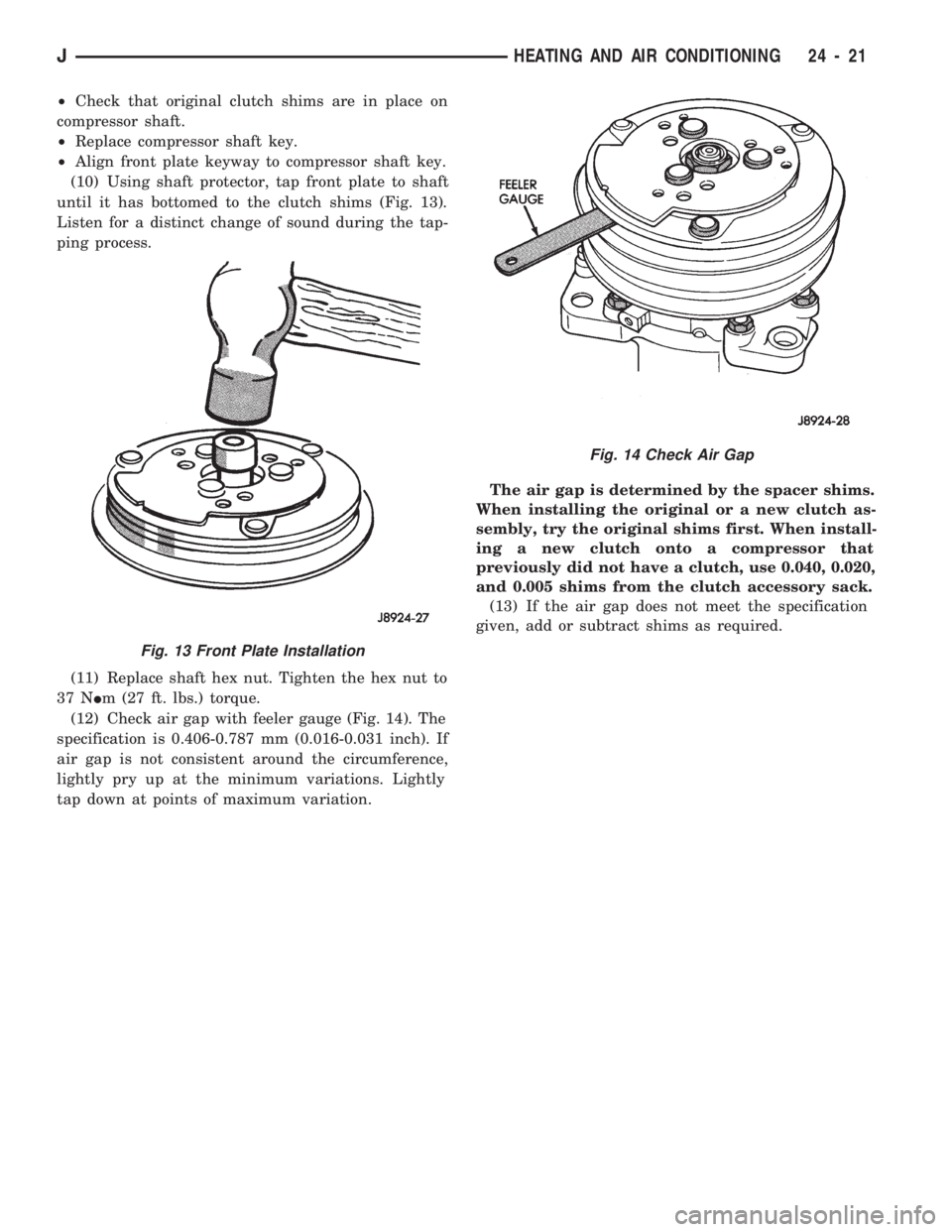
(10) Using shaft protector, tap front plate to shaft
until it has bottomed to the clutch shims (Fig. 13).
Listen for a distinct change of sound during the tap-
ping process.
(11) Replace shaft hex nut. Tighten the hex nut to
37 NIm (27 ft. lbs.) torque.
(12) Check air gap with feeler gauge (Fig. 14). The
specification is 0.406-0.787 mm (0.016-0.031 inch). If
air gap is not consistent around the circumference,
lightly pry up at the minimum variations. Lightly
tap down at points of maximum variation.The air gap is determined by the spacer shims.
When installing the original or a new clutch as-
sembly, try the original shims first. When install-
ing a new clutch onto a compressor that
previously did not have a clutch, use 0.040, 0.020,
and 0.005 shims from the clutch accessory sack.
(13) If the air gap does not meet the specification
given, add or subtract shims as required.
Fig. 13 Front Plate Installation
Fig. 14 Check Air Gap
JHEATING AND AIR CONDITIONING 24 - 21
Page 1685 of 1784
CLIMATE CONTROL SYSTEMÐXJ VEHICLES
INDEX
page page
A/C Recirculating Air Door Vacuum Motor
Replacement.......................... 31
Blower Motor Resistors Replacement......... 35
Blower Motor/Fan Replacement.............. 26
CondenserÐ4.0L Engines.................. 32
Condenser/Receiver DrierÐ2.5L Engines....... 31
Defroster Duct Replacement................ 29
Description............................. 22
Evaporator Coil.......................... 34
Evaporator/Blower Housing................. 33Expansion (H) Valve...................... 35
Heater and A/C Control Panel Replacement.... 26
Heater Control Cable Replacement........... 30
Heater Core............................ 28
Heater Core Housing Replacement........... 29
Heater/Defroster/Instrument Panel Outlet Door
Vacuum Motor Replacement............... 30
Receiver DrierÐ4.0L Engines............... 32
Temperature Control Thermostat............. 35
DESCRIPTION
The Climate Control System combines air condi-
tioning, heating and ventilating capabilities for vehi-
cles equipped with air conditioning. Vehicles without
air conditioning perform heating and ventilating
functions without the air conditioning evaporator.
Both systems consist basically of 2 parts:
²Blower and Air Inlet Assembly
²Heater Core and Air Distribution Assembly
These assemblies, initially installed as a single
unit, may be removed separately from under the in-
strument panel as required for service.
HEATER SYSTEM
The heater system is a blend air type. Outside air
is heated and then blended in varying amounts with
cooler outside air to obtain the desired discharge
temperature. A heater coolant valve provides full
flow to the heater core for all heating modes. The
heater coolant valve remains closed for the ventila-
tion mode, allowing discharge air to approach the
outside ambient air temperature.
AIR CONDITIONING SYSTEM
The air conditioning system has an evaporator to
cool and dehumidify the incoming outside air prior to
blending with the heated air. The evaporator is in
operation during the A/C mode and also in the de-
frost mode for defogging purposes. The evaporator is
not in operation at ambient temperatures below ap-
proximately -1ÉC (30ÉF). To maintain minimum evap-
orator temperature, a fixed thermostat setting switch
cycles the compressor clutch. The blower is operatingthe heater or air conditioning systems, except the
OFF mode. In this mode (OFF) the blower and the
outside air are shut off.
The cooling unit is mounted on the dash panel and
the cooled air is discharged from the instrument
panel registers. The registers are adjusted to provide
general or localized cooling.
SIGHT GLASS
The sight glass is located on top of the receiver/
drier. The sight glass provides a visual check of the
system refrigerant level. A continuous stream of bub-
bles will appear in the sight glass when the system
charge is low. Bubbles will not appear when the sys-
tem is fully charged.
LOW PRESSURE SWITCH
The low pressure switch disengages the magnetic
clutch if the pressure in the system drops below 193
kPa (28 psi). This will occur with a loss in refriger-
ant or with cold ambient temperature.
HEATER VALVE
The heater valve regulates coolant flow to the
heater core. It requires vacuum to shut off flow to
the heater core.
These vehicles are equipped with a bypass-type
heater water valve. When the heater valve is closed,
coolant flow to the heater core is bypassed back to
the engine. When the heater valve is open, coolant is
directed through the heater core and back to the en-
gine.
24 - 22 HEATING AND AIR CONDITIONINGJ
Page 1686 of 1784
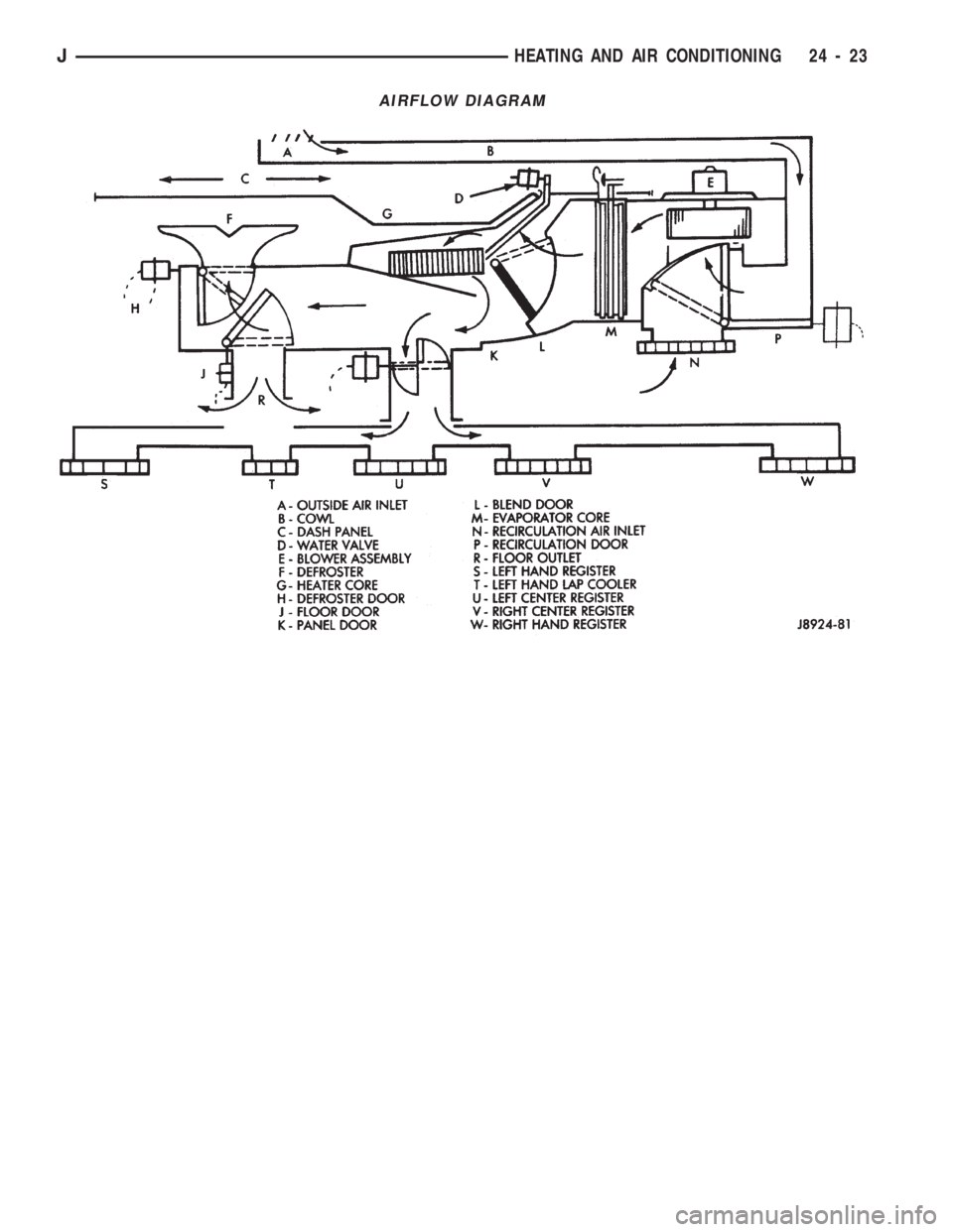
AIRFLOW DIAGRAM
JHEATING AND AIR CONDITIONING 24 - 23
Page 1687 of 1784
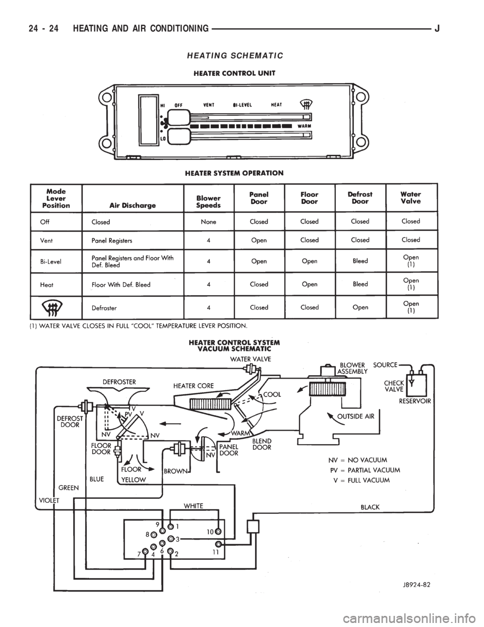
HEATING SCHEMATIC
24 - 24 HEATING AND AIR CONDITIONINGJ
Page 1688 of 1784
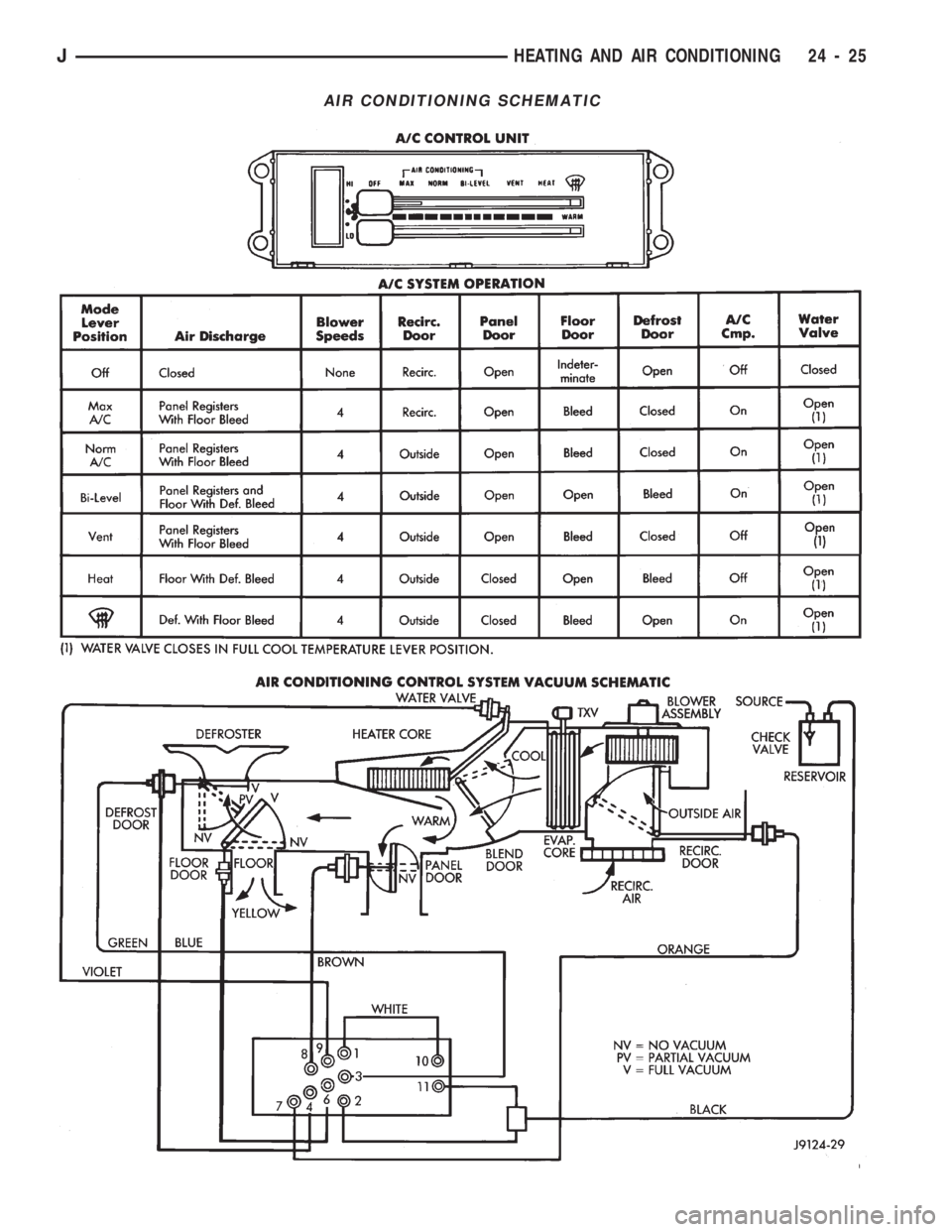
AIR CONDITIONING SCHEMATIC
JHEATING AND AIR CONDITIONING 24 - 25
Page 1689 of 1784
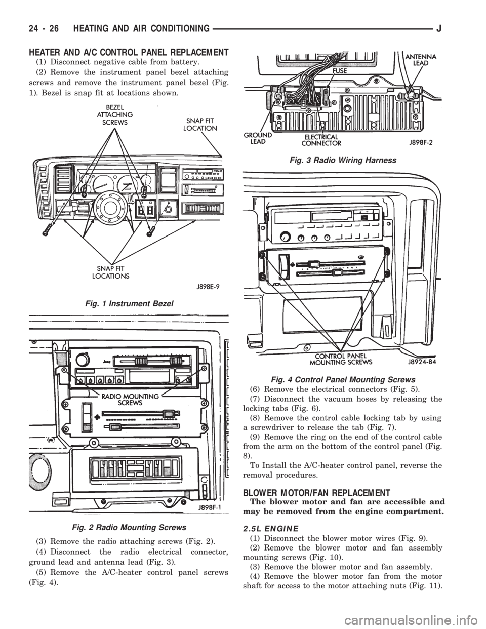
HEATER AND A/C CONTROL PANEL REPLACEMENT
(1) Disconnect negative cable from battery.
(2) Remove the instrument panel bezel attaching
screws and remove the instrument panel bezel (Fig.
1). Bezel is snap fit at locations shown.
(3) Remove the radio attaching screws (Fig. 2).
(4) Disconnect the radio electrical connector,
ground lead and antenna lead (Fig. 3).
(5) Remove the A/C-heater control panel screws
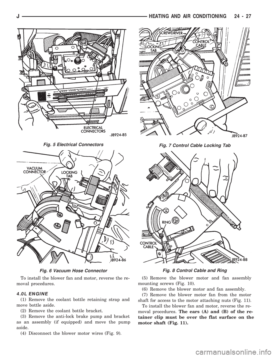
(Fig. 4).(6) Remove the electrical connectors (Fig. 5).
(7) Disconnect the vacuum hoses by releasing the
locking tabs (Fig. 6).
(8) Remove the control cable locking tab by using
a screwdriver to release the tab (Fig. 7).
(9) Remove the ring on the end of the control cable
from the arm on the bottom of the control panel (Fig.
8).
To Install the A/C-heater control panel, reverse the
removal procedures.
BLOWER MOTOR/FAN REPLACEMENT
The blower motor and fan are accessible and
may be removed from the engine compartment.
2.5L ENGINE
(1) Disconnect the blower motor wires (Fig. 9).
(2) Remove the blower motor and fan assembly
mounting screws (Fig. 10).
(3) Remove the blower motor and fan assembly.
(4) Remove the blower motor fan from the motor
shaft for access to the motor attaching nuts (Fig. 11).
Fig. 1 Instrument Bezel
Fig. 2 Radio Mounting Screws
Fig. 3 Radio Wiring Harness
Fig. 4 Control Panel Mounting Screws
24 - 26 HEATING AND AIR CONDITIONINGJ
Page 1690 of 1784
To install the blower fan and motor, reverse the re-
moval procedures.
4.0L ENGINE
(1) Remove the coolant bottle retaining strap and
move bottle aside.
(2) Remove the coolant bottle bracket.
(3) Remove the anti-lock brake pump and bracket
as an assembly (if equipped) and move the pump
aside.
(4) Disconnect the blower motor wires (Fig. 9).(5) Remove the blower motor and fan assembly
mounting screws (Fig. 10).
(6) Remove the blower motor and fan assembly.
(7) Remove the blower motor fan from the motor
shaft for access to the motor attaching nuts (Fig. 11).
To install the blower fan and motor, reverse the re-
moval procedures.The ears (A) and (B) of the re-
tainer clip must be over the flat surface on the
motor shaft (Fig. 11).
Fig. 5 Electrical Connectors
Fig. 6 Vacuum Hose Connector
Fig. 7 Control Cable Locking Tab
Fig. 8 Control Cable and Ring
JHEATING AND AIR CONDITIONING 24 - 27