JEEP CHEROKEE 1994 Service Repair Manual
Manufacturer: JEEP, Model Year: 1994, Model line: CHEROKEE, Model: JEEP CHEROKEE 1994Pages: 1784, PDF Size: 77.09 MB
Page 1701 of 1784
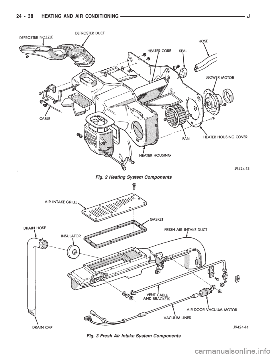
Fig. 3 Fresh Air Intake System Components
Fig. 2 Heating System Components
24 - 38 HEATING AND AIR CONDITIONINGJ
Page 1702 of 1784
FRESH AIR VENTILATION
The fresh air ventilating system (Fig. 3) is oper-
ated by the air control lever. When the lever is
moved to VENT position, outside air from the cowl
intake flows into the heater housing. Incoming air is
directed into the vehicle interior through vent doors
in the housing.
A door in the intake duct controls air flow into the
duct. The door is operated by a vacuum motor. The
motor is controlled by a vacuum switch in the heater
control panel. The vent air doors are opened and
closed by a cable and linkage operated by the air
control lever. Fresh air intake occurs only when the
lever is in the VENT position.
HEATER CONTROL PANEL REPLACEMENT
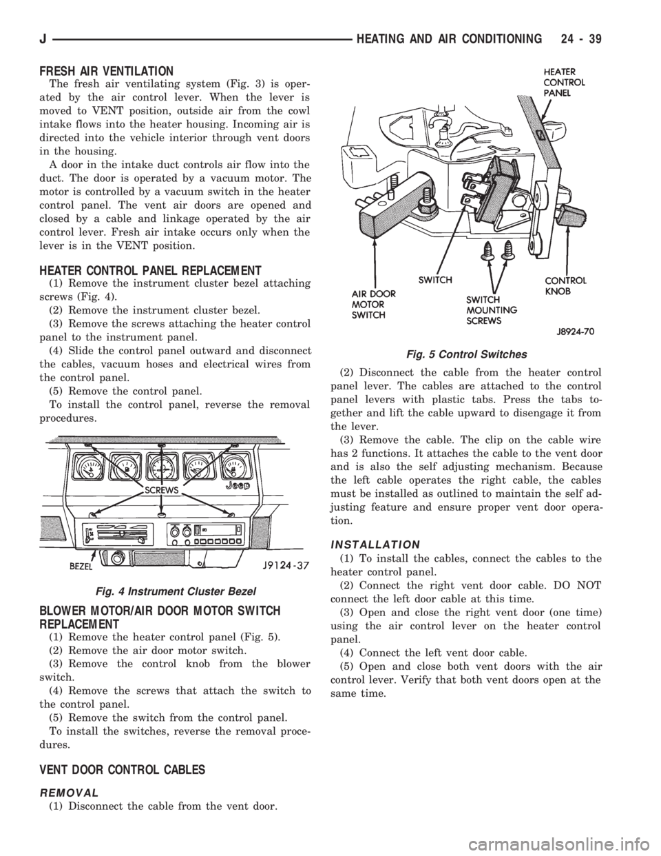
(1) Remove the instrument cluster bezel attaching
screws (Fig. 4).
(2) Remove the instrument cluster bezel.
(3) Remove the screws attaching the heater control
panel to the instrument panel.
(4) Slide the control panel outward and disconnect
the cables, vacuum hoses and electrical wires from
the control panel.
(5) Remove the control panel.
To install the control panel, reverse the removal
procedures.
BLOWER MOTOR/AIR DOOR MOTOR SWITCH
REPLACEMENT
(1) Remove the heater control panel (Fig. 5).
(2) Remove the air door motor switch.
(3) Remove the control knob from the blower
switch.
(4) Remove the screws that attach the switch to
the control panel.
(5) Remove the switch from the control panel.
To install the switches, reverse the removal proce-
dures.
VENT DOOR CONTROL CABLES
REMOVAL
(1) Disconnect the cable from the vent door.(2) Disconnect the cable from the heater control
panel lever. The cables are attached to the control
panel levers with plastic tabs. Press the tabs to-
gether and lift the cable upward to disengage it from
the lever.
(3) Remove the cable. The clip on the cable wire
has 2 functions. It attaches the cable to the vent door
and is also the self adjusting mechanism. Because
the left cable operates the right cable, the cables
must be installed as outlined to maintain the self ad-
justing feature and ensure proper vent door opera-
tion.
INSTALLATION
(1) To install the cables, connect the cables to the
heater control panel.
(2) Connect the right vent door cable. DO NOT
connect the left door cable at this time.
(3) Open and close the right vent door (one time)
using the air control lever on the heater control
panel.
(4) Connect the left vent door cable.
(5) Open and close both vent doors with the air
control lever. Verify that both vent doors open at the
same time.
Fig. 4 Instrument Cluster Bezel
Fig. 5 Control Switches
JHEATING AND AIR CONDITIONING 24 - 39
Page 1703 of 1784
HEATER CORE AND HOUSING
REMOVAL
WARNING: HOT ENGINE COOLANT CAN CAUSE
SEVERE BURNS. DO NOT OPEN THE RADIATOR
DRAIN COCK WHEN THE COOLING SYSTEM IS
HOT AND PRESSURIZED. ALLOW THE COOLANT
TO DECREASE TO ROOM TEMPERATURE BEFORE
STARTING REPAIR OPERATIONS.
(1) Drain approximately 1.9 liters (2 qts) of coolant
from the radiator. Drain the coolant into a clean con-
tainer.
(2) Disconnect the heater hoses.
(3) Disconnect the vent door cables.
(4) Disconnect the blower motor wire.
(5) Disconnect the defroster duct.
(6) Remove the nuts that attach the heater hous-
ing studs to the engine compartment side of the dash
panel.
(7) Remove the heater housing assembly by tilting
it downward, to disengage it from the defroster duct.
Pull it rearward and out from under the instrument
panel.
(8) Remove the heater hosing cover from the hous-
ing.
(9) Remove the heater core from the housing.
INSTALLATION
(1) Install the heater core in the housing and in-
stall the cover on the housing.
(2) Position the heater housing on the dash panel.
Be sure the housing studs all extend through the
dash panel.
(3) Install the seals on the heater core outlet and
inlet tubes and over the blower motor housing.
(4) Install the attaching nuts on the housing studs.
CAUTION: DO NOT over tighten the attaching nuts.
The housing could become distorted causing air
leaks and improper heater door operation. Tighten
the nuts alternately and evenly until 2 stud threads
are visible beyond each nut.
(5) Connect the defroster duct to the housing.
(6) Connect the blower motor wire.
(7) Connect the vent door control cables.
(8) Connect the heater hoses.
(9) Fill and bleed the cooling system.
(10) Check system operation.
BLOWER MOTOR (HEATING)
REMOVAL
(1) Remove the heater housing.
(2) Remove the blower motor-to-heater housing at-
taching screws/nuts.
(3) Remove the blower motor from the housing.
INSTALLATION
(1) Position the blower motor into the housing.
(2) Install and tighten the blower motor-to-heater
housing attaching screws/nuts.
(3) Install the heater housing.
(4) Check blower motor and heater operation.
DEFROSTER NOZZLE AND DUCT
REMOVAL
WARNING: HOT ENGINE COOLANT CAN CAUSE
SEVERE BURNS. DO NOT OPEN THE RADIATOR
DRAIN COCK WHEN THE COOLING SYSTEM IS
HOT AND PRESSURIZED. ALLOW THE COOLANT
TO DECREASE TO ROOM TEMPERATURE BEFORE
STARTING REPAIR OPERATIONS.
(1) Drain approximately 1.9 liters (2 qts) of coolant
from the radiator. Drain the coolant into a clean con-
tainer.
(2) Disconnect the heater hoses.
(3) Remove the nuts attaching the heater housing
studs to the engine compartment side of the dash
panel.
(4) Disconnect the speedometer cable.
(5) Remove the glove box.
(6) Tilt the heater housing back and pull it rear-
ward and out from under the instrument panel.
(7) Disconnect the vent control cables.
(8) Remove the fresh air intake grille from the
cowl.
(9) Remove the fresh air intake duct.
(10) Lower the windshield.
(11) Remove the defroster nozzle attaching screws
and remove the nozzle and duct.
INSTALLATION
(1) Install the defroster nozzle and duct.
(2) Raise and secure the windshield.
(3) Install the fresh air intake duct.
(4) Install the fresh air intake grille on the cowl.
(5) Install the vent cables.
(6) Position the heater housing on the dash panel.
Be sure all the housing studs extend through the
dash panel.
(7) Install the seals on the blower motor and the
heater core inlet and outlet tubes.
(8) Install the attaching nuts on the housing studs.
CAUTION: DO NOT over tighten the attaching nuts.
The housing could become distorted causing air
leaks and improper heater door operation. Tighten
the nuts alternately and evenly until 2 stud threads
are visible beyond each nut.
(9) Install the glove box.
(10) Connect the speedometer cable.
(11) Connect the heater hoses.
24 - 40 HEATING AND AIR CONDITIONINGJ
Page 1704 of 1784
(12) Fill and bleed the cooling system.
FRESH AIR DOOR VACUUM MOTOR
REMOVAL
(1) Remove the glove box and assist handle.
(2) Disconnect the vacuum hose from the motor.
(3) Remove the motor lever retaining clip.
(4) Remove the motor attaching nuts and remove
the motor from the fresh air duct.
INSTALLATION
(1) Position the motor on the fresh air duct and in-
stall the motor attaching nuts.
(2) Align the motor lever with the air door lever
and install the lever retaining clip.
(3) Connect the vacuum hose to the motor.
(4) Install the glove box and assist handle.
FRESH AIR INTAKE DUCT
REMOVAL
WARNING: HOT ENGINE COOLANT CAN CAUSE
SEVERE BURNS. DO NOT OPEN THE RADIATOR
DRAIN COCK WHEN THE COOLING SYSTEM IS
HOT AND PRESSURIZED. ALLOW THE COOLANT
TO DECREASE TO ROOM TEMPERATURE BEFORE
STARTING REPAIR OPERATIONS.
(1) Drain approximately 1.9 liters (2 qts) of coolant
from the radiator. Drain the coolant into a clean con-
tainer.
(2) Disconnect the heater hoses.
(3) Remove the nuts attaching the heater housing
studs to the dash panel from inside the engine com-
partment.
(4) Disconnect the speedometer cable.
(5) Remove the glove box and assist handle.
(6) Tilt the heater housing back and pull it rear-
ward and out from under the instrument panel.
(7) Disconnect the vent cables.
(8) Remove the fresh air intake grille from the
cowl.
(9) Remove the fresh air intake duct.
INSTALLATION
(1) Install the fresh air intake duct.
(2) Install the defroster nozzle and duct.
(3) Raise and secure the windshield.
(4) Install the fresh air grille on the cowl.
(5) Install the vent cables.
(6) Position the heater housing on the dash panel.
Be sure all the housing studs extend through the
dash panel.
(7) Install the seals on the blower motor and
heater core inlet and outlet tubes.
(8) Install the attaching nuts on the heater hous-
ing studs.CAUTION: DO NOT over tighten the attaching nuts.
The housing could become distorted causing air
leaks and improper heater door operation. Tighten
the nuts alternately and evenly until 2 stud threads
are visible beyond each nut.
(9) Install the glove box and assist handle.
(10) Connect the speedometer cable.
(11) Connect the heater hoses.
(12) Fill and bleed the cooling system.
DESCRIPTION (AIR CONDITIONING)
The evaporator, blower fan and motor, thermostat,
expansion valve, capillary tube, air outlets and sys-
tem controls are located in the evaporator housing.
The evaporator housing is mounted under the instru-
ment panel. The compressor, condenser, receiver-
dryer and refrigerant lines are located in the engine
compartment.
A rotary-type compressor with magnetic clutch op-
erated drive pulley is used for all vehicles equipped
with air conditioning.
SIGHT GLASS
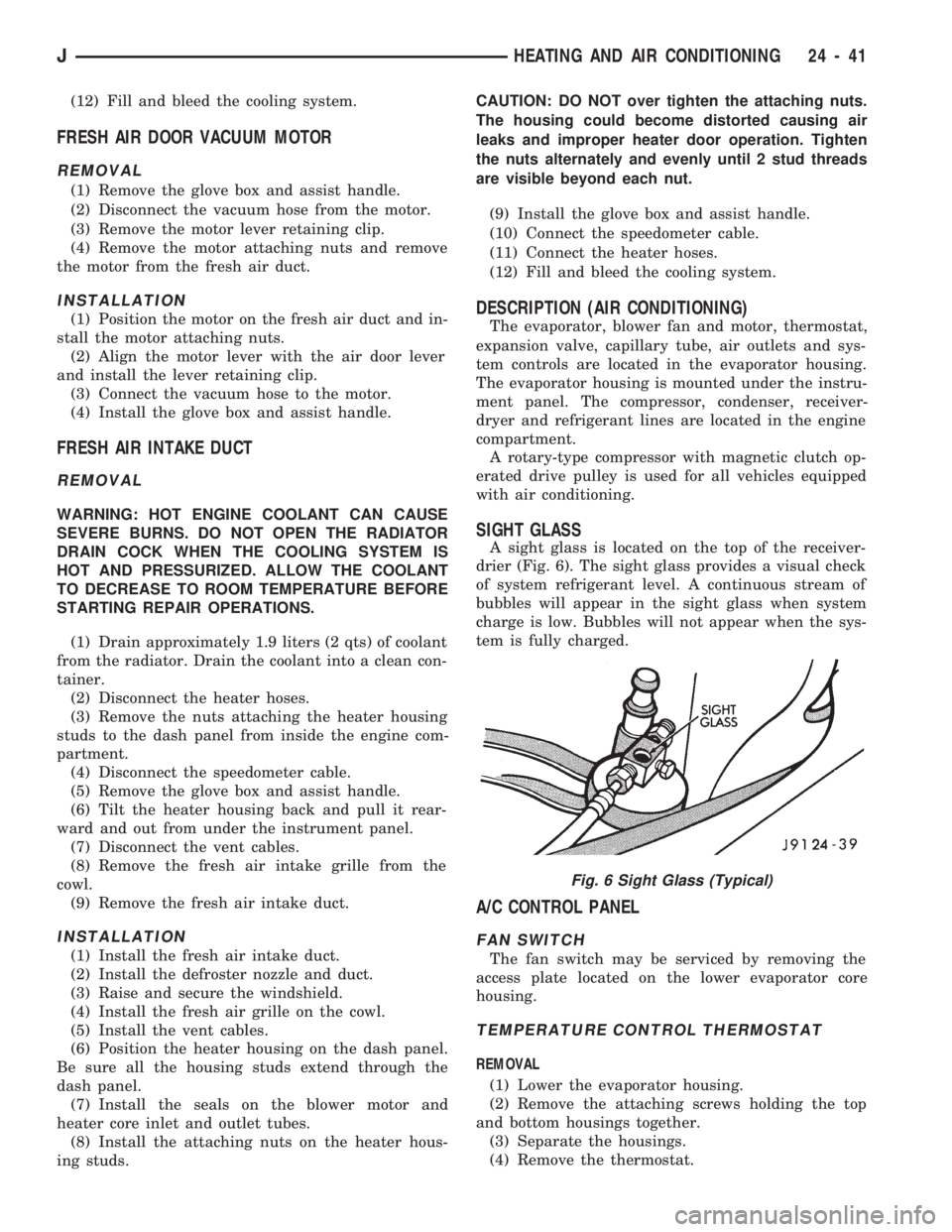
A sight glass is located on the top of the receiver-
drier (Fig. 6). The sight glass provides a visual check
of system refrigerant level. A continuous stream of
bubbles will appear in the sight glass when system
charge is low. Bubbles will not appear when the sys-
tem is fully charged.
A/C CONTROL PANEL
FAN SWITCH
The fan switch may be serviced by removing the
access plate located on the lower evaporator core
housing.
TEMPERATURE CONTROL THERMOSTAT
REMOVAL
(1) Lower the evaporator housing.
(2) Remove the attaching screws holding the top
and bottom housings together.
(3) Separate the housings.
(4) Remove the thermostat.
Fig. 6 Sight Glass (Typical)
JHEATING AND AIR CONDITIONING 24 - 41
Page 1705 of 1784
INSTALLATION
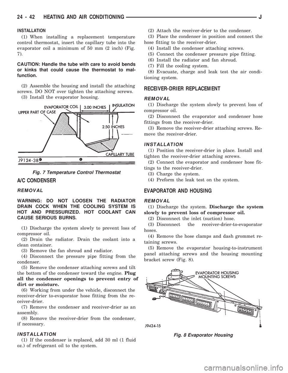
(1) When installing a replacement temperature
control thermostat, insert the capillary tube into the
evaporator coil a minimum of 50 mm (2 inch) (Fig.
7).
CAUTION: Handle the tube with care to avoid bends
or kinks that could cause the thermostat to mal-
function.
(2) Assemble the housing and install the attaching
screws. DO NOT over tighten the attaching screws.
(3) Install the evaporator housing.
A/C CONDENSER
REMOVAL
WARNING: DO NOT LOOSEN THE RADIATOR
DRAIN COCK WHEN THE COOLING SYSTEM IS
HOT AND PRESSURIZED. HOT COOLANT CAN
CAUSE SERIOUS BURNS.
(1) Discharge the system slowly to prevent loss of
compressor oil.
(2) Drain the radiator. Drain the coolant into a
clean container.
(3) Remove the fan shroud and radiator.
(4) Disconnect the pressure pipe fitting from the
condenser.
(5) Remove the condenser attaching screws and tilt
the bottom of the condenser toward the engine.Plug
all the condenser openings to prevent entry of
dirt or moisture.
(6) Working from under the vehicle, disconnect the
receiver-drier to-evaporator hose fitting from the re-
ceiver-drier.
(7) Remove the condenser and receiver-drier as an
assembly.
(8) Remove the receiver-drier from the condenser,
if necessary.
INSTALLATION
(1) If the condenser is replaced, add 30 ml (1 fluid
oz.) of refrigerant oil to the system.(2) Attach the receiver-drier to the condenser.
(3) Place the condenser in position and connect the
hose fitting to the receiver-drier.
(4) Install the condenser attaching screws.
(5) Connect the condenser pressure pipe fitting.
(6) Install the radiator and fan shroud.
(7) Fill the cooling system.
(8) Evacuate, charge and leak test the air condi-
tioning system.
RECEIVER-DRIER REPLACEMENT
REMOVAL
(1) Discharge the system slowly to prevent loss of
compressor oil.
(2) Disconnect the evaporator and condenser hose
fittings from the receiver-drier.
(3) Remove the receiver-drier attaching screws. Re-
move the receiver-drier.
INSTALLATION
(1) Position the receiver-drier in place. Install and
tighten the receiver-drier attaching screws.
(2) Connect the evaporator and condenser hose fit-
tings to the receiver-drier.
(3) Charge the system.
(4) Preform the leak test on the system.
EVAPORATOR AND HOUSING
REMOVAL
(1) Discharge the system.Discharge the system
slowly to prevent loss of compressor oil.
(2) Disconnect the inlet (suction) hose.
(3) Disconnect the receiver-drier-to-evaporator
hoses.
(4) Remove the hose clamps and dash grommet re-
taining screws.
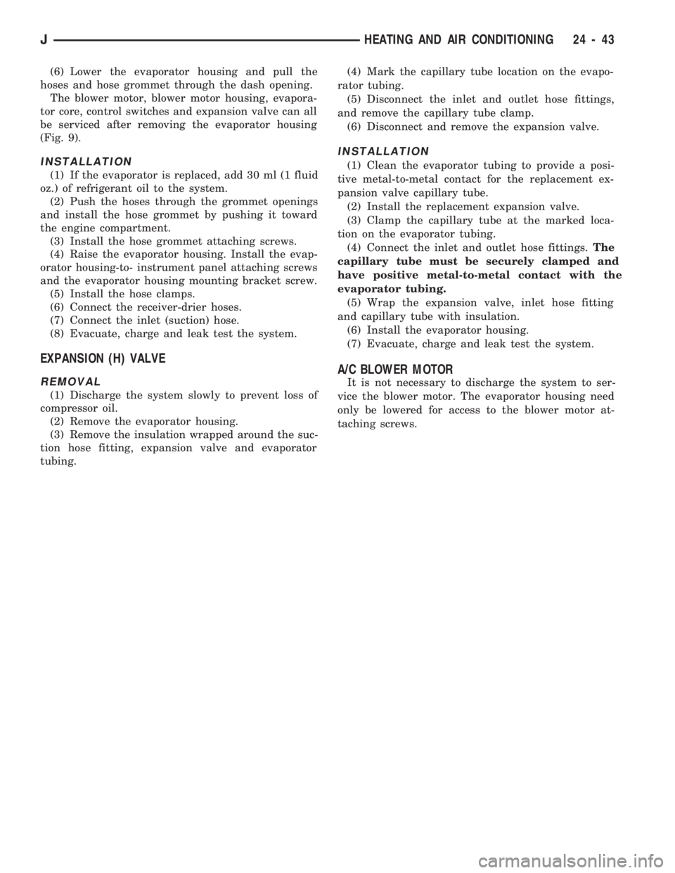
(5) Remove the evaporator housing-to-instrument
panel attaching screws and the housing mounting
bracket screw (Fig. 8).
Fig. 7 Temperature Control Thermostat
Fig. 8 Evaporator Housing
24 - 42 HEATING AND AIR CONDITIONINGJ
Page 1706 of 1784
(6) Lower the evaporator housing and pull the
hoses and hose grommet through the dash opening.
The blower motor, blower motor housing, evapora-
tor core, control switches and expansion valve can all
be serviced after removing the evaporator housing
(Fig. 9).
INSTALLATION
(1) If the evaporator is replaced, add 30 ml (1 fluid
oz.) of refrigerant oil to the system.
(2) Push the hoses through the grommet openings
and install the hose grommet by pushing it toward
the engine compartment.
(3) Install the hose grommet attaching screws.
(4) Raise the evaporator housing. Install the evap-
orator housing-to- instrument panel attaching screws
and the evaporator housing mounting bracket screw.
(5) Install the hose clamps.
(6) Connect the receiver-drier hoses.
(7) Connect the inlet (suction) hose.
(8) Evacuate, charge and leak test the system.
EXPANSION (H) VALVE
REMOVAL
(1) Discharge the system slowly to prevent loss of
compressor oil.
(2) Remove the evaporator housing.
(3) Remove the insulation wrapped around the suc-
tion hose fitting, expansion valve and evaporator
tubing.(4) Mark the capillary tube location on the evapo-
rator tubing.
(5) Disconnect the inlet and outlet hose fittings,
and remove the capillary tube clamp.
(6) Disconnect and remove the expansion valve.
INSTALLATION
(1) Clean the evaporator tubing to provide a posi-
tive metal-to-metal contact for the replacement ex-
pansion valve capillary tube.
(2) Install the replacement expansion valve.
(3) Clamp the capillary tube at the marked loca-
tion on the evaporator tubing.
(4) Connect the inlet and outlet hose fittings.The
capillary tube must be securely clamped and
have positive metal-to-metal contact with the
evaporator tubing.
(5) Wrap the expansion valve, inlet hose fitting
and capillary tube with insulation.
(6) Install the evaporator housing.
(7) Evacuate, charge and leak test the system.
A/C BLOWER MOTOR
It is not necessary to discharge the system to ser-
vice the blower motor. The evaporator housing need
only be lowered for access to the blower motor at-
taching screws.
JHEATING AND AIR CONDITIONING 24 - 43
Page 1707 of 1784
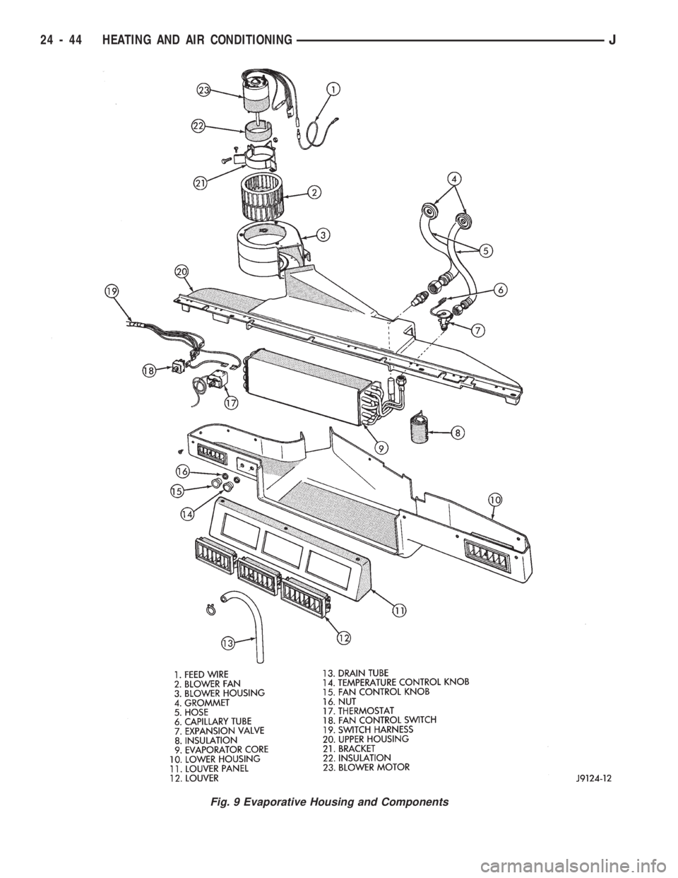
Fig. 9 Evaporative Housing and Components
24 - 44 HEATING AND AIR CONDITIONINGJ
Page 1708 of 1784
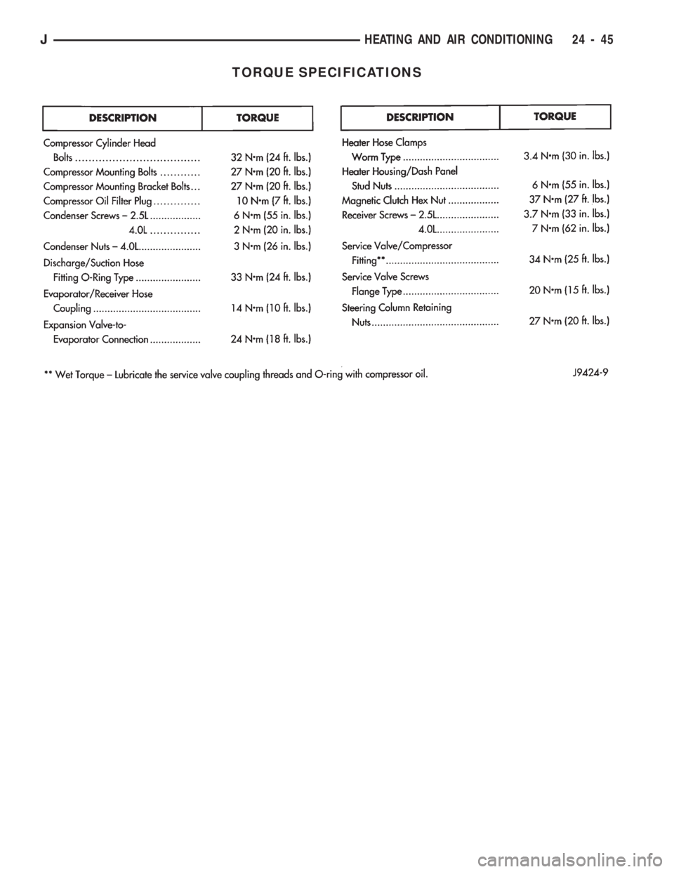
TORQUE SPECIFICATIONS
JHEATING AND AIR CONDITIONING 24 - 45
Page 1709 of 1784

Page 1710 of 1784
AIR CONDITIONING
CONTENTS
page page
AIR CONDITIONING EQUIPMENT........... 4
AIR CONDITIONING PERFORMANCE TESTS . . 5
GENERAL INFORMATION.................. 1
REFRIGERANT LEAK TESTING, DISCHARGING,
EVACUATING AND CHARGING............ 8REFRIGERANT OIL....................... 9
SERVICE PRECAUTIONS.................. 3
WARNINGS AND CAUTIONS FOR R134A
SYSTEM.............................. 3
GENERAL INFORMATION
A/C COMPONENTS
COMPRESSORÐThe SD-709 Compressor is used
on all models. The compressor compresses the low-
pressure refrigerant vapor from the evaporator into a
high pressure, high temperature vapor. The compres-
sor is serviced as an assembly only.
CLUTCH PULLEY AND COILÐThey are
mounted on the compressor and providing a way to
drive the compressor. The compressor clutch and coil
are the only serviced parts on the SD-709 compres-
sor. When the compressor is not in operation, the
pulley free wheels on the clutch hub bearing. When
the coil is energized the clutch plate is magnetically
engaged with the pulley and turns the compressor
shaft.
CONDENSERÐThe condenser is located in front
of the engine radiator. Its function is to cool the hot
high pressure refrigerant gas. This causes it to con-
dense into high pressure liquid refrigerant.
FILTER-DRIERÐThe drier is used to remove con-
taminates and traces of moisture from the refriger-
ant system.
SIGHT-GLASSÐThe sight glass is located on top
of the filter drier. It is used as a diagnostic tool to ob-
serve refrigerant flow.
LOW-PRESSURE HIGH-PRESSURE CUT-OFF
SWITCHÐThe switch is located on the filter drier
and is wired in series with compressor clutch. When
the pressure drops down to 193 kPa (28 psi) the
switch interrupts the power to the compressor clutch.
When the pressure increases above 3100 to 3375 kPa
(450 to 490 psi) the switch interrupts the power to
the compressor clutch.
HIGH PRESSURE RELIEF VALVEÐThe valve
is located on the filter drier. The valve is used to pre-
vent excessive pressure up build of 3445 to 4135
kPag (500 to 600 psi) and above. This will prevent
damage to the compressor and other system compo-
nents.EXPANSION VALVEÐThe expansion valve is lo-
cated in the engine compartment on XJ vehicles. On
YJ vehicles it is located behind the A/C housing. Its
function is to meter refrigerant into the evaporator in
accordance with cooling requirements.
EVAPORATOR COILÐThe coil is located in the
A/C housing. Its function is to remove heat and de-
humidify the air before it enters the vehicle.
FIN SENSING CYCLING CLUTCH SWITCHÐ
The switch is attached to the evaporator coil. This
switch prevents condensate water on the evaporator
coil from freezing. It does this by cycling the com-
pressor clutch on and off. This switch is used onXJ
only
THERMOSTATÐThe thermostat is located in the
evaporator housing. Its function is to cycle the com-
pressor clutch to control temperature. The thermo-
stat is used on theYJonly.
REFRIGERANT LINESÐThe lines are used to
carry the refrigerant between the various system
components.
SERVICE PORTSÐThe high pressure service
port is located on the discharge line near the com-
pressor. The low pressure service port is located on
the suction line near the compressor. The compressor
no longer uses service valves.
After servicing the refrigerant system, always in-
stall service port caps.
REFRIGERANT
The vehicles use a new type of refrigerant called
R-134a. It is a non-toxic, non-flammable, clear color-
less liquified gas.
R-134a refrigerant is not compatible with R-12 re-
frigerant in an air conditioning system. A small
amount of R-12 in a R-134a system will cause com-
pressor failure, refrigerant oil sludge or poor A/C per-
formance.
JAIR CONDITIONING1