JEEP CHEROKEE 1995 Service Repair Manual
Manufacturer: JEEP, Model Year: 1995, Model line: CHEROKEE, Model: JEEP CHEROKEE 1995Pages: 2198, PDF Size: 82.83 MB
Page 1271 of 2198
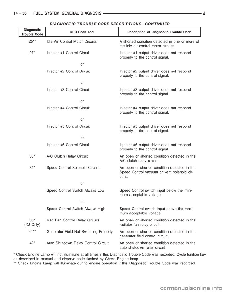
DIAGNOSTIC TROUBLE CODE DESCRIPTIONSÐCONTINUED
Diagnostic
Trouble CodeDRB Scan Tool Description of Diagnostic Trouble Code
25** Idle Air Control Motor Circuits A shorted condition detected in one or more of
the idle air control motor circuits.
27* Injector #1 Control Circuit Injector #1 output driver does not respond
properly to the control signal.
or
Injector #2 Control Circuit Injector #2 output driver does not respond
properly to the control signal.
or
Injector #3 Control Circuit Injector #3 output driver does not respond
properly to the control signal.
or
Injector #4 Control Circuit Injector #4 output driver does not respond
properly to the control signal.
or
Injector #5 Control Circuit Injector #5 output driver does not respond
properly to the control signal.
or
Injector #6 Control Circuit Injector #6 output driver does not respond
properly to the control signal.
33* A/C Clutch Relay Circuit An open or shorted condition detected in the
A/C clutch relay circuit.
34* Speed Control Solenoid Circuits An open or shorted condition detected in the
Speed Control vacuum or vent solenoid cir-
cuits.
or
Speed Control Switch Always Low Speed Control switch input below the mini-
mum acceptable voltage.
or
Speed Control Switch Always High Speed Control switch input above the maxi-
mum acceptable voltage.
35*
(XJ Only)Rad Fan Control Relay Circuits An open or shorted condition detected in the
radiator fan relay circuit.
41** Generator Field Not Switching Properly An open or shorted condition detected in the
generator field control circuit.
42* Auto Shutdown Relay Control Circuit An open or shorted condition detected in the
auto shutdown relay circuit.
* Check Engine Lamp will not illuminate at all times if this Diagnostic Trouble Code was recorded. Cycle Ignition key
as described in manual and observe code flashed by Check Engine lamp.
** Check Engine Lamp will illuminate during engine operation if this Diagnostic Trouble Code was recorded.
14 - 56 FUEL SYSTEM GENERAL DIAGNOSISJ
Page 1272 of 2198
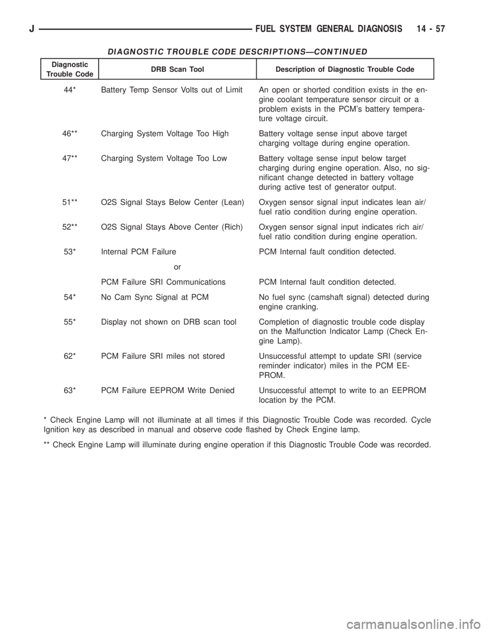
DIAGNOSTIC TROUBLE CODE DESCRIPTIONSÐCONTINUED
Diagnostic
Trouble CodeDRB Scan Tool Description of Diagnostic Trouble Code
44* Battery Temp Sensor Volts out of Limit An open or shorted condition exists in the en-
gine coolant temperature sensor circuit or a
problem exists in the PCM's battery tempera-
ture voltage circuit.
46** Charging System Voltage Too High Battery voltage sense input above target
charging voltage during engine operation.
47** Charging System Voltage Too Low Battery voltage sense input below target
charging during engine operation. Also, no sig-
nificant change detected in battery voltage
during active test of generator output.
51** O2S Signal Stays Below Center (Lean) Oxygen sensor signal input indicates lean air/
fuel ratio condition during engine operation.
52** O2S Signal Stays Above Center (Rich) Oxygen sensor signal input indicates rich air/
fuel ratio condition during engine operation.
53* Internal PCM Failure PCM Internal fault condition detected.
or
PCM Failure SRI Communications PCM Internal fault condition detected.
54* No Cam Sync Signal at PCM No fuel sync (camshaft signal) detected during
engine cranking.
55* Display not shown on DRB scan tool Completion of diagnostic trouble code display
on the Malfunction Indicator Lamp (Check En-
gine Lamp).
62* PCM Failure SRI miles not stored Unsuccessful attempt to update SRI (service
reminder indicator) miles in the PCM EE-
PROM.
63* PCM Failure EEPROM Write Denied Unsuccessful attempt to write to an EEPROM
location by the PCM.
* Check Engine Lamp will not illuminate at all times if this Diagnostic Trouble Code was recorded. Cycle
Ignition key as described in manual and observe code flashed by Check Engine lamp.
** Check Engine Lamp will illuminate during engine operation if this Diagnostic Trouble Code was recorded.
JFUEL SYSTEM GENERAL DIAGNOSIS 14 - 57
Page 1273 of 2198
MULTI-PORT FUEL INJECTION (MFI)ÐCOMPONENT REMOVAL/INSTALLATION
INDEX
page page
Accelerator Pedal and Throttle Cable........... 58
Air Cleaner Element....................... 59
Air Cleaner Housing....................... 58
Air Conditioning (A/C) Clutch Relay............ 58
Automatic Shutdown (ASD) Relay............. 59
Brake Switch............................ 59
Camshaft Position Sensor................... 60
Crankshaft Position Sensor.................. 60
Engine Coolant Temperature Sensor........... 60
Fuel Filter............................... 60
Fuel Injector............................. 60
Fuel Pressure Regulator.................... 61
Fuel Pump Module........................ 61
Fuel Pump Relay......................... 61
Fuel Rail Assembly........................ 62
Fuel System Pressure Release Procedure....... 62
Fuel Tank Pressure Relief/Rollover Valve........ 62Fuel Tanks.............................. 62
Fuel Tubes/Lines/Hoses and Clamps........... 62
Idle Air Control (IAC) Motor.................. 62
Ignition Coil............................. 62
Intake Manifold........................... 63
Intake Manifold Air Temperature Sensor......... 60
Manifold Absolute Pressure (Map) Sensor....... 63
Oxygen (O2S) Sensor...................... 63
Park Neutral Switch....................... 63
Power Steering Pressure SwitchÐ2.5L
Engine Only............................ 63
Powertrain Control Module (PCM)............. 64
Quick-Connect Fittings..................... 64
Throttle Body............................ 64
Throttle Position Sensor (TPS)............... 65
Torque Converter Clutch Relay............... 65
Vehicle Speed Sensor...................... 66
ACCELERATOR PEDAL AND THROTTLE CABLE
Refer to the Accelerator Pedal and Throttle Cable
section of this group for removal/installation proce-
dures.
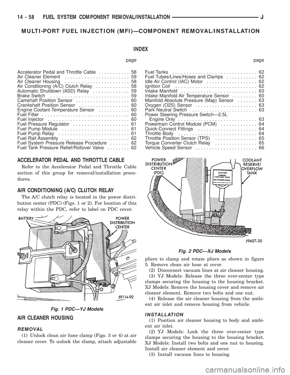
AIR CONDITIONING (A/C) CLUTCH RELAY
The A/C clutch relay is located in the power distri-
bution center (PDC) (Figs. 1 or 2). For location of this
relay within the PDC, refer to label on PDC cover.
AIR CLEANER HOUSING
REMOVAL
(1) Unlock clean air hose clamp (Figs. 3 or 4) at air
cleaner cover. To unlock the clamp, attach adjustablepliers to clamp and rotate pliers as shown in figure
5. Remove clean air hose at cover.
(2) Disconnect vacuum lines at air cleaner housing.
(3) YJ Models: Release the three over-center type
clamps securing the housing to the housing bracket.
XJ Models: Remove the housing cover and remove air
cleaner element. Remove two bolts and one nut.
(4) Release the air cleaner housing from the ambi-
ent air inlet and remove housing from vehicle.
INSTALLATION
(1) Position air cleaner housing to body and ambi-
ent air inlet.
(2) YJ Models: Lock the three over-center type
clamps securing the housing to the housing bracket.
XJ Models: Install two bolts and one nut to housing.
Install air cleaner element and cover.
(3) Install vacuum lines to housing.
Fig. 1 PDCÐYJ Models
Fig. 2 PDCÐXJ Models
14 - 58 FUEL SYSTEM COMPONENT REMOVAL/INSTALLATIONJ
Page 1274 of 2198
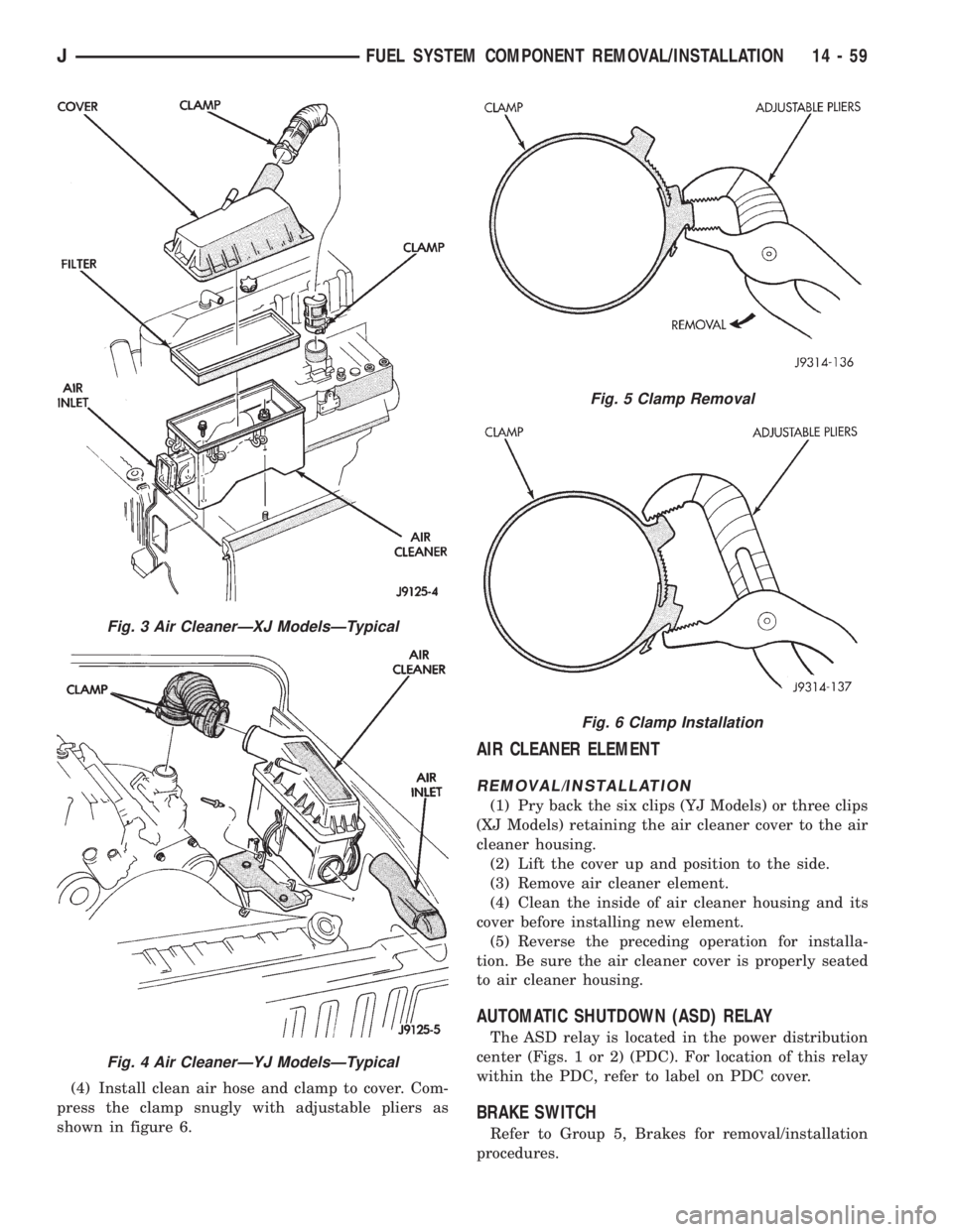
(4) Install clean air hose and clamp to cover. Com-
press the clamp snugly with adjustable pliers as
shown in figure 6.
AIR CLEANER ELEMENT
REMOVAL/INSTALLATION
(1) Pry back the six clips (YJ Models) or three clips
(XJ Models) retaining the air cleaner cover to the air
cleaner housing.
(2) Lift the cover up and position to the side.
(3) Remove air cleaner element.
(4) Clean the inside of air cleaner housing and its
cover before installing new element.
(5) Reverse the preceding operation for installa-
tion. Be sure the air cleaner cover is properly seated
to air cleaner housing.
AUTOMATIC SHUTDOWN (ASD) RELAY
The ASD relay is located in the power distribution
center (Figs. 1 or 2) (PDC). For location of this relay
within the PDC, refer to label on PDC cover.
BRAKE SWITCH
Refer to Group 5, Brakes for removal/installation
procedures.
Fig. 3 Air CleanerÐXJ ModelsÐTypical
Fig. 4 Air CleanerÐYJ ModelsÐTypical
Fig. 5 Clamp Removal
Fig. 6 Clamp Installation
JFUEL SYSTEM COMPONENT REMOVAL/INSTALLATION 14 - 59
Page 1275 of 2198
CAMSHAFT POSITION SENSOR
For removal/installation procedures, refer to Group
8D, Ignition System. See Camshaft Position Sensor.
INTAKE MANIFOLD AIR TEMPERATURE SENSOR
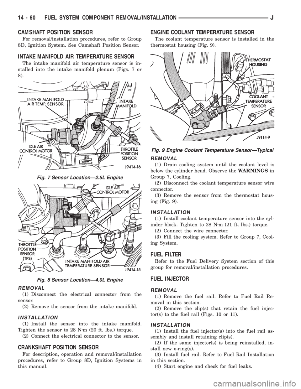
The intake manifold air temperature sensor is in-
stalled into the intake manifold plenum (Figs. 7 or
8).
REMOVAL
(1) Disconnect the electrical connector from the
sensor.
(2) Remove the sensor from the intake manifold.
INSTALLATION
(1) Install the sensor into the intake manifold.
Tighten the sensor to 28 Nzm (20 ft. lbs.) torque.
(2) Connect the electrical connector to the sensor.
CRANKSHAFT POSITION SENSOR
For description, operation and removal/installation
procedures, refer to Group 8D, Ignition Systems in
this manual.
ENGINE COOLANT TEMPERATURE SENSOR
The coolant temperature sensor is installed in the
thermostat housing (Fig. 9).
REMOVAL
(1) Drain cooling system until the coolant level is
below the cylinder head. Observe theWARNINGSin
Group 7, Cooling.
(2) Disconnect the coolant temperature sensor wire
connector.
(3) Remove the sensor from the thermostat hous-
ing (Fig. 9).
INSTALLATION
(1) Install coolant temperature sensor into the cyl-
inder block. Tighten to 28 Nzm (21 ft. lbs.) torque.
(2) Connect the wire connector.
(3) Fill the cooling system. Refer to Group 7, Cool-
ing System.
FUEL FILTER
Refer to the Fuel Delivery System section of this
group for removal/installation procedures.
FUEL INJECTOR
REMOVAL
(1) Remove the fuel rail. Refer to Fuel Rail Re-
moval in this section.
(2) Remove the clip(s) that retain the fuel injec-
tor(s) to the fuel rail (Figs. 10 or 11).
INSTALLATION
(1) Install the fuel injector(s) into the fuel rail as-
sembly and install retaining clip(s).
(2) If the same injector(s) is being reinstalled, in-
stall new o-ring(s).
(3) Install fuel rail. Refer to Fuel Rail Installation
in this section.
(4) Start engine and check for fuel leaks.
Fig. 7 Sensor LocationÐ2.5L Engine
Fig. 8 Sensor LocationÐ4.0L Engine
Fig. 9 Engine Coolant Temperature SensorÐTypical
14 - 60 FUEL SYSTEM COMPONENT REMOVAL/INSTALLATIONJ
Page 1276 of 2198

FUEL PUMP MODULE
Refer to the Fuel Delivery System section of this
group for removal/installation procedures.
FUEL PUMP RELAY
The fuel pump relay is located in the power distri-
bution center (PDC) (Figs. 1 or 2). For location of this
relay within the PDC, refer to label on PDC cover.
FUEL PRESSURE REGULATOR
WARNING: THE FUEL SYSTEM IS UNDER A CON-
STANT PRESSURE (EVEN WITH THE ENGINE
TURNED OFF). BEFORE SERVICING THE FUEL
PRESSURE REGULATOR, THE FUEL SYSTEM
PRESSURE MUST BE RELEASED.To release fuel pressure, refer to the Fuel Delivery
System section of this group. See Fuel System Pres-
sure Release.
REMOVAL
The fuel pressure regulator is located at the front
of the fuel rail (Fig 12). It is held to the fuel rail
(mounted vertically) with a clamp and bolt (Fig. 13).
(1) Perform the fuel pressure release procedure.
(2) Remove the vacuum line from the pressure reg-
ulator.
(3) Remove the clamp mounting bolt and regulator
mounting clamp from the fuel rail (Fig. 13).
(4) Remove pressure regulator from fuel rail.
(5) Remove and discard the o-ring seals.
INSTALLATION
(1) Install new o-ring seals to pressure regulator.
(2) Install pressure regulator to fuel rail.
(3) Install retaining clamp and clamp bolt.
(4) Install vacuum line to pressure regulator.
(5) Start engine and check for leaks.
Fig. 10 Injector Mounting
Fig. 11 Injector Retaining ClipsÐTypical Injector
Fig. 12 Fuel Injector HarnessÐTypical
Fig. 13 Fuel Rail AssemblyÐTypical
JFUEL SYSTEM COMPONENT REMOVAL/INSTALLATION 14 - 61
Page 1277 of 2198
FUEL RAIL ASSEMBLY
REMOVAL
WARNING: THE FUEL SYSTEM IS UNDER CON-
STANT FUEL PRESSURE (EVEN WITH THE ENGINE
OFF) OF APPROXIMATELY 131-269 KPA (19-39 PSI).
THIS PRESSURE MUST BE RELEASED BEFORE
SERVICING THE FUEL RAIL.
(1) Remove fuel tank filler tube cap.
(2) Disconnect the negative battery cable from bat-
tery.
(3) Perform the Fuel System Pressure Release Pro-
cedure as described in the Fuel Delivery System sec-
tion of this Group.
(4) Remove and numerically attach a tag (if fuel
injector is not already tagged), the injector harness
connectors. Do this at each injector (Fig. 12).
(5) Disconnect vacuum line from fuel pressure reg-
ulator (Fig. 12).
(6) Disconnect fuel supply line from fuel rail and
the fuel return line from fuel pressure regulator (Fig.
12). Refer to Fuel Tubes/Lines/Hoses and Clamps, or
Quick-Connect Fittings. These can both be found in
the Fuel Delivery section of this group.
(7) Remove fuel rail mounting bolts.
On models with automatic transmissions, it may be
necessary to remove automatic transmission throttle
line pressure cable and bracket. This will aid in fuel
rail assembly removal.
(8) Remove fuel rail by gently rocking until all the
fuel injectors are out of the intake manifold.
INSTALLATION
(1) Position tips of all fuel injectors into the corre-
sponding injector bore in the intake manifold. Seat
injectors into manifold.
(2) Tighten fuel rail mounting bolts to 27 Nzm (20
ft. lbs.) torque.
(3) Connect injector harness connectors to appro-
priate (tagged) injector.
(4) Connect both fuel lines to fuel rail. Refer to the
Fuel Delivery section of this group for procedures.
(5) Connect vacuum supply line to fuel pressure
regulator.
(6) Install protective cap to pressure test port fit-
ting.
(7) Install fuel tank cap.
(8) Connect negative battery cable to battery.
(9) Start engine and check for fuel leaks.
FUEL SYSTEM PRESSURE RELEASE PROCEDURE
WARNING: THE FUEL SYSTEM IS UNDER A CON-
STANT PRESSURE (EVEN WITH THE ENGINE OFF)
OF APPROXIMATELY 100 KPA (14.5 PSI). BEFORE
SERVICING THE FUEL PUMP, FUEL RAIL, FUELLINES, FUEL FILTER OR FUEL INJECTOR, THE
FUEL SYSTEM PRESSURE MUST BE RELEASED.
Refer to the Fuel Delivery System section of this
group. See Fuel Pressure Release procedure.
FUEL TANKS
Refer to the Fuel Tank section of this group for re-
moval/installation procedures.
FUEL TANK PRESSURE RELIEF/ROLLOVER VALVE
Refer to the Fuel Tank section of this group for re-
moval/installation procedures.
FUEL TUBES/LINES/HOSES AND CLAMPS
Refer to the Fuel Delivery System section of this
group for removal/installation procedures. Also refer
to Quick-Connect Fittings in the Fuel Delivery sec-
tion of this group.
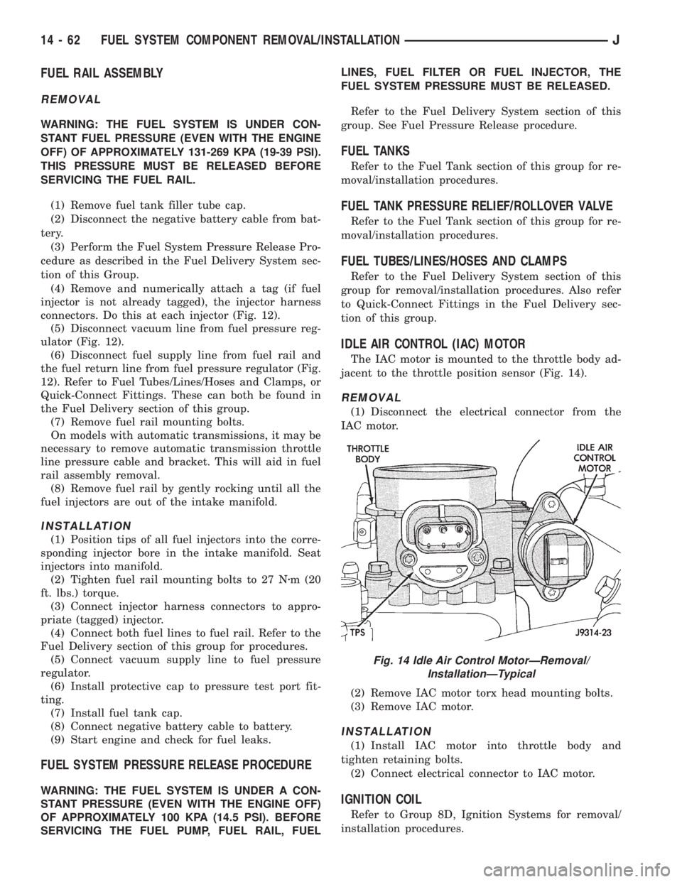
IDLE AIR CONTROL (IAC) MOTOR
The IAC motor is mounted to the throttle body ad-
jacent to the throttle position sensor (Fig. 14).
REMOVAL
(1) Disconnect the electrical connector from the
IAC motor.
(2) Remove IAC motor torx head mounting bolts.
(3) Remove IAC motor.
INSTALLATION
(1) Install IAC motor into throttle body and
tighten retaining bolts.
(2) Connect electrical connector to IAC motor.
IGNITION COIL
Refer to Group 8D, Ignition Systems for removal/
installation procedures.
Fig. 14 Idle Air Control MotorÐRemoval/
InstallationÐTypical
14 - 62 FUEL SYSTEM COMPONENT REMOVAL/INSTALLATIONJ
Page 1278 of 2198
INTAKE MANIFOLD
Refer to Group 11, Exhaust System and Intake
Manifold for removal/installation procedures.
MANIFOLD ABSOLUTE PRESSURE (MAP) SENSOR
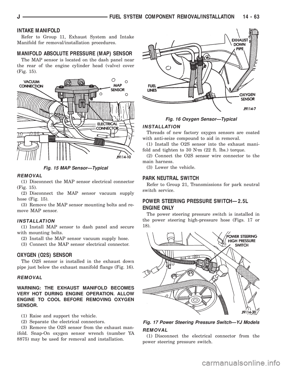
The MAP sensor is located on the dash panel near
the rear of the engine cylinder head (valve) cover
(Fig. 15).
REMOVAL
(1) Disconnect the MAP sensor electrical connector
(Fig. 15).
(2) Disconnect the MAP sensor vacuum supply
hose (Fig. 15).
(3) Remove the MAP sensor mounting bolts and re-
move MAP sensor.
INSTALLATION
(1) Install MAP sensor to dash panel and secure
with mounting bolts.
(2) Install the MAP sensor vacuum supply hose.
(3) Connect the MAP sensor electrical connector.
OXYGEN (O2S) SENSOR
The O2S sensor is installed in the exhaust down
pipe just below the exhaust manifold flange (Fig. 16).
REMOVAL
WARNING: THE EXHAUST MANIFOLD BECOMES
VERY HOT DURING ENGINE OPERATION. ALLOW
ENGINE TO COOL BEFORE REMOVING OXYGEN
SENSOR.
(1) Raise and support the vehicle.
(2) Separate the electrical connectors.
(3) Remove the O2S sensor from the exhaust man-
ifold. Snap-On oxygen sensor wrench (number YA
8875) may be used for removal and installation.
INSTALLATION
Threads of new factory oxygen sensors are coated
with anti-seize compound to aid in removal.
(1) Install the O2S sensor into the exhaust mani-
fold and tighten to 30 Nzm (22 ft. lbs.) torque.
(2) Connect the O2S sensor wire connector to the
main harness.
(3) Lower the vehicle.
PARK NEUTRAL SWITCH
Refer to Group 21, Transmissions for park neutral
switch service.
POWER STEERING PRESSURE SWITCHÐ2.5L
ENGINE ONLY
The power steering pressure switch is installed in
the power steering high-pressure hose (Figs. 17 or
18).
REMOVAL
(1) Disconnect the electrical connector from the
power steering pressure switch.
Fig. 15 MAP SensorÐTypical
Fig. 16 Oxygen SensorÐTypical
Fig. 17 Power Steering Pressure SwitchÐYJ Models
JFUEL SYSTEM COMPONENT REMOVAL/INSTALLATION 14 - 63
Page 1279 of 2198
(2) Place a small container or shop towel beneath
the switch to collect any excess fluid.
(3) Remove the switch.
INSTALLATION
(1) Install the power steering switch.
(2) Connect the electrical connector to the switch.
(3) Check power steering fluid and add as neces-
sary.
(4) Start the engine and again check power steer-
ing fluid. Add fluid if necessary.
POWERTRAIN CONTROL MODULE (PCM)
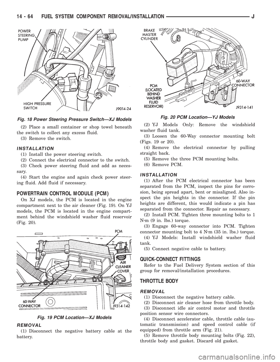
On XJ models, the PCM is located in the engine
compartment next to the air cleaner (Fig. 19). On YJ
models, the PCM is located in the engine compart-
ment behind the windshield washer fluid reservoir
(Fig. 20).
REMOVAL
(1) Disconnect the negative battery cable at the
battery.(2) YJ Models Only: Remove the windshield
washer fluid tank.
(3) Loosen the 60-Way connector mounting bolt
(Figs. 19 or 20).
(4) Remove the electrical connector by pulling
straight back.
(5) Remove the three PCM mounting bolts.
(6) Remove PCM.
INSTALLATION
(1) After the PCM electrical connector has been
separated from the PCM, inspect the pins for corro-
sion, being spread apart, bent or misaligned. Also in-
spect the pin heights in the connector. If the pin
heights are different, this would indicate a pin has
separated from the connector. Repair as necessary.
(2) Install PCM. Tighten three mounting bolts to 1
Nzm (9 in. lbs.) torque.
(3) Engage 60-way connector into PCM. Tighten
connector mounting bolt to 4 Nzm (35 in. lbs.) torque.
(4) YJ Models: Install windshield washer fluid
tank.
(5) Connect negative cable to battery.
QUICK-CONNECT FITTINGS
Refer to the Fuel Delivery System section of this
group for removal/installation procedures.
THROTTLE BODY
REMOVAL
(1) Disconnect the negative battery cable.
(2) Disconnect air cleaner hose from throttle body.
(3) Disconnect idle air control motor and throttle
position sensor wire connectors.
(4) Disconnect accelerator cable, throttle cable (au-
tomatic transmission) and speed control cable (if
equipped) from throttle arm (Fig. 21).
(5) Remove throttle body mounting bolts (Fig. 22),
throttle body and gasket. Discard old gasket.
Fig. 18 Power Steering Pressure SwitchÐXJ Models
Fig. 19 PCM LocationÐXJ Models
Fig. 20 PCM LocationÐYJ Models
14 - 64 FUEL SYSTEM COMPONENT REMOVAL/INSTALLATIONJ
Page 1280 of 2198

INSTALLATION
(1) Install throttle body and new gasket. Tighten
throttle body mounting bolts to 12 Nzm (9 ft. lbs.)
torque.
(2) Connect idle air control motor and throttle po-
sition sensor wire connectors.
(3) Connect throttle linkage to throttle arm.
CAUTION: When the automatic transmission throttle
cable is connected, it MUST be adjusted.
(4) If equipped with an automatic transmission,
connect and adjust the transmission line pressure ca-
ble. Refer to Group 21, Transmissions for adjustment
procedure.
(5) Install air cleaner hose to throttle body.
(6) Connect negative battery cable to battery.
THROTTLE POSITION SENSOR (TPS)
The TPS is mounted to the throttle body (Figs. 23
or 24).
REMOVAL
(1) Disconnect TPS electrical connector.
(2) Remove TPS mounting bolts.
(3) Remove TPS.
INSTALLATION
The throttle shaft end of the throttle body slides
into a socket in the TPS (Fig. 25). The TPS must be
installed so that it can be rotated a few degrees. (If
the sensor will not rotate, install the sensor with the
throttle shaft on the other side of the socket tangs).
The TPS will be under slight tension when rotated.
(1) Install the TPS and retaining bolts.
(2) Connect TPS electrical connector to TPS.
(3) Manually operate the throttle (by hand) to
check for any TPS binding before starting the engine.
TORQUE CONVERTER CLUTCH RELAY
On YJ models, the TCC relay is located in the en-
gine compartment. It is attached to the cowl panel
with one bolt (Fig. 26). On XJ models, the TCC relay
is located in the power distribution center (PDC)
Fig. 21 Cables at Throttle Body
Fig. 22 Throttle BodyÐRemoval/InstallationÐ
Typical
Fig. 23 TPS LocationÐ2.5L Engine
Fig. 24 TPS LocationÐ4.0L Engine
JFUEL SYSTEM COMPONENT REMOVAL/INSTALLATION 14 - 65