JEEP CHEROKEE 1995 Service Repair Manual
Manufacturer: JEEP, Model Year: 1995, Model line: CHEROKEE, Model: JEEP CHEROKEE 1995Pages: 2198, PDF Size: 82.83 MB
Page 1501 of 2198
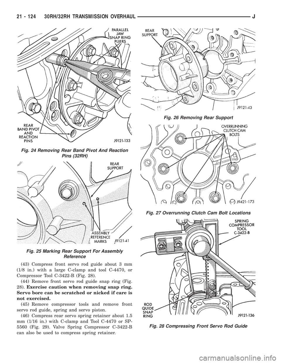
(43) Compress front servo rod guide about 3 mm
(1/8 in.) with a large C-clamp and tool C-4470, or
Compressor Tool C-3422-B (Fig. 28).
(44) Remove front servo rod guide snap ring (Fig.
28).Exercise caution when removing snap ring.
Servo bore can be scratched or nicked if care is
not exercised.
(45) Remove compressor tools and remove front
servo rod guide, spring and servo piston.
(46) Compress rear servo spring retainer about 1.5
mm (1/16 in.) with C-clamp and Tool C-4470 or SP-
5560 (Fig. 29). Valve Spring Compressor C-3422-B
can also be used to compress spring retainer.
Fig. 24 Removing Rear Band Pivot And Reaction
Pins (32RH)
Fig. 25 Marking Rear Support For Assembly
Reference
Fig. 26 Removing Rear Support
Fig. 27 Overrunning Clutch Cam Bolt Locations
Fig. 28 Compressing Front Servo Rod Guide
21 - 124 30RH/32RH TRANSMISSION OVERHAULJ
Page 1502 of 2198
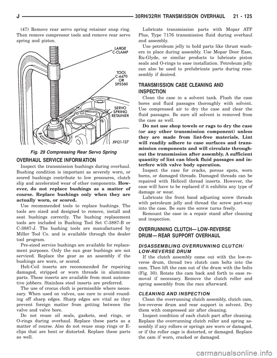
(47) Remove rear servo spring retainer snap ring.
Then remove compressor tools and remove rear servo
spring and piston.
OVERHAUL SERVICE INFORMATION
Inspect the transmission bushings during overhaul.
Bushing condition is important as severely worn, or
scored bushings contribute to low pressures, clutch
slip and accelerated wear of other components.How-
ever, do not replace bushings as a matter of
course. Replace bushings only when they are
actually worn, or scored.
Use recommended tools to replace bushings. The
tools are sized and designed to remove, install and
seat bushings correctly. The bushing replacement
tools are included in Bushing Tool Set C-3887-B or
C-3887-J. The bushing tools are manufactured by
Miller Tool Co. and is available through the dealer
tool program.
Pre-sized service bushings are available for replace-
ment purposes. Only the sun gear bushings are not
serviced. Replace the gear as an assembly if the
bushings are worn, or scored.
Heli-Coil inserts are recommended for repairing
damaged, stripped or worn threads in aluminum
parts. These inserts are available from most automo-
tive jobbers. Stainless steel inserts are preferred.
The use of crocus cloth is permissible where neces-
sary. When used on valves, use care to avoid round-
ing off sharp edges. Sharp edges are vital as they
prevent foreign matter from getting between the
valve and valve bore.
Do not reuse oil seals, gaskets, seal rings, or
O-rings during overhaul. Replace these parts as a
matter of course. Also do not reuse snap rings or E-
clips that are bent or distorted. Replace these parts
as well.Lubricate transmission parts with Mopar ATF
Plus, Type 7176 transmission fluid during overhaul
and assembly.
Use petroleum jelly to hold parts like thrust wash-
ers in place during assembly. Use Mopar Door Ease,
Ru-Glyde, or similar products to lubricate piston
seals and O-rings to ease installation. Petroleum jelly
can also be used to prelubricate parts during reas-
sembly if desired.
TRANSMISSION CASE CLEANING AND
INSPECTION
Clean the case in a solvent tank. Flush the case
bores and fluid passages thoroughly with solvent.
Use compressed air to dry the case and clear the
fluid passages. Be sure all solvent is removed from
the case as well.
Do not use shop towels or rags to dry the case
(or any other transmission component) unless
they are made from lint-free materials. Lint
will readily adhere to case surfaces and trans-
mission components and will circulate through-
out the transmission after assembly. A sufficient
quantity of lint can block fluid passages and in-
terfere with valve body operation.
Inspect the case for cracks, porous spots, worn
bores, or damaged threads. Damaged threads can be
repaired with Helicoil thread inserts. However, the
case will have to be replaced if it exhibits any type of
damage or wear.
Lubricate the front band adjusting screw threads
with petroleum jelly and thread the screw part-way
into the case. Be sure the screw turns freely.
Remount the case in a repair stand after cleaning
and inspection.
OVERRUNNING CLUTCHÐLOW-REVERSE
DRUMÐREAR SUPPORT OVERHAUL
DISASSEMBLING OVERRUNNING CLUTCH/
LOW-REVERSE DRUM
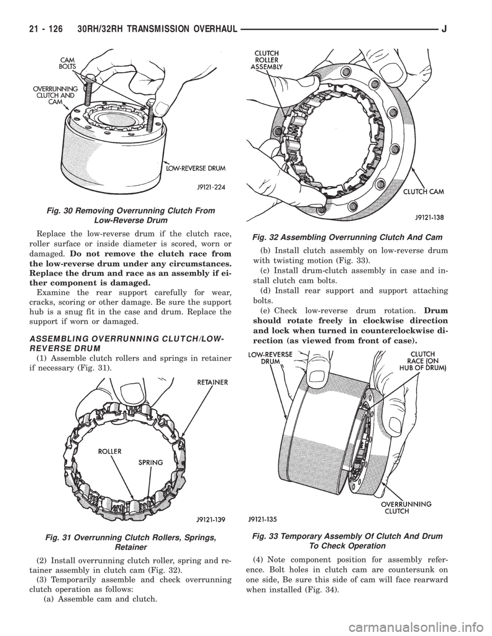
If the clutch assembly came out with the low-re-
verse drum, thread two clutch cam bolts into the
cam. Then lift the cam out of the drum with the bolts
(Fig. 30). Rotate the cam back and forth to ease re-
moval if necessary. Remove the clutch roller and
spring assembly from the race afterward.
CLEANING AND INSPECTION
Clean the overrunning clutch assembly, clutch cam,
low-reverse drum and rear support in solvent. Dry
them with compressed air after cleaning.
Inspect condition of each clutch part after cleaning.
Replace the overrunning clutch roller and spring as-
sembly if any rollers or springs are worn or damaged,
or if the roller cage is distorted, or damaged. Replace
the cam if worn, cracked or damaged.
Fig. 29 Compressing Rear Servo Spring
J30RH/32RH TRANSMISSION OVERHAUL 21 - 125
Page 1503 of 2198
Replace the low-reverse drum if the clutch race,
roller surface or inside diameter is scored, worn or
damaged.Do not remove the clutch race from
the low-reverse drum under any circumstances.
Replace the drum and race as an assembly if ei-
ther component is damaged.
Examine the rear support carefully for wear,
cracks, scoring or other damage. Be sure the support
hub is a snug fit in the case and drum. Replace the
support if worn or damaged.
ASSEMBLING OVERRUNNING CLUTCH/LOW-
REVERSE DRUM
(1) Assemble clutch rollers and springs in retainer
if necessary (Fig. 31).
(2) Install overrunning clutch roller, spring and re-
tainer assembly in clutch cam (Fig. 32).
(3) Temporarily assemble and check overrunning
clutch operation as follows:
(a) Assemble cam and clutch.(b) Install clutch assembly on low-reverse drum
with twisting motion (Fig. 33).
(c) Install drum-clutch assembly in case and in-
stall clutch cam bolts.
(d) Install rear support and support attaching
bolts.
(e) Check low-reverse drum rotation.Drum
should rotate freely in clockwise direction
and lock when turned in counterclockwise di-
rection (as viewed from front of case).
(4) Note component position for assembly refer-
ence. Bolt holes in clutch cam are countersunk on
one side, Be sure this side of cam will face rearward
when installed (Fig. 34).
Fig. 30 Removing Overrunning Clutch From
Low-Reverse Drum
Fig. 31 Overrunning Clutch Rollers, Springs,
Retainer
Fig. 32 Assembling Overrunning Clutch And Cam
Fig. 33 Temporary Assembly Of Clutch And Drum
To Check Operation
21 - 126 30RH/32RH TRANSMISSION OVERHAULJ
Page 1504 of 2198
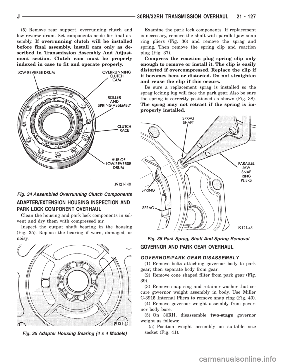
(5) Remove rear support, overrunning clutch and
low-reverse drum. Set components aside for final as-
sembly.If overrunning clutch will be installed
before final assembly, install cam only as de-
scribed in Transmission Assembly And Adjust-
ment section. Clutch cam must be properly
indexed in case to fit and operate properly.
ADAPTER/EXTENSION HOUSING INSPECTION AND
PARK LOCK COMPONENT OVERHAUL
Clean the housing and park lock components in sol-
vent and dry them with compressed air.
Inspect the output shaft bearing in the housing
(Fig. 35). Replace the bearing if worn, damaged, or
noisy.Examine the park lock components. If replacement
is necessary, remove the shaft with parallel jaw snap
ring pliers (Fig. 36) and remove the sprag and
spring. Then remove the spring clip and reaction
plug (Fig. 37).
Compress the reaction plug spring clip only
enough to remove or install it. The clip is easily
distorted if overcompressed. Replace the clip if
it becomes bent or distorted. Do not straighten
and reuse the clip if this occurs.
Be sure a replacement sprag is installed so the
sprag locking lug will face the park gear. Also be sure
the spring is correctly positioned as shown (Fig. 38).
The sprag may not retract if the spring is im-
properly installed.
GOVERNOR AND PARK GEAR OVERHAUL
GOVERNOR/PARK GEAR DISASSEMBLY
(1) Remove bolts attaching governor body to park
gear; then separate body from gear.
(2) Remove cone shaped filter from park gear (Fig.
39).
(3) Remove snap ring and retainer washer that se-
cure governor weight assembly in body. Use Miller
C-3915 Internal Pliers to remove snap ring (Fig. 40).
(4) Remove governor weight assembly from gover-
nor body bore.
(5) On 30RH, disassembletwo-stagegovernor
weight as follows:
(a) Position weight assembly on suitable size
socket (Fig. 41).
Fig. 34 Assembled Overrunning Clutch Components
Fig. 35 Adapter Housing Bearing (4 x 4 Models)
Fig. 36 Park Sprag, Shaft And Spring Removal
J30RH/32RH TRANSMISSION OVERHAUL 21 - 127
Page 1505 of 2198
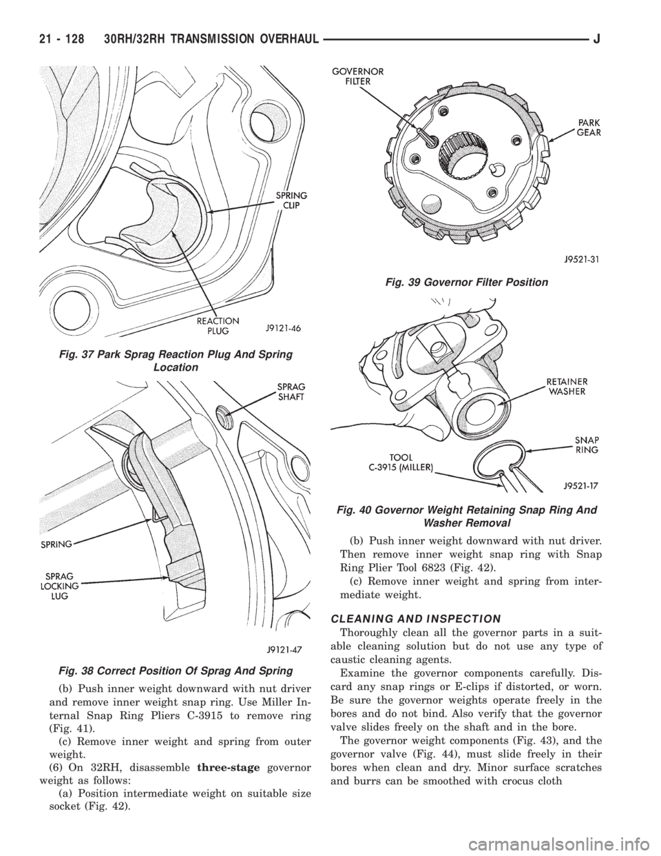
(b) Push inner weight downward with nut driver
and remove inner weight snap ring. Use Miller In-
ternal Snap Ring Pliers C-3915 to remove ring
(Fig. 41).
(c) Remove inner weight and spring from outer
weight.
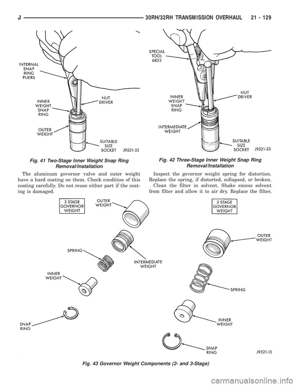
(6) On 32RH, disassemblethree-stagegovernor
weight as follows:
(a) Position intermediate weight on suitable size
socket (Fig. 42).(b) Push inner weight downward with nut driver.
Then remove inner weight snap ring with Snap
Ring Plier Tool 6823 (Fig. 42).
(c) Remove inner weight and spring from inter-
mediate weight.
CLEANING AND INSPECTION
Thoroughly clean all the governor parts in a suit-
able cleaning solution but do not use any type of
caustic cleaning agents.
Examine the governor components carefully. Dis-
card any snap rings or E-clips if distorted, or worn.
Be sure the governor weights operate freely in the
bores and do not bind. Also verify that the governor
valve slides freely on the shaft and in the bore.
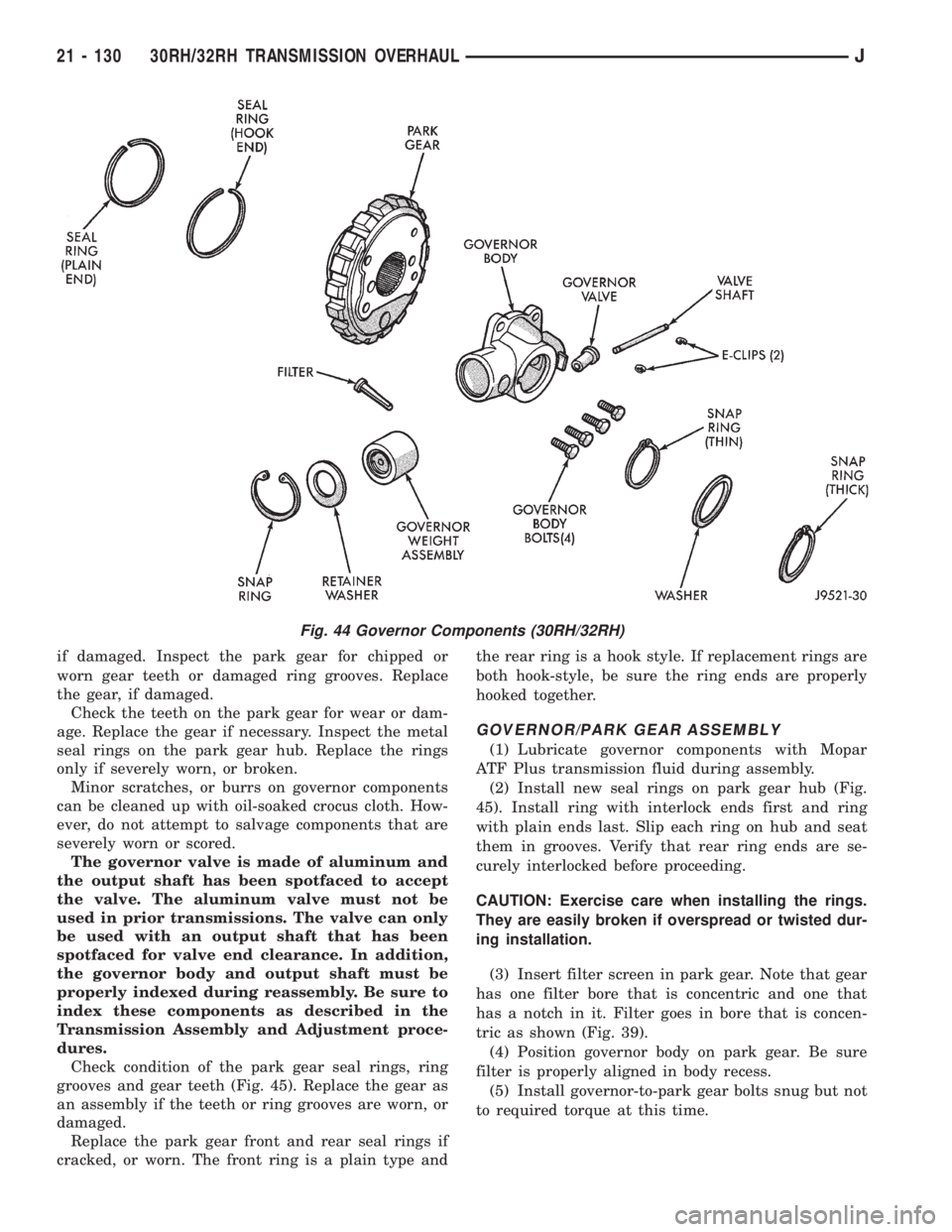
The governor weight components (Fig. 43), and the
governor valve (Fig. 44), must slide freely in their
bores when clean and dry. Minor surface scratches
and burrs can be smoothed with crocus cloth
Fig. 37 Park Sprag Reaction Plug And Spring
Location
Fig. 38 Correct Position Of Sprag And Spring
Fig. 39 Governor Filter Position
Fig. 40 Governor Weight Retaining Snap Ring And
Washer Removal
21 - 128 30RH/32RH TRANSMISSION OVERHAULJ
Page 1506 of 2198
The aluminum governor valve and outer weight
have a hard coating on them. Check condition of this
coating carefully. Do not reuse either part if the coat-
ing is damaged.Inspect the governor weight spring for distortion.
Replace the spring, if distorted, collapsed, or broken.
Clean the filter in solvent. Shake excess solvent
from filter and allow it to air dry. Replace the filter,
Fig. 41 Two-Stage Inner Weight Snap Ring
Removal/InstallationFig. 42 Three-Stage Inner Weight Snap Ring
Removal/Installation
Fig. 43 Governor Weight Components (2- and 3-Stage)
J30RH/32RH TRANSMISSION OVERHAUL 21 - 129
Page 1507 of 2198
if damaged. Inspect the park gear for chipped or
worn gear teeth or damaged ring grooves. Replace
the gear, if damaged.
Check the teeth on the park gear for wear or dam-
age. Replace the gear if necessary. Inspect the metal
seal rings on the park gear hub. Replace the rings
only if severely worn, or broken.
Minor scratches, or burrs on governor components
can be cleaned up with oil-soaked crocus cloth. How-
ever, do not attempt to salvage components that are
severely worn or scored.
The governor valve is made of aluminum and
the output shaft has been spotfaced to accept
the valve. The aluminum valve must not be
used in prior transmissions. The valve can only
be used with an output shaft that has been
spotfaced for valve end clearance. In addition,
the governor body and output shaft must be
properly indexed during reassembly. Be sure to
index these components as described in the
Transmission Assembly and Adjustment proce-
dures.
Check condition of the park gear seal rings, ring
grooves and gear teeth (Fig. 45). Replace the gear as
an assembly if the teeth or ring grooves are worn, or
damaged.
Replace the park gear front and rear seal rings if
cracked, or worn. The front ring is a plain type andthe rear ring is a hook style. If replacement rings are
both hook-style, be sure the ring ends are properly
hooked together.
GOVERNOR/PARK GEAR ASSEMBLY
(1) Lubricate governor components with Mopar
ATF Plus transmission fluid during assembly.
(2) Install new seal rings on park gear hub (Fig.
45). Install ring with interlock ends first and ring
with plain ends last. Slip each ring on hub and seat
them in grooves. Verify that rear ring ends are se-
curely interlocked before proceeding.
CAUTION: Exercise care when installing the rings.
They are easily broken if overspread or twisted dur-
ing installation.
(3) Insert filter screen in park gear. Note that gear
has one filter bore that is concentric and one that
has a notch in it. Filter goes in bore that is concen-
tric as shown (Fig. 39).
(4) Position governor body on park gear. Be sure
filter is properly aligned in body recess.
(5) Install governor-to-park gear bolts snug but not
to required torque at this time.
Fig. 44 Governor Components (30RH/32RH)
21 - 130 30RH/32RH TRANSMISSION OVERHAULJ
Page 1508 of 2198
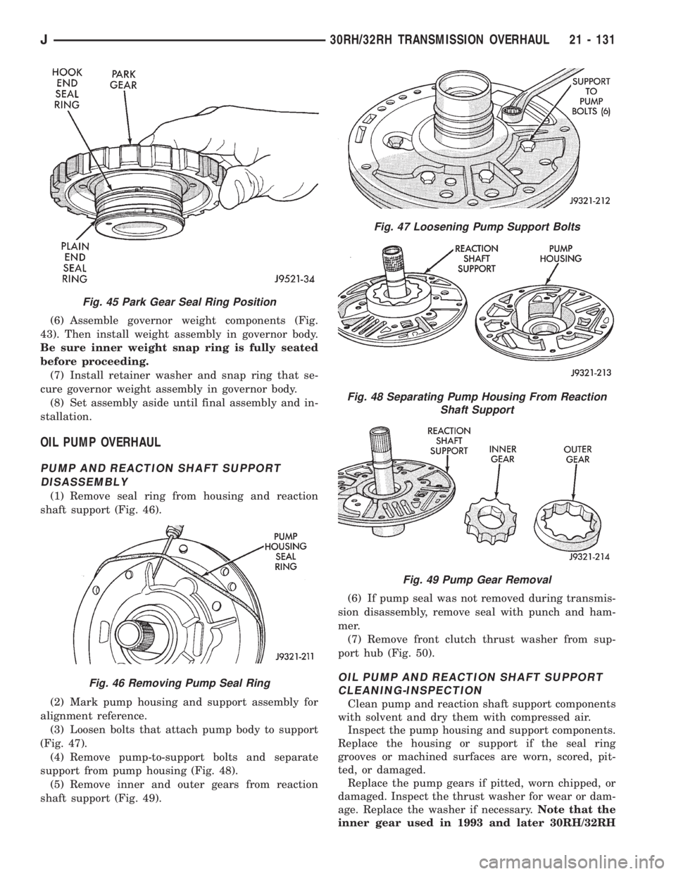
(6) Assemble governor weight components (Fig.
43). Then install weight assembly in governor body.
Be sure inner weight snap ring is fully seated
before proceeding.
(7) Install retainer washer and snap ring that se-
cure governor weight assembly in governor body.
(8) Set assembly aside until final assembly and in-
stallation.
OIL PUMP OVERHAUL
PUMP AND REACTION SHAFT SUPPORT
DISASSEMBLY
(1) Remove seal ring from housing and reaction
shaft support (Fig. 46).
(2) Mark pump housing and support assembly for
alignment reference.
(3) Loosen bolts that attach pump body to support
(Fig. 47).
(4) Remove pump-to-support bolts and separate
support from pump housing (Fig. 48).
(5) Remove inner and outer gears from reaction
shaft support (Fig. 49).(6) If pump seal was not removed during transmis-
sion disassembly, remove seal with punch and ham-
mer.
(7) Remove front clutch thrust washer from sup-
port hub (Fig. 50).
OIL PUMP AND REACTION SHAFT SUPPORT
CLEANING-INSPECTION
Clean pump and reaction shaft support components
with solvent and dry them with compressed air.
Inspect the pump housing and support components.
Replace the housing or support if the seal ring
grooves or machined surfaces are worn, scored, pit-
ted, or damaged.
Replace the pump gears if pitted, worn chipped, or
damaged. Inspect the thrust washer for wear or dam-
age. Replace the washer if necessary.Note that the
inner gear used in 1993 and later 30RH/32RH
Fig. 45 Park Gear Seal Ring Position
Fig. 46 Removing Pump Seal Ring
Fig. 47 Loosening Pump Support Bolts
Fig. 48 Separating Pump Housing From Reaction
Shaft Support
Fig. 49 Pump Gear Removal
J30RH/32RH TRANSMISSION OVERHAUL 21 - 131
Page 1509 of 2198
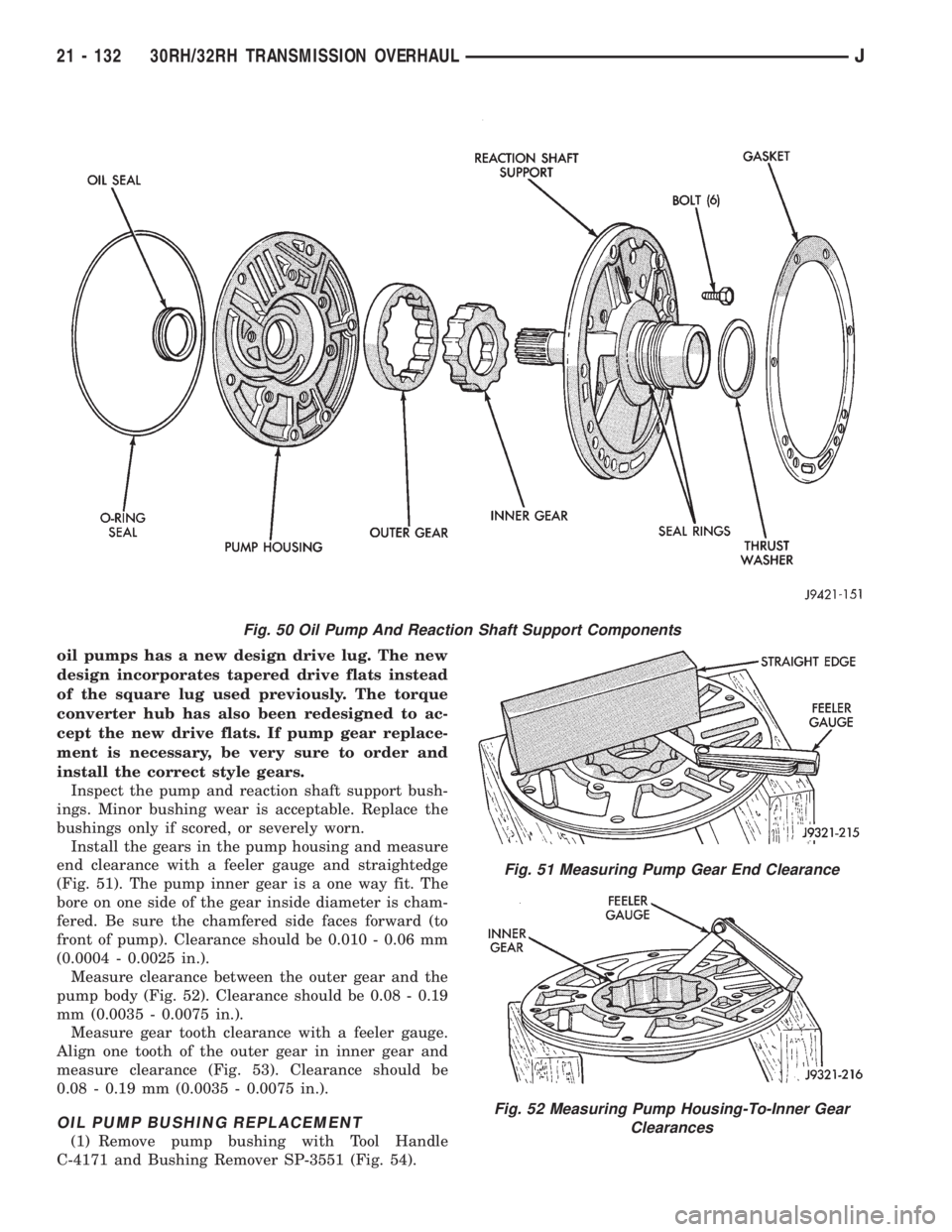
oil pumps has a new design drive lug. The new
design incorporates tapered drive flats instead
of the square lug used previously. The torque
converter hub has also been redesigned to ac-
cept the new drive flats. If pump gear replace-
ment is necessary, be very sure to order and
install the correct style gears.
Inspect the pump and reaction shaft support bush-
ings. Minor bushing wear is acceptable. Replace the
bushings only if scored, or severely worn.
Install the gears in the pump housing and measure
end clearance with a feeler gauge and straightedge
(Fig. 51). The pump inner gear is a one way fit. The
bore on one side of the gear inside diameter is cham-
fered. Be sure the chamfered side faces forward (to
front of pump). Clearance should be 0.010 - 0.06 mm
(0.0004 - 0.0025 in.).
Measure clearance between the outer gear and the
pump body (Fig. 52). Clearance should be 0.08 - 0.19
mm (0.0035 - 0.0075 in.).
Measure gear tooth clearance with a feeler gauge.
Align one tooth of the outer gear in inner gear and
measure clearance (Fig. 53). Clearance should be
0.08 - 0.19 mm (0.0035 - 0.0075 in.).
OIL PUMP BUSHING REPLACEMENT
(1) Remove pump bushing with Tool Handle
C-4171 and Bushing Remover SP-3551 (Fig. 54).
Fig. 50 Oil Pump And Reaction Shaft Support Components
Fig. 51 Measuring Pump Gear End Clearance
Fig. 52 Measuring Pump Housing-To-Inner Gear
Clearances
21 - 132 30RH/32RH TRANSMISSION OVERHAULJ
Page 1510 of 2198
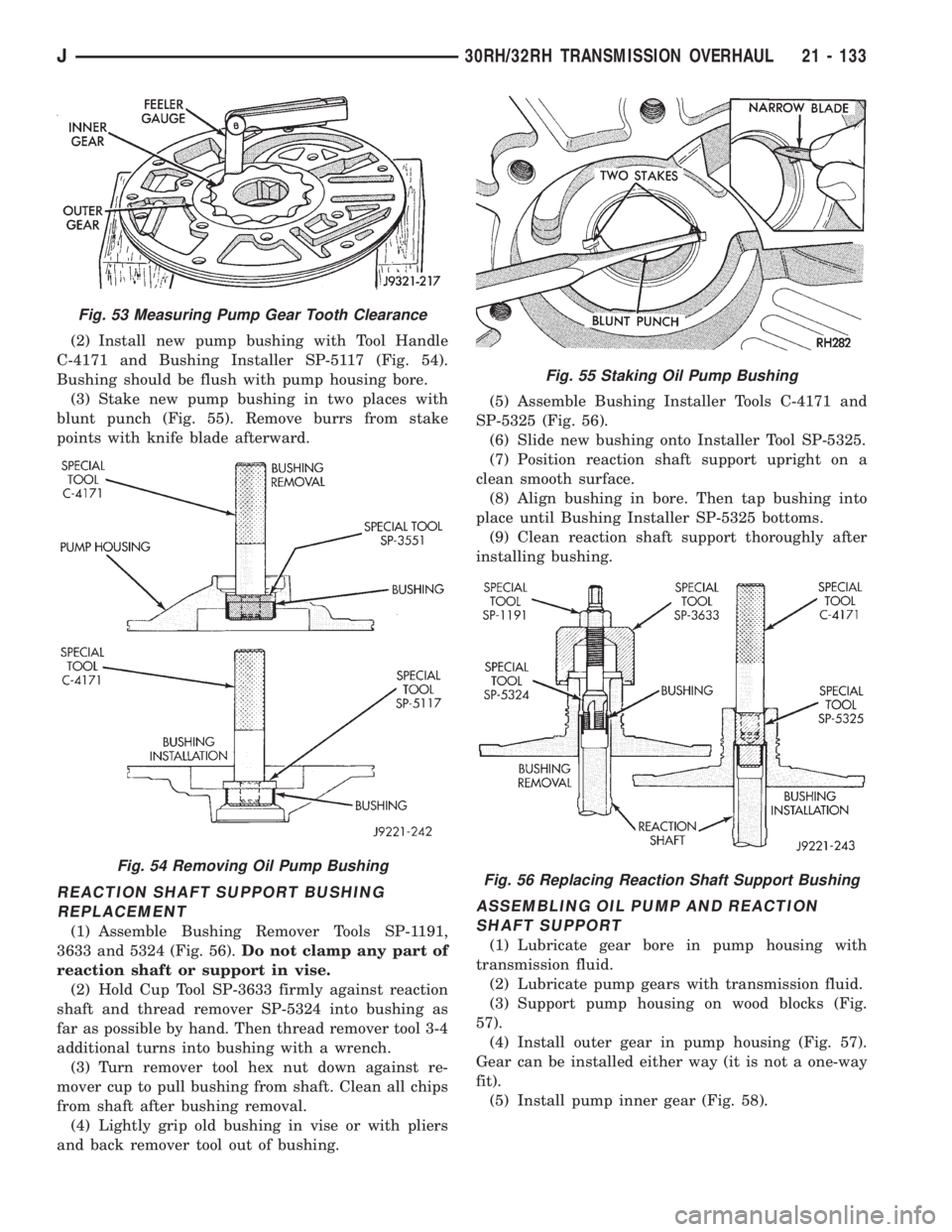
(2) Install new pump bushing with Tool Handle
C-4171 and Bushing Installer SP-5117 (Fig. 54).
Bushing should be flush with pump housing bore.
(3) Stake new pump bushing in two places with
blunt punch (Fig. 55). Remove burrs from stake
points with knife blade afterward.
REACTION SHAFT SUPPORT BUSHING
REPLACEMENT
(1) Assemble Bushing Remover Tools SP-1191,
3633 and 5324 (Fig. 56).Do not clamp any part of
reaction shaft or support in vise.
(2) Hold Cup Tool SP-3633 firmly against reaction
shaft and thread remover SP-5324 into bushing as
far as possible by hand. Then thread remover tool 3-4
additional turns into bushing with a wrench.
(3) Turn remover tool hex nut down against re-
mover cup to pull bushing from shaft. Clean all chips
from shaft after bushing removal.
(4) Lightly grip old bushing in vise or with pliers
and back remover tool out of bushing.(5) Assemble Bushing Installer Tools C-4171 and
SP-5325 (Fig. 56).
(6) Slide new bushing onto Installer Tool SP-5325.
(7) Position reaction shaft support upright on a
clean smooth surface.
(8) Align bushing in bore. Then tap bushing into
place until Bushing Installer SP-5325 bottoms.
(9) Clean reaction shaft support thoroughly after
installing bushing.
ASSEMBLING OIL PUMP AND REACTION
SHAFT SUPPORT
(1) Lubricate gear bore in pump housing with
transmission fluid.
(2) Lubricate pump gears with transmission fluid.
(3) Support pump housing on wood blocks (Fig.
57).
(4) Install outer gear in pump housing (Fig. 57).
Gear can be installed either way (it is not a one-way
fit).
(5) Install pump inner gear (Fig. 58).
Fig. 53 Measuring Pump Gear Tooth Clearance
Fig. 54 Removing Oil Pump Bushing
Fig. 55 Staking Oil Pump Bushing
Fig. 56 Replacing Reaction Shaft Support Bushing
J30RH/32RH TRANSMISSION OVERHAUL 21 - 133