JEEP CHEROKEE 1995 Service Repair Manual
Manufacturer: JEEP, Model Year: 1995, Model line: CHEROKEE, Model: JEEP CHEROKEE 1995Pages: 2198, PDF Size: 82.83 MB
Page 1521 of 2198
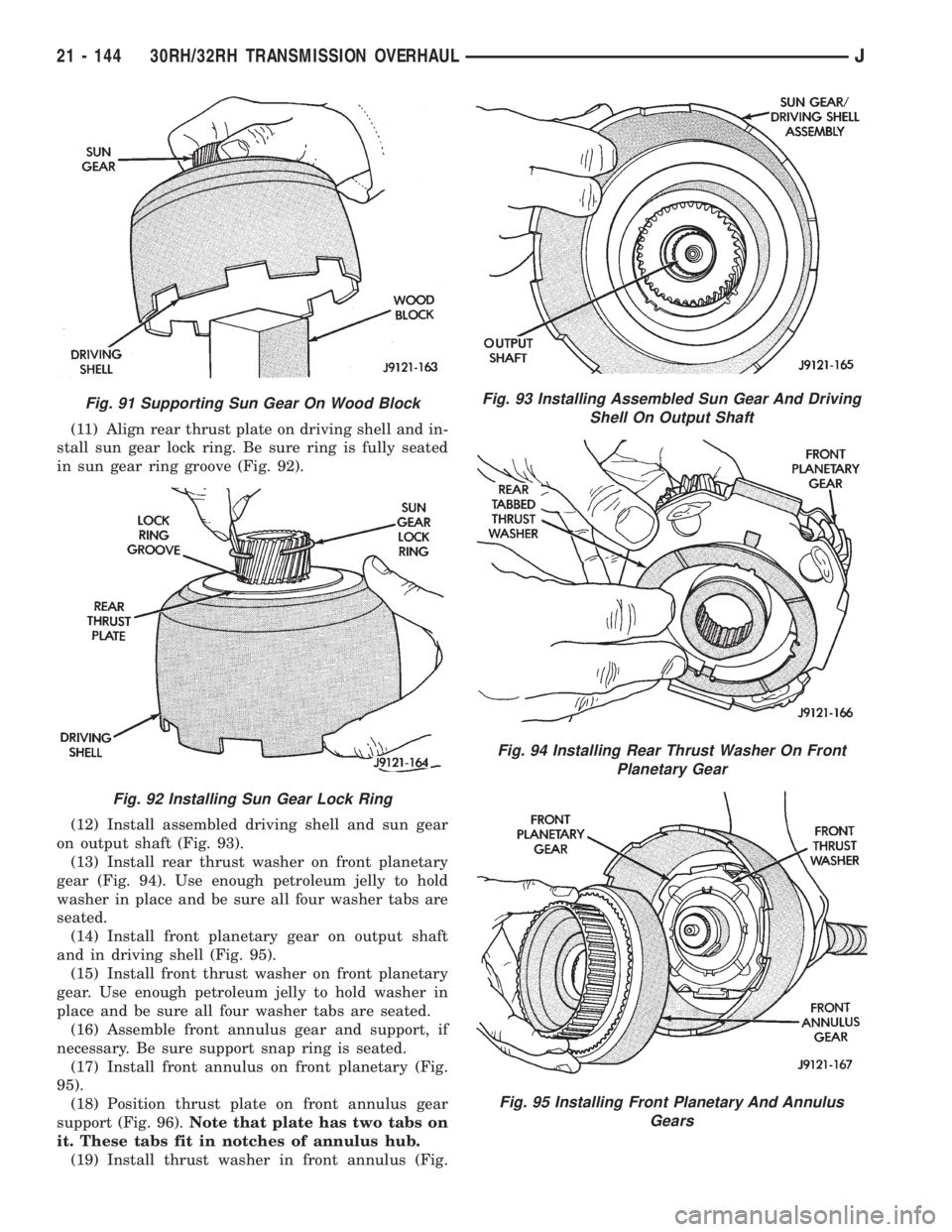
(11) Align rear thrust plate on driving shell and in-
stall sun gear lock ring. Be sure ring is fully seated
in sun gear ring groove (Fig. 92).
(12) Install assembled driving shell and sun gear
on output shaft (Fig. 93).
(13) Install rear thrust washer on front planetary
gear (Fig. 94). Use enough petroleum jelly to hold
washer in place and be sure all four washer tabs are
seated.
(14) Install front planetary gear on output shaft
and in driving shell (Fig. 95).
(15) Install front thrust washer on front planetary
gear. Use enough petroleum jelly to hold washer in
place and be sure all four washer tabs are seated.
(16) Assemble front annulus gear and support, if
necessary. Be sure support snap ring is seated.
(17) Install front annulus on front planetary (Fig.
95).
(18) Position thrust plate on front annulus gear
support (Fig. 96).Note that plate has two tabs on
it. These tabs fit in notches of annulus hub.
(19) Install thrust washer in front annulus (Fig.
Fig. 91 Supporting Sun Gear On Wood Block
Fig. 92 Installing Sun Gear Lock Ring
Fig. 93 Installing Assembled Sun Gear And Driving
Shell On Output Shaft
Fig. 94 Installing Rear Thrust Washer On Front
Planetary Gear
Fig. 95 Installing Front Planetary And Annulus
Gears
21 - 144 30RH/32RH TRANSMISSION OVERHAULJ
Page 1522 of 2198
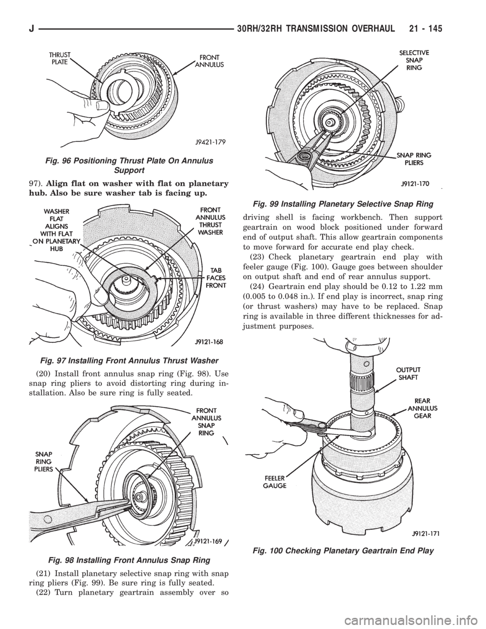
97).Align flat on washer with flat on planetary
hub. Also be sure washer tab is facing up.
(20) Install front annulus snap ring (Fig. 98). Use
snap ring pliers to avoid distorting ring during in-
stallation. Also be sure ring is fully seated.
(21) Install planetary selective snap ring with snap
ring pliers (Fig. 99). Be sure ring is fully seated.
(22) Turn planetary geartrain assembly over sodriving shell is facing workbench. Then support
geartrain on wood block positioned under forward
end of output shaft. This allow geartrain components
to move forward for accurate end play check.
(23) Check planetary geartrain end play with
feeler gauge (Fig. 100). Gauge goes between shoulder
on output shaft and end of rear annulus support.
(24) Geartrain end play should be 0.12 to 1.22 mm
(0.005 to 0.048 in.). If end play is incorrect, snap ring
(or thrust washers) may have to be replaced. Snap
ring is available in three different thicknesses for ad-
justment purposes.
Fig. 96 Positioning Thrust Plate On Annulus
Support
Fig. 97 Installing Front Annulus Thrust Washer
Fig. 98 Installing Front Annulus Snap Ring
Fig. 99 Installing Planetary Selective Snap Ring
Fig. 100 Checking Planetary Geartrain End Play
J30RH/32RH TRANSMISSION OVERHAUL 21 - 145
Page 1523 of 2198
FRONT SERVO AND BAND OVERHAUL
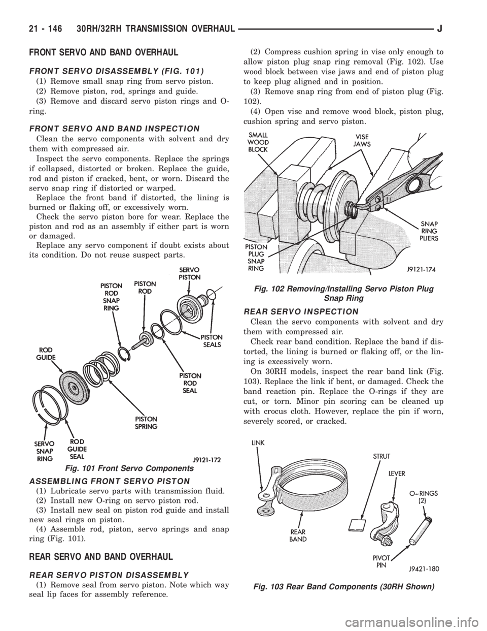
FRONT SERVO DISASSEMBLY (FIG. 101)
(1) Remove small snap ring from servo piston.
(2) Remove piston, rod, springs and guide.
(3) Remove and discard servo piston rings and O-
ring.
FRONT SERVO AND BAND INSPECTION
Clean the servo components with solvent and dry
them with compressed air.
Inspect the servo components. Replace the springs
if collapsed, distorted or broken. Replace the guide,
rod and piston if cracked, bent, or worn. Discard the
servo snap ring if distorted or warped.
Replace the front band if distorted, the lining is
burned or flaking off, or excessively worn.
Check the servo piston bore for wear. Replace the
piston and rod as an assembly if either part is worn
or damaged.
Replace any servo component if doubt exists about
its condition. Do not reuse suspect parts.
ASSEMBLING FRONT SERVO PISTON
(1) Lubricate servo parts with transmission fluid.
(2) Install new O-ring on servo piston rod.
(3) Install new seal on piston rod guide and install
new seal rings on piston.
(4) Assemble rod, piston, servo springs and snap
ring (Fig. 101).
REAR SERVO AND BAND OVERHAUL
REAR SERVO PISTON DISASSEMBLY
(1) Remove seal from servo piston. Note which way
seal lip faces for assembly reference.(2) Compress cushion spring in vise only enough to
allow piston plug snap ring removal (Fig. 102). Use
wood block between vise jaws and end of piston plug
to keep plug aligned and in position.
(3) Remove snap ring from end of piston plug (Fig.
102).
(4) Open vise and remove wood block, piston plug,
cushion spring and servo piston.
REAR SERVO INSPECTION
Clean the servo components with solvent and dry
them with compressed air.
Check rear band condition. Replace the band if dis-
torted, the lining is burned or flaking off, or the lin-
ing is excessively worn.
On 30RH models, inspect the rear band link (Fig.
103). Replace the link if bent, or damaged. Check the
band reaction pin. Replace the O-rings if they are
cut, or torn. Minor pin scoring can be cleaned up
with crocus cloth. However, replace the pin if worn,
severely scored, or cracked.
Fig. 101 Front Servo Components
Fig. 102 Removing/Installing Servo Piston Plug
Snap Ring
Fig. 103 Rear Band Components (30RH Shown)
21 - 146 30RH/32RH TRANSMISSION OVERHAULJ
Page 1524 of 2198
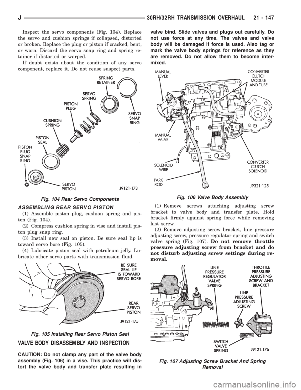
Inspect the servo components (Fig. 104). Replace
the servo and cushion springs if collapsed, distorted
or broken. Replace the plug or piston if cracked, bent,
or worn. Discard the servo snap ring and spring re-
tainer if distorted or warped.
If doubt exists about the condition of any servo
component, replace it. Do not reuse suspect parts.
ASSEMBLING REAR SERVO PISTON
(1) Assemble piston plug, cushion spring and pis-
ton (Fig. 104).
(2) Compress cushion spring in vise and install pis-
ton plug snap ring.
(3) Install new seal on piston. Be sure seal lip is
toward servo bore (Fig. 105).
(4) Lubricate piston seal with petroleum jelly. Lu-
bricate other servo parts with transmission fluid.
VALVE BODY DISASSEMBLY AND INSPECTION
CAUTION: Do not clamp any part of the valve body
assembly (Fig. 106) in a vise. This practice will dis-
tort the valve body and transfer plate resulting invalve bind. Slide valves and plugs out carefully. Do
not use force at any time. The valves and valve
body will be damaged if force is used. Also tag or
mark the valve body springs for reference as they
are removed. Do not allow them to become inter-
mixed.
(1) Remove screws attaching adjusting screw
bracket to valve body and transfer plate. Hold
bracket firmly against spring force while removing
last screw.
(2) Remove adjusting screw bracket, line pressure
adjusting screw, pressure regulator spring and switch
valve spring (Fig. 107).Do not remove throttle
pressure adjusting screw from bracket and do
not disturb adjusting screw settings during re-
moval.
Fig. 104 Rear Servo Components
Fig. 105 Installing Rear Servo Piston Seal
Fig. 106 Valve Body Assembly
Fig. 107 Adjusting Screw Bracket And Spring
Removal
J30RH/32RH TRANSMISSION OVERHAUL 21 - 147
Page 1525 of 2198
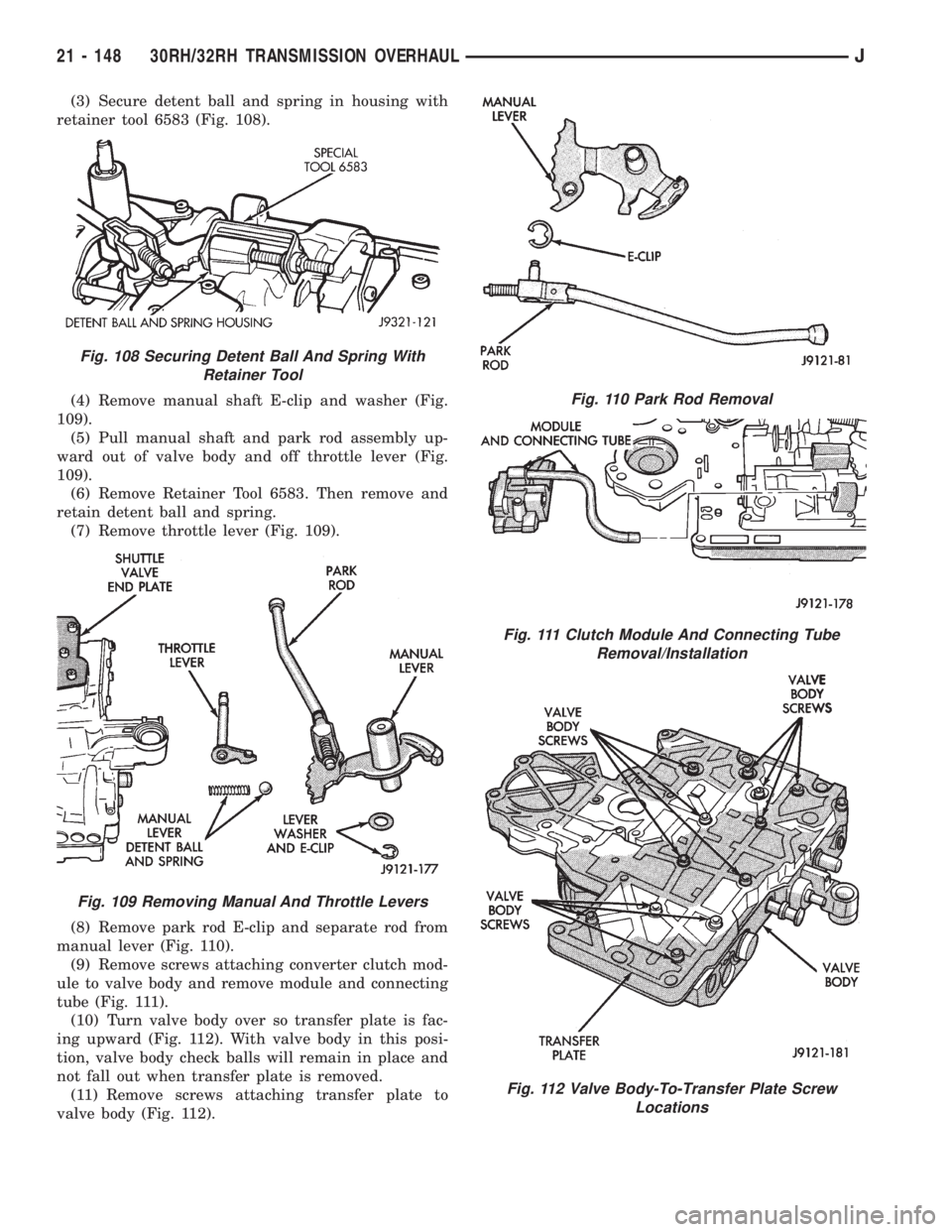
(3) Secure detent ball and spring in housing with
retainer tool 6583 (Fig. 108).
(4) Remove manual shaft E-clip and washer (Fig.
109).
(5) Pull manual shaft and park rod assembly up-
ward out of valve body and off throttle lever (Fig.
109).
(6) Remove Retainer Tool 6583. Then remove and
retain detent ball and spring.
(7) Remove throttle lever (Fig. 109).
(8) Remove park rod E-clip and separate rod from
manual lever (Fig. 110).
(9) Remove screws attaching converter clutch mod-
ule to valve body and remove module and connecting
tube (Fig. 111).
(10) Turn valve body over so transfer plate is fac-
ing upward (Fig. 112). With valve body in this posi-
tion, valve body check balls will remain in place and
not fall out when transfer plate is removed.
(11) Remove screws attaching transfer plate to
valve body (Fig. 112).
Fig. 108 Securing Detent Ball And Spring With
Retainer Tool
Fig. 109 Removing Manual And Throttle Levers
Fig. 110 Park Rod Removal
Fig. 111 Clutch Module And Connecting Tube
Removal/Installation
Fig. 112 Valve Body-To-Transfer Plate Screw
Locations
21 - 148 30RH/32RH TRANSMISSION OVERHAULJ
Page 1526 of 2198
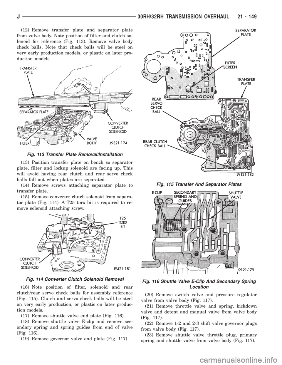
(12) Remove transfer plate and separator plate
from valve body. Note position of filter and clutch so-
lenoid for reference (Fig. 113). Remove valve body
check balls. Note that check balls will be steel on
very early production models, or plastic on later pro-
duction models.
(13) Position transfer plate on bench so separator
plate, filter and lockup solenoid are facing up. This
will avoid having rear clutch and rear servo check
balls fall out when plates are separated.
(14) Remove screws attaching separator plate to
transfer plate.
(15) Remove converter clutch solenoid from separa-
tor plate (Fig. 114). A T25 torx bit is required to re-
move solenoid attaching screw.
(16) Note position of filter, solenoid and rear
clutch/rear servo check balls for assembly reference
(Fig. 115). Clutch and servo check balls will be steel
on very early production, or plastic on later produc-
tion models.
(17) Remove shuttle valve end plate (Fig. 116).
(18) Remove shuttle valve E-clip and remove sec-
ondary spring and spring guides from end of valve
(Fig. 116).
(19) Remove governor valve end plate (Fig. 117).(20) Remove switch valve and pressure regulator
valve from valve body (Fig. 117).
(21) Remove throttle valve and spring, kickdown
valve and detent and manual valve from valve body
(Fig. 117).
(22) Remove 1-2 and 2-3 shift valve governor plugs
from valve body (Fig. 117).
(23) Remove shuttle valve throttle plug, primary
spring and shuttle valve from valve body (Fig. 117).
Fig. 113 Transfer Plate Removal/Installation
Fig. 114 Converter Clutch Solenoid Removal
Fig. 115 Transfer And Separator Plates
Fig. 116 Shuttle Valve E-Clip And Secondary Spring
Location
J30RH/32RH TRANSMISSION OVERHAUL 21 - 149
Page 1527 of 2198
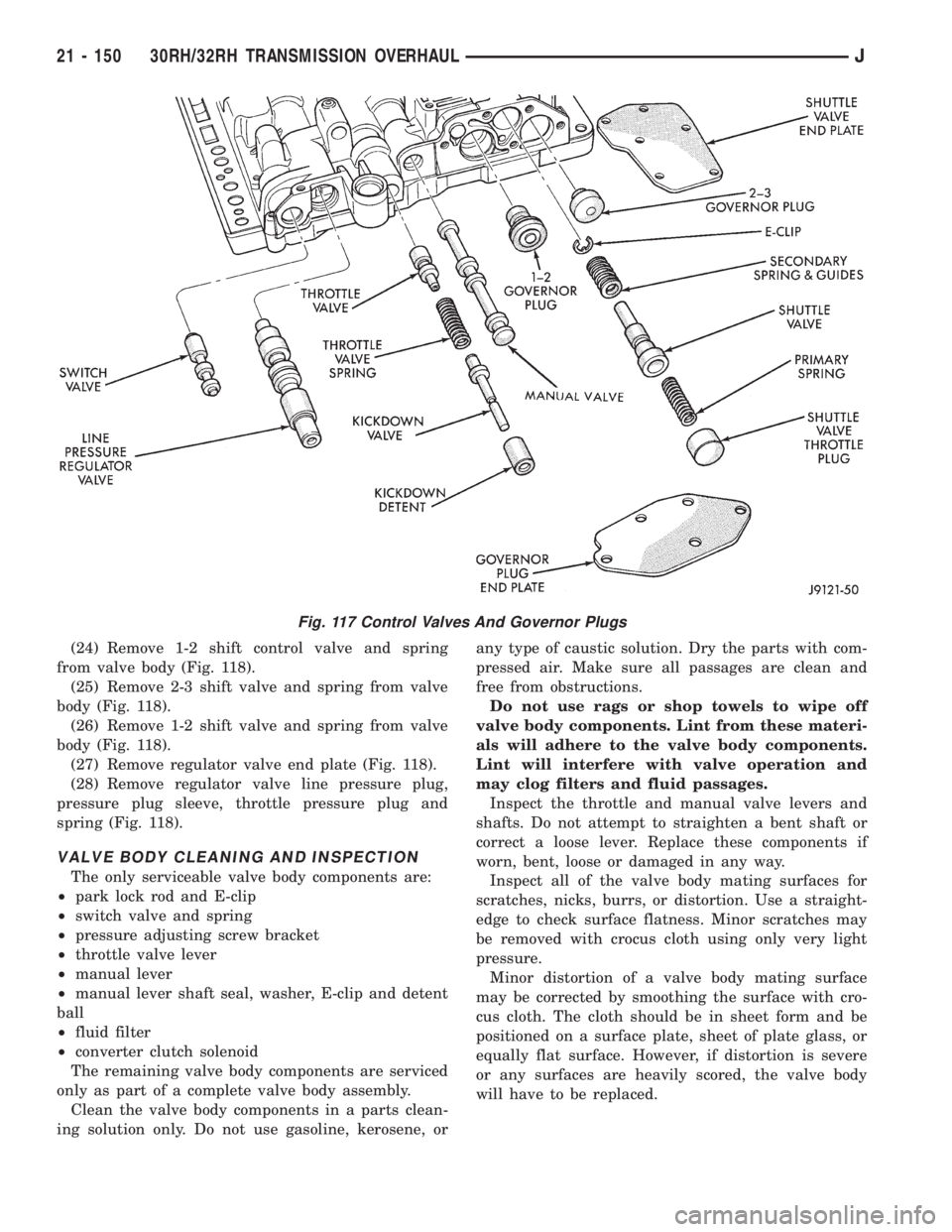
(24) Remove 1-2 shift control valve and spring
from valve body (Fig. 118).
(25) Remove 2-3 shift valve and spring from valve
body (Fig. 118).
(26) Remove 1-2 shift valve and spring from valve
body (Fig. 118).
(27) Remove regulator valve end plate (Fig. 118).
(28) Remove regulator valve line pressure plug,
pressure plug sleeve, throttle pressure plug and
spring (Fig. 118).
VALVE BODY CLEANING AND INSPECTION
The only serviceable valve body components are:
²park lock rod and E-clip
²switch valve and spring
²pressure adjusting screw bracket
²throttle valve lever
²manual lever
²manual lever shaft seal, washer, E-clip and detent
ball
²fluid filter
²converter clutch solenoid
The remaining valve body components are serviced
only as part of a complete valve body assembly.
Clean the valve body components in a parts clean-
ing solution only. Do not use gasoline, kerosene, orany type of caustic solution. Dry the parts with com-
pressed air. Make sure all passages are clean and
free from obstructions.
Do not use rags or shop towels to wipe off
valve body components. Lint from these materi-
als will adhere to the valve body components.
Lint will interfere with valve operation and
may clog filters and fluid passages.
Inspect the throttle and manual valve levers and
shafts. Do not attempt to straighten a bent shaft or
correct a loose lever. Replace these components if
worn, bent, loose or damaged in any way.
Inspect all of the valve body mating surfaces for
scratches, nicks, burrs, or distortion. Use a straight-
edge to check surface flatness. Minor scratches may
be removed with crocus cloth using only very light
pressure.
Minor distortion of a valve body mating surface
may be corrected by smoothing the surface with cro-
cus cloth. The cloth should be in sheet form and be
positioned on a surface plate, sheet of plate glass, or
equally flat surface. However, if distortion is severe
or any surfaces are heavily scored, the valve body
will have to be replaced.
Fig. 117 Control Valves And Governor Plugs
21 - 150 30RH/32RH TRANSMISSION OVERHAULJ
Page 1528 of 2198
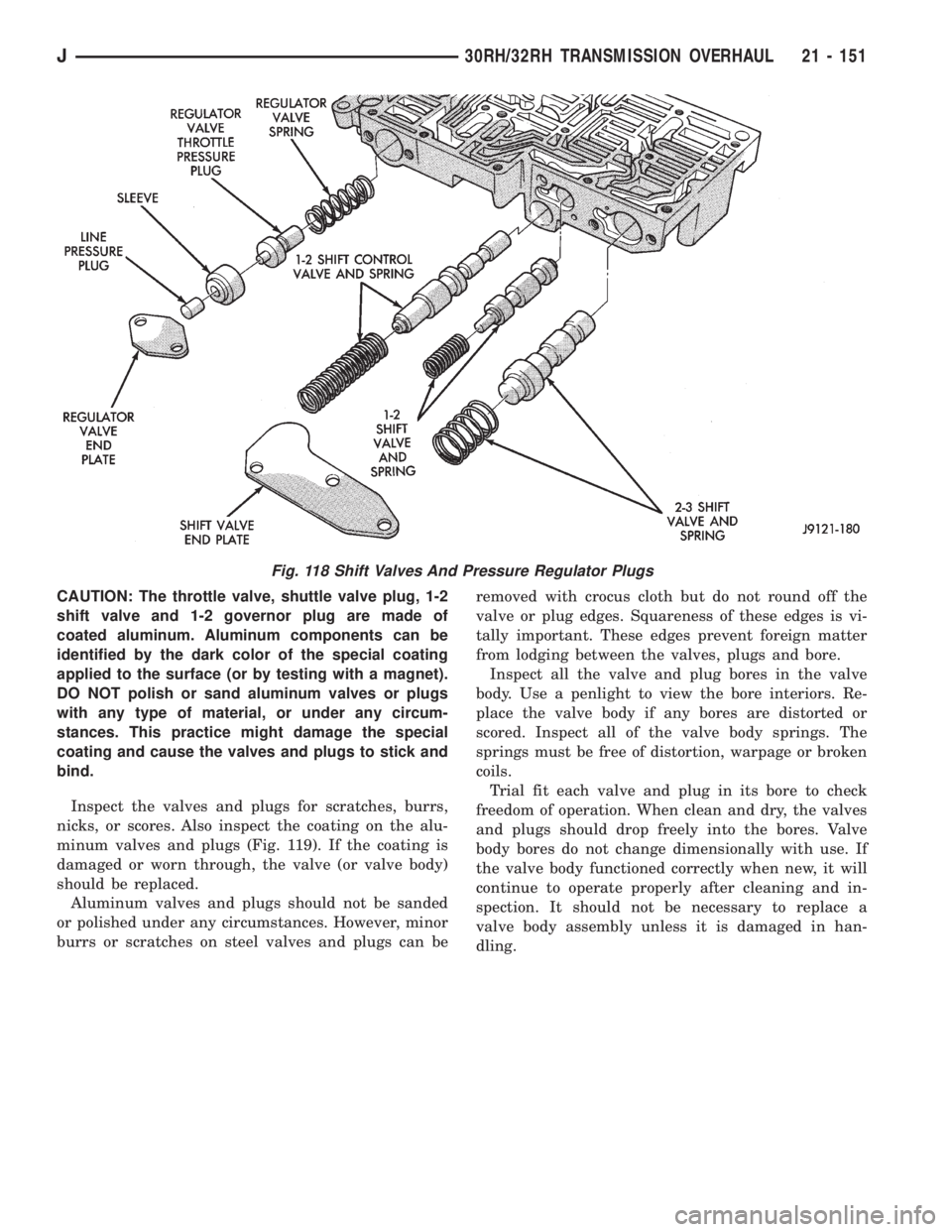
CAUTION: The throttle valve, shuttle valve plug, 1-2
shift valve and 1-2 governor plug are made of
coated aluminum. Aluminum components can be
identified by the dark color of the special coating
applied to the surface (or by testing with a magnet).
DO NOT polish or sand aluminum valves or plugs
with any type of material, or under any circum-
stances. This practice might damage the special
coating and cause the valves and plugs to stick and
bind.
Inspect the valves and plugs for scratches, burrs,
nicks, or scores. Also inspect the coating on the alu-
minum valves and plugs (Fig. 119). If the coating is
damaged or worn through, the valve (or valve body)
should be replaced.
Aluminum valves and plugs should not be sanded
or polished under any circumstances. However, minor
burrs or scratches on steel valves and plugs can beremoved with crocus cloth but do not round off the
valve or plug edges. Squareness of these edges is vi-
tally important. These edges prevent foreign matter
from lodging between the valves, plugs and bore.
Inspect all the valve and plug bores in the valve
body. Use a penlight to view the bore interiors. Re-
place the valve body if any bores are distorted or
scored. Inspect all of the valve body springs. The
springs must be free of distortion, warpage or broken
coils.
Trial fit each valve and plug in its bore to check
freedom of operation. When clean and dry, the valves
and plugs should drop freely into the bores. Valve
body bores do not change dimensionally with use. If
the valve body functioned correctly when new, it will
continue to operate properly after cleaning and in-
spection. It should not be necessary to replace a
valve body assembly unless it is damaged in han-
dling.
Fig. 118 Shift Valves And Pressure Regulator Plugs
J30RH/32RH TRANSMISSION OVERHAUL 21 - 151
Page 1529 of 2198
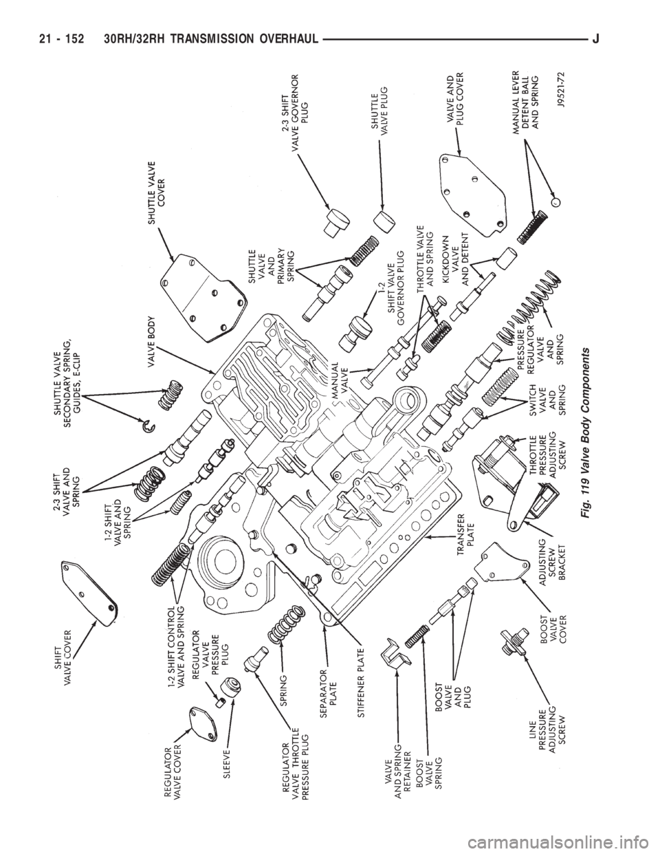
Fig. 119 Valve Body Components
21 - 152 30RH/32RH TRANSMISSION OVERHAULJ
Page 1530 of 2198
VALVE BODY ASSEMBLY AND ADJUSTMENT
CAUTION: Do not force valves or plugs into place
during reassembly. If the valve body bores, valves
and plugs are free of distortion or burrs, the valve
body components should all slide into place easily.
In addition, do not overtighten the transfer plate
and valve body screws during reassembly. Over-
tightening can distort the valve body resulting in
valve sticking, cross leakage and unsatisfactory op-
eration. Tighten valve body screws to recom-
mended torque only.
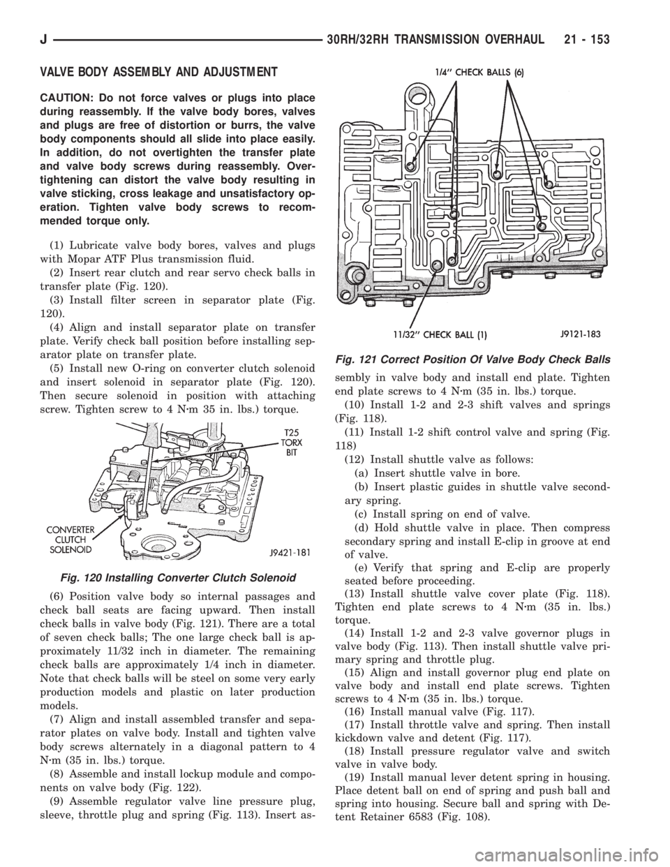
(1) Lubricate valve body bores, valves and plugs
with Mopar ATF Plus transmission fluid.
(2) Insert rear clutch and rear servo check balls in
transfer plate (Fig. 120).
(3) Install filter screen in separator plate (Fig.
120).
(4) Align and install separator plate on transfer
plate. Verify check ball position before installing sep-
arator plate on transfer plate.
(5) Install new O-ring on converter clutch solenoid
and insert solenoid in separator plate (Fig. 120).
Then secure solenoid in position with attaching
screw. Tighten screw to 4 Nzm 35 in. lbs.) torque.
(6) Position valve body so internal passages and
check ball seats are facing upward. Then install
check balls in valve body (Fig. 121). There are a total
of seven check balls; The one large check ball is ap-
proximately 11/32 inch in diameter. The remaining
check balls are approximately 1/4 inch in diameter.
Note that check balls will be steel on some very early
production models and plastic on later production
models.
(7) Align and install assembled transfer and sepa-
rator plates on valve body. Install and tighten valve
body screws alternately in a diagonal pattern to 4
Nzm (35 in. lbs.) torque.
(8) Assemble and install lockup module and compo-
nents on valve body (Fig. 122).
(9) Assemble regulator valve line pressure plug,
sleeve, throttle plug and spring (Fig. 113). Insert as-sembly in valve body and install end plate. Tighten
end plate screws to 4 Nzm (35 in. lbs.) torque.
(10) Install 1-2 and 2-3 shift valves and springs
(Fig. 118).
(11) Install 1-2 shift control valve and spring (Fig.
118)
(12) Install shuttle valve as follows:
(a) Insert shuttle valve in bore.
(b) Insert plastic guides in shuttle valve second-
ary spring.
(c) Install spring on end of valve.
(d) Hold shuttle valve in place. Then compress
secondary spring and install E-clip in groove at end
of valve.
(e) Verify that spring and E-clip are properly
seated before proceeding.
(13) Install shuttle valve cover plate (Fig. 118).
Tighten end plate screws to 4 Nzm (35 in. lbs.)
torque.
(14) Install 1-2 and 2-3 valve governor plugs in
valve body (Fig. 113). Then install shuttle valve pri-
mary spring and throttle plug.
(15) Align and install governor plug end plate on
valve body and install end plate screws. Tighten
screws to 4 Nzm (35 in. lbs.) torque.
(16) Install manual valve (Fig. 117).
(17) Install throttle valve and spring. Then install
kickdown valve and detent (Fig. 117).
(18) Install pressure regulator valve and switch
valve in valve body.
(19) Install manual lever detent spring in housing.
Place detent ball on end of spring and push ball and
spring into housing. Secure ball and spring with De-
tent Retainer 6583 (Fig. 108).
Fig. 120 Installing Converter Clutch Solenoid
Fig. 121 Correct Position Of Valve Body Check Balls
J30RH/32RH TRANSMISSION OVERHAUL 21 - 153