JEEP CHEROKEE 1995 Service Repair Manual
Manufacturer: JEEP, Model Year: 1995, Model line: CHEROKEE, Model: JEEP CHEROKEE 1995Pages: 2198, PDF Size: 82.83 MB
Page 1491 of 2198
(3) If vehicle is equipped withauxiliary cooler,
test cooler flow as described in step (2).
TRANSMISSION COOLER REVERSE FLUSHING
The flushing procedure applies to standard and
auxiliary coolers alike. Although pressure equipment
is preferred, reverse flushing can be performed with
hand operated equipment as follows.
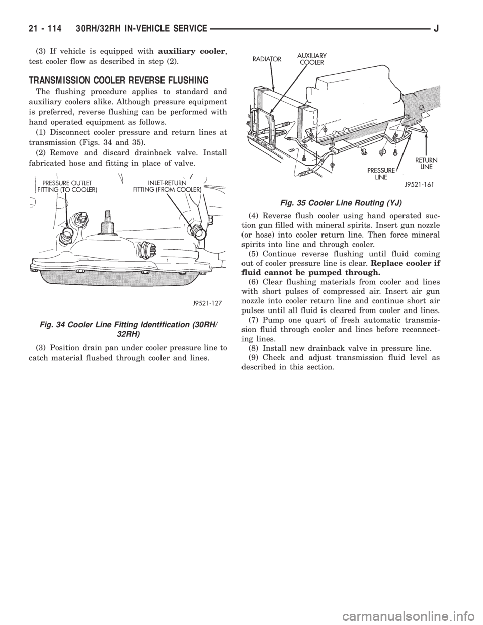
(1) Disconnect cooler pressure and return lines at
transmission (Figs. 34 and 35).
(2) Remove and discard drainback valve. Install
fabricated hose and fitting in place of valve.
(3) Position drain pan under cooler pressure line to
catch material flushed through cooler and lines.(4) Reverse flush cooler using hand operated suc-
tion gun filled with mineral spirits. Insert gun nozzle
(or hose) into cooler return line. Then force mineral
spirits into line and through cooler.
(5) Continue reverse flushing until fluid coming
out of cooler pressure line is clear.Replace cooler if
fluid cannot be pumped through.
(6) Clear flushing materials from cooler and lines
with short pulses of compressed air. Insert air gun
nozzle into cooler return line and continue short air
pulses until all fluid is cleared from cooler and lines.
(7) Pump one quart of fresh automatic transmis-
sion fluid through cooler and lines before reconnect-
ing lines.
(8) Install new drainback valve in pressure line.
(9) Check and adjust transmission fluid level as
described in this section.
Fig. 34 Cooler Line Fitting Identification (30RH/
32RH)
Fig. 35 Cooler Line Routing (YJ)
21 - 114 30RH/32RH IN-VEHICLE SERVICEJ
Page 1492 of 2198
30RH/32RH TRANSMISSION REMOVAL AND INSTALLATION
INDEX
page page
ConverterÐPump SealÐDrive Plate Service.... 116
Transmission and Converter Installation........ 117Transmission and Converter Removal......... 115
TRANSMISSION AND CONVERTER REMOVAL
(1) Remove fan shroud attaching bolts.
(2) Disconnect transmission fill tube at upper
bracket.
(3) Raise vehicle.
(4) Remove inspection cover from converter hous-
ing and remove skid plate for access, if necessary.
(5) Remove transmission fill tube and fill tube O-
ring.
(6) Remove starter motor.
(7) Mark propeller shafts and axle yokes for align-
ment reference.
(8) Disconnect propeller shafts at yokes. Secure
shafts to frame rails with wire.
(9) Disconnect exhaust pipes at exhaust manifolds,
if necessary.
(10) Drain transfer case lubricant, if transfer case
will also be serviced.
(11) Disconnect vehicle speed sensor wires.
(12) Disconnect transfer case shift linkage.
(13) Disconnect gearshift cable/linkage and throttle
valve cable at transmission levers.
(14) Disconnect transfer case vent hose. Then dis-
connect indicator switch wires on XJ, or vacuum
switch harness on YJ.
(15) Remove wire harness from clips on transfer
case.
(16) Remove transfer case attaching nuts and re-
move transfer case. Use transmission jack or helper
to support and remove transfer case.
(17) Disconnect park/neutral position switch wires.
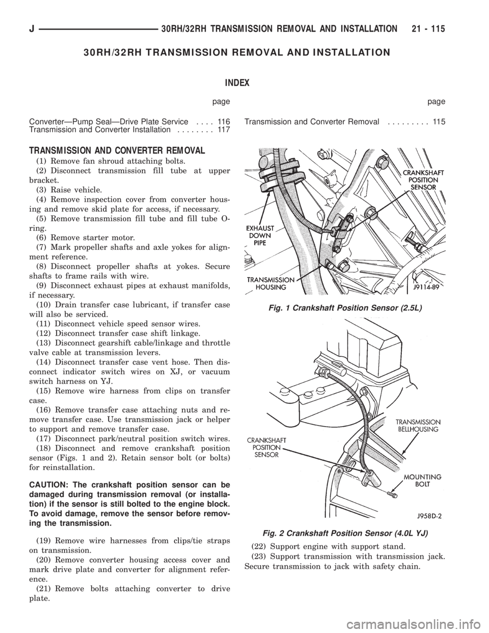
(18) Disconnect and remove crankshaft position
sensor (Figs. 1 and 2). Retain sensor bolt (or bolts)
for reinstallation.
CAUTION: The crankshaft position sensor can be
damaged during transmission removal (or installa-
tion) if the sensor is still bolted to the engine block.
To avoid damage, remove the sensor before remov-
ing the transmission.
(19) Remove wire harnesses from clips/tie straps
on transmission.
(20) Remove converter housing access cover and
mark drive plate and converter for alignment refer-
ence.
(21) Remove bolts attaching converter to drive
plate.(22) Support engine with support stand.
(23) Support transmission with transmission jack.
Secure transmission to jack with safety chain.
Fig. 1 Crankshaft Position Sensor (2.5L)
Fig. 2 Crankshaft Position Sensor (4.0L YJ)
J30RH/32RH TRANSMISSION REMOVAL AND INSTALLATION 21 - 115
Page 1493 of 2198
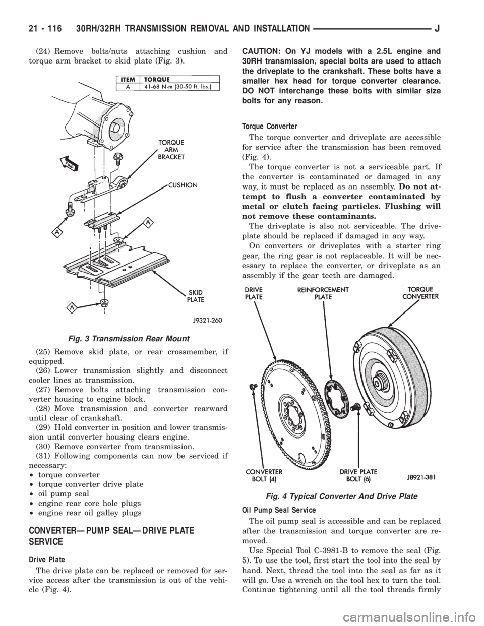
(24) Remove bolts/nuts attaching cushion and
torque arm bracket to skid plate (Fig. 3).
(25) Remove skid plate, or rear crossmember, if
equipped.
(26) Lower transmission slightly and disconnect
cooler lines at transmission.
(27) Remove bolts attaching transmission con-
verter housing to engine block.
(28) Move transmission and converter rearward
until clear of crankshaft.
(29) Hold converter in position and lower transmis-
sion until converter housing clears engine.
(30) Remove converter from transmission.
(31) Following components can now be serviced if
necessary:
²torque converter
²torque converter drive plate
²oil pump seal
²engine rear core hole plugs
²engine rear oil galley plugs
CONVERTERÐPUMP SEALÐDRIVE PLATE
SERVICE
Drive Plate
The drive plate can be replaced or removed for ser-
vice access after the transmission is out of the vehi-
cle (Fig. 4).CAUTION: On YJ models with a 2.5L engine and
30RH transmission, special bolts are used to attach
the driveplate to the crankshaft. These bolts have a
smaller hex head for torque converter clearance.
DO NOT interchange these bolts with similar size
bolts for any reason.
Torque Converter
The torque converter and driveplate are accessible
for service after the transmission has been removed
(Fig. 4).
The torque converter is not a serviceable part. If
the converter is contaminated or damaged in any
way, it must be replaced as an assembly.Do not at-
tempt to flush a converter contaminated by
metal or clutch facing particles. Flushing will
not remove these contaminants.
The driveplate is also not serviceable. The drive-
plate should be replaced if damaged in any way.
On converters or driveplates with a starter ring
gear, the ring gear is not replaceable. It will be nec-
essary to replace the converter, or driveplate as an
assembly if the gear teeth are damaged.
Oil Pump Seal Service
The oil pump seal is accessible and can be replaced
after the transmission and torque converter are re-
moved.
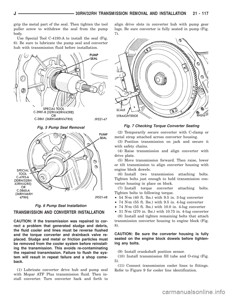
Use Special Tool C-3981-B to remove the seal (Fig.
5). To use the tool, first start the tool into the seal by
hand. Next, thread the tool into the seal as far as it
will go. Use a wrench on the tool hex to turn the tool.
Continue tightening until all the tool threads firmly
Fig. 3 Transmission Rear Mount
Fig. 4 Typical Converter And Drive Plate
21 - 116 30RH/32RH TRANSMISSION REMOVAL AND INSTALLATIONJ
Page 1494 of 2198
grip the metal part of the seal. Then tighten the tool
puller screw to withdraw the seal from the pump
body.
Use Special Tool C-4193-A to install the seal (Fig.
6). Be sure to lubricate the pump seal and converter
hub with transmission fluid before installation.
TRANSMISSION AND CONVERTER INSTALLATION
CAUTION: If the transmission was repaired to cor-
rect a problem that generated sludge and debris,
the fluid cooler and lines must be reverse flushed
and the torque converter and drainback valve re-
placed. Sludge and metal or friction particles must
be removed from the cooler system before reinstall-
ing the transmission. This avoids re-contaminating
the repaired transmission. Failure to flush the sys-
tem will result in repeat failure and a shop come-
back.
(1) Lubricate converter drive hub and pump seal
with Mopar ATF Plus transmission fluid. Then in-
stall converter. Turn converter back and forth toalign drive slots in converter hub with pump gear
lugs. Be sure converter is fully seated in pump (Fig.
7).
(2) Temporarily secure converter with C-clamp or
metal strap attached across converter housing.
(3) Position transmission on jack and secure it
with safety chains.
(4) Raise transmission and align converter with
drive plate.
(5) Move transmission forward. Then raise, lower
or tilt transmission to align converter housing with
engine block dowels.
(6) Install two transmission attaching bolts.
Tighten bolts just enough to hold transmission con-
verter housing in place on block.
(7) Install torque converter attaching bolts.
Tighten bolts to following torque.
²54 Nzm (40 ft. lbs.) with 9.5 in. 3-lug converter
²74 Nzm (55 ft. lbs.) with 9.5 in. 4-lug converter
²74 Nzm (55 ft. lbs.) with 10.0 in. 4-lug converter
²31 Nzm (270 in. lbs.) with 10.75 in. 4-lug converter
(8) Install and tighten remaining bolts that attach
transmission converter housing to engine block (Fig.
8).
CAUTION: Be sure the converter housing is fully
seated on the engine block dowels before tighten-
ing any bolts.
(9) Install crankshaft position sensor.
(10) Install transmission fill tube and O-ring (Fig.
5).
(11) Connect transmission cooler lines to fittings.
Refer to Figure 9 for cooler line identification.
Fig. 5 Pump Seal Removal
Fig. 6 Pump Seal Installation
Fig. 7 Checking Torque Converter Seating
J30RH/32RH TRANSMISSION REMOVAL AND INSTALLATION 21 - 117
Page 1495 of 2198
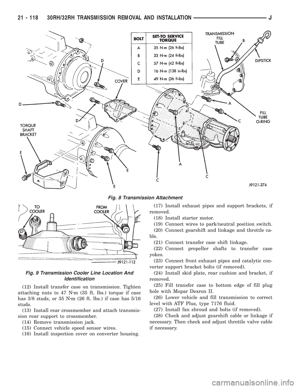
(12) Install transfer case on transmission. Tighten
attaching nuts to 47 Nzm (35 ft. lbs.) torque if case
has 3/8 studs, or 35 Nzm (26 ft. lbs.) if case has 5/16
studs.
(13) Install rear crossmember and attach transmis-
sion rear support to crossmember.
(14) Remove transmission jack.
(15) Connect vehicle speed sensor wires.
(16) Install inspection cover on converter housing.(17) Install exhaust pipes and support brackets, if
removed.
(18) Install starter motor.
(19) Connect wires to park/neutral position switch.
(20) Connect gearshift and linkage and throttle ca-
ble.
(21) Connect transfer case shift linkage.
(22) Connect propeller shafts to transfer case
yokes.
(23) Connect front exhaust pipes and catalytic con-
verter support bracket bolts (if removed).
(24) Install skid plate, rear cushion and bracket, if
removed.
(25) Fill transfer case to bottom edge of fill plug
hole with Mopar Dexron II.
(26) Lower vehicle and fill transmission to correct
level with ATF Plus, type 7176 fluid.
(27) Install fan shroud and bolts (if removed).
(28) Check and adjust gearshift cable or linkage if
necessary. Then check and adjust throttle valve cable
if necessary.
Fig. 8 Transmission Attachment
Fig. 9 Transmission Cooler Line Location And
Identification
21 - 118 30RH/32RH TRANSMISSION REMOVAL AND INSTALLATIONJ
Page 1496 of 2198
30RH/32RH TRANSMISSION OVERHAUL
INDEX
page page
Adapter/Extension Housing Inspection and Park
Lock Component Overhaul................ 127
Front Clutch Overhaul..................... 134
Front Servo and Band Overhaul............. 146
Governor and Park Gear Overhaul........... 127
Oil Pump Overhaul....................... 131
Overhaul Service Information................ 125
Overrunning ClutchÐLow-Reverse DrumÐRear
Support Overhaul....................... 125
Planetary Gear Train Overhaul.............. 141Rear Clutch Overhaul..................... 138
Rear Servo and Band Overhaul.............. 146
Transmission Assembly and Adjustment Procedures. 155
Transmission Assembly Tips................ 155
Transmission Case Cleaning and Inspection.... 125
Transmission Disassembly.................. 119
Valve Body Assembly and Adjustment......... 153
Valve Body Disassembly and Inspection....... 147
TRANSMISSION DISASSEMBLY
(1) Clean transmission exterior with steam gun or
with solvent. Wear eye protection during cleaning
process.
(2) Remove throttle and shift levers from valve
body manual shaft and throttle lever shaft.
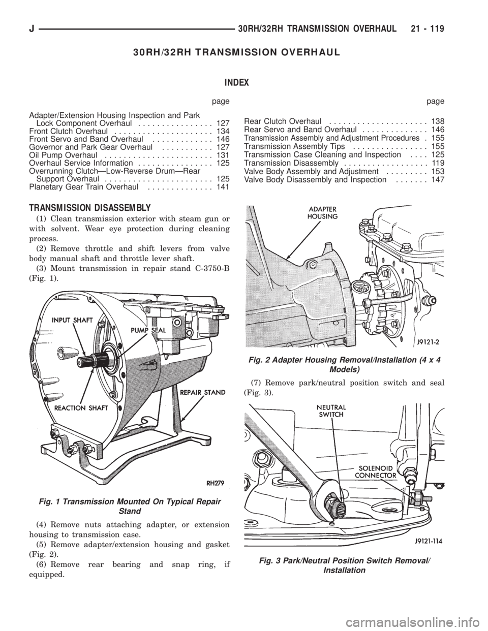
(3) Mount transmission in repair stand C-3750-B
(Fig. 1).
(4) Remove nuts attaching adapter, or extension
housing to transmission case.
(5) Remove adapter/extension housing and gasket
(Fig. 2).
(6) Remove rear bearing and snap ring, if
equipped.(7) Remove park/neutral position switch and seal
(Fig. 3).
Fig. 1 Transmission Mounted On Typical Repair
Stand
Fig. 2 Adapter Housing Removal/Installation (4 x 4
Models)
Fig. 3 Park/Neutral Position Switch Removal/
Installation
J30RH/32RH TRANSMISSION OVERHAUL 21 - 119
Page 1497 of 2198
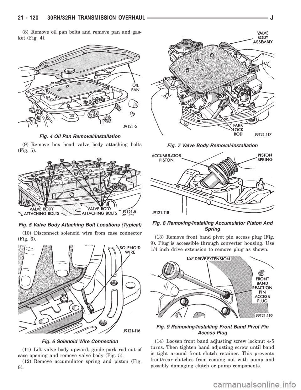
(8) Remove oil pan bolts and remove pan and gas-
ket (Fig. 4).
(9) Remove hex head valve body attaching bolts
(Fig. 5).
(10) Disconnect solenoid wire from case connector
(Fig. 6).
(11) Lift valve body upward, guide park rod out of
case opening and remove valve body (Fig. 5).
(12) Remove accumulator spring and piston (Fig.
8).(13) Remove front band pivot pin access plug (Fig.
9). Plug is accessible through converter housing. Use
1/4 inch drive extension to remove plug as shown.
(14) Loosen front band adjusting screw locknut 4-5
turns. Then tighten band adjusting screw until band
is tight around front clutch retainer. This prevents
front/rear clutches from coming out with pump and
possibly damaging clutch or pump components.
Fig. 4 Oil Pan Removal/Installation
Fig. 5 Valve Body Attaching Bolt Locations (Typical)
Fig. 6 Solenoid Wire Connection
Fig. 7 Valve Body Removal/Installation
Fig. 8 Removing/Installing Accumulator Piston And
Spring
Fig. 9 Removing/Installing Front Band Pivot Pin
Access Plug
21 - 120 30RH/32RH TRANSMISSION OVERHAULJ
Page 1498 of 2198
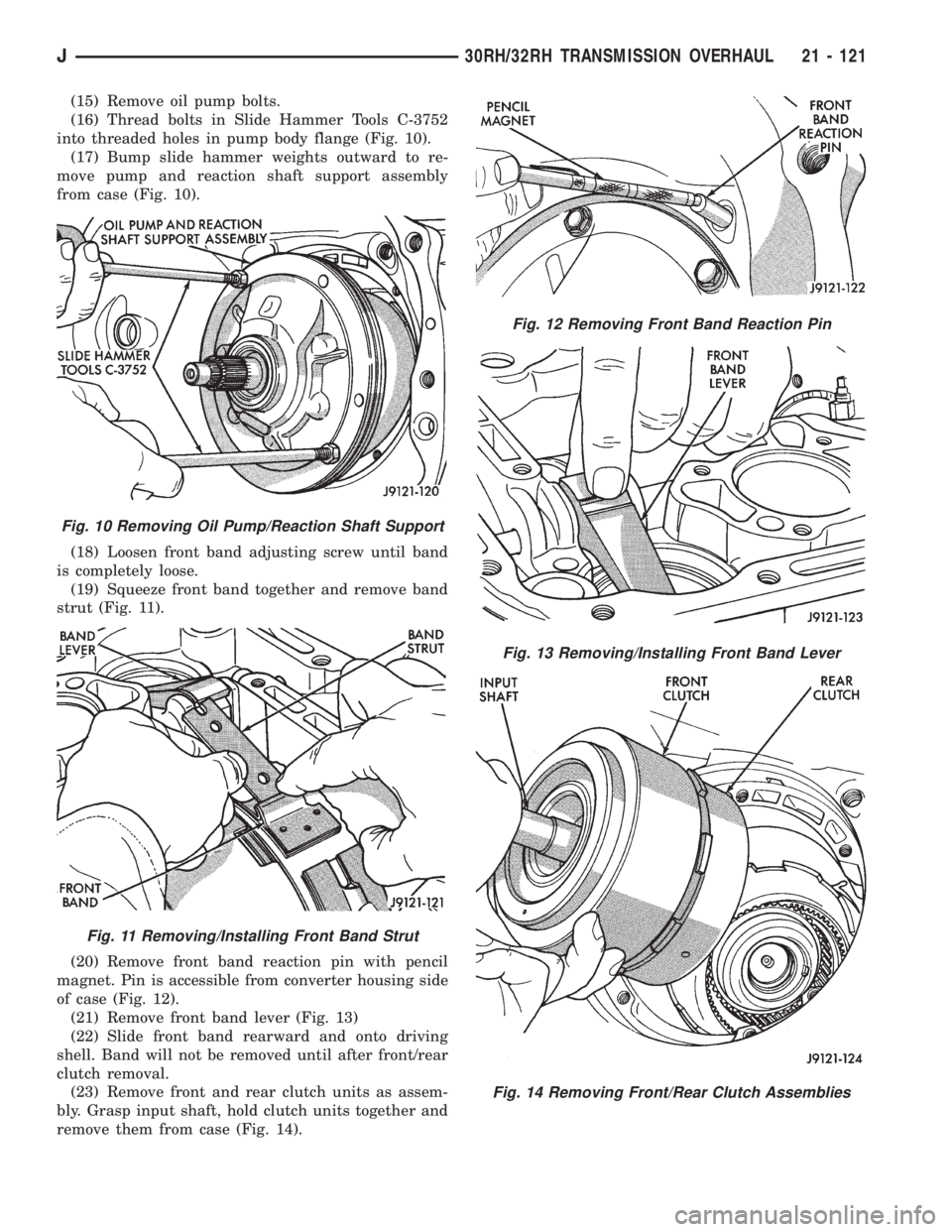
(15) Remove oil pump bolts.
(16) Thread bolts in Slide Hammer Tools C-3752
into threaded holes in pump body flange (Fig. 10).
(17) Bump slide hammer weights outward to re-
move pump and reaction shaft support assembly
from case (Fig. 10).
(18) Loosen front band adjusting screw until band
is completely loose.
(19) Squeeze front band together and remove band
strut (Fig. 11).
(20) Remove front band reaction pin with pencil
magnet. Pin is accessible from converter housing side
of case (Fig. 12).
(21) Remove front band lever (Fig. 13)
(22) Slide front band rearward and onto driving
shell. Band will not be removed until after front/rear
clutch removal.
(23) Remove front and rear clutch units as assem-
bly. Grasp input shaft, hold clutch units together and
remove them from case (Fig. 14).
Fig. 10 Removing Oil Pump/Reaction Shaft Support
Fig. 11 Removing/Installing Front Band Strut
Fig. 12 Removing Front Band Reaction Pin
Fig. 13 Removing/Installing Front Band Lever
Fig. 14 Removing Front/Rear Clutch Assemblies
J30RH/32RH TRANSMISSION OVERHAUL 21 - 121
Page 1499 of 2198
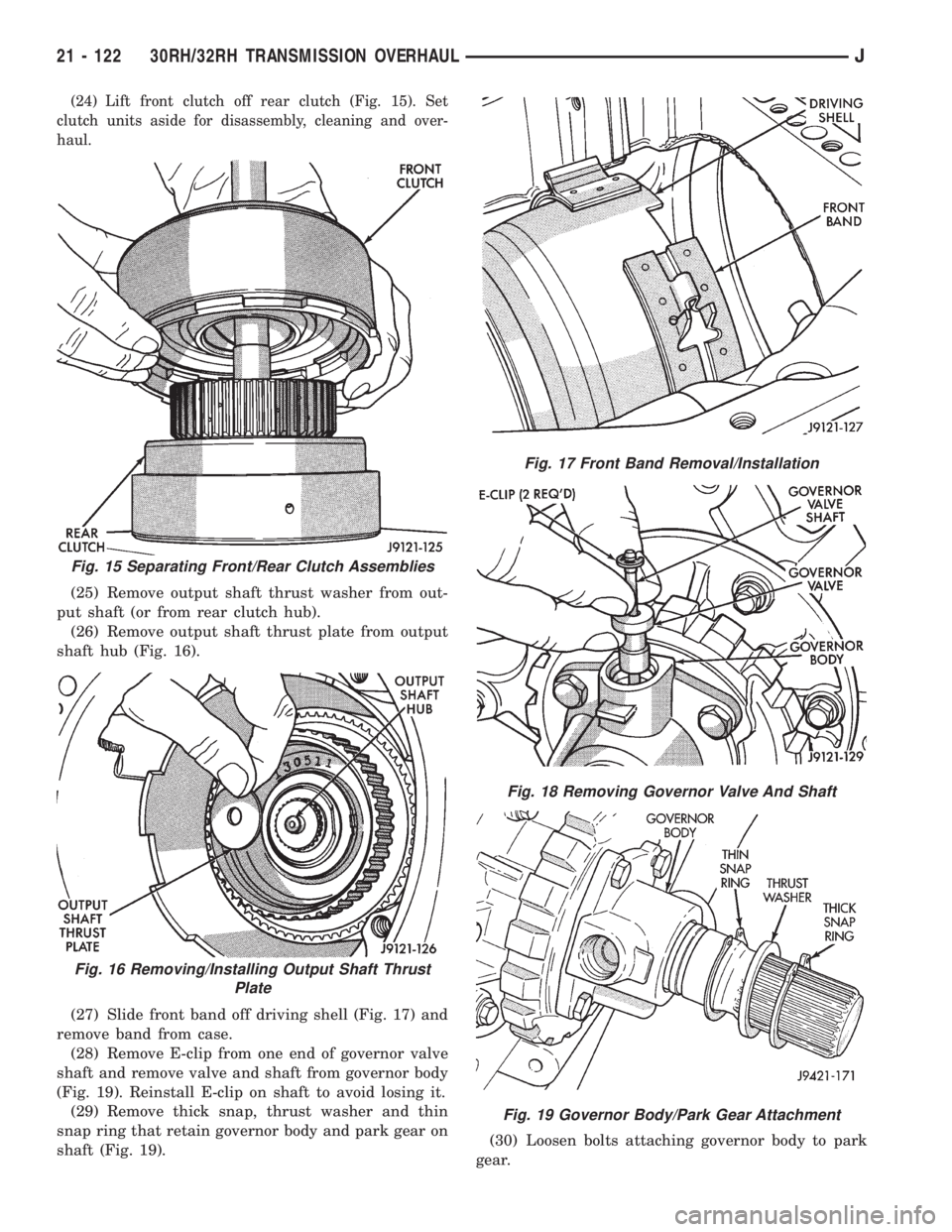
(24) Lift front clutch off rear clutch (Fig. 15). Set
clutch units aside for disassembly, cleaning and over-
haul.
(25) Remove output shaft thrust washer from out-
put shaft (or from rear clutch hub).
(26) Remove output shaft thrust plate from output
shaft hub (Fig. 16).
(27) Slide front band off driving shell (Fig. 17) and
remove band from case.
(28) Remove E-clip from one end of governor valve
shaft and remove valve and shaft from governor body
(Fig. 19). Reinstall E-clip on shaft to avoid losing it.
(29) Remove thick snap, thrust washer and thin
snap ring that retain governor body and park gear on
shaft (Fig. 19).(30) Loosen bolts attaching governor body to park
gear.
Fig. 15 Separating Front/Rear Clutch Assemblies
Fig. 16 Removing/Installing Output Shaft Thrust
Plate
Fig. 17 Front Band Removal/Installation
Fig. 18 Removing Governor Valve And Shaft
Fig. 19 Governor Body/Park Gear Attachment
21 - 122 30RH/32RH TRANSMISSION OVERHAULJ
Page 1500 of 2198
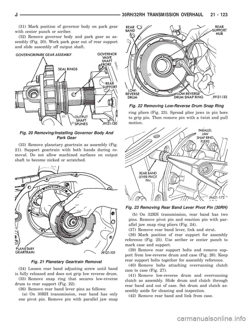
(31) Mark position of governor body on park gear
with center punch or scriber.
(32) Remove governor body and park gear as as-
sembly (Fig. 20). Work park gear out of rear support
and slide assembly off output shaft.
(33) Remove planetary geartrain as assembly (Fig.
21). Support geartrain with both hands during re-
moval. Do not allow machined surfaces on output
shaft to become nicked or scratched.
(34) Loosen rear band adjusting screw until band
is fully released and does not grip low reverse drum.
(35) Remove snap ring that secures low-reverse
drum to rear support (Fig. 22).
(36) Remove rear band lever pins as follows:
(a) On 30RH transmission, rear band has only
one pivot pin. Remove pin with parallel jaw snapring pliers (Fig. 23). Spread plier jaws in pin bore
to grip pin. Then remove pin with a twist and pull
motion.
(b) On 32RH transmission, rear band has two
pins. Remove pivot pin and reaction pin with par-
allel jaw snap ring pliers (Fig. 24).
(37) Remove rear band lever, link and strut.
(38) Mark position of rear support for assembly
reference (Fig. 25). Use scriber or center punch to
mark case and support.
(39) Remove rear support bolts and remove sup-
port from low-reverse drum and case (Fig. 26). Keep
rear support bolts together for assembly reference.
(40) Remove bolts attaching overrunning clutch
cam to case (Fig. 27).
(41) Remove low-reverse drum and overrunning
clutch as assembly. Slide drum and clutch through
rear band and out of case. Set drum and clutch as-
sembly aside for cleaning and inspection.
(42) Remove rear band and link from case.
Fig. 20 Removing/Installing Governor Body And
Park Gear
Fig. 21 Planetary Geartrain Removal
Fig. 22 Removing Low-Reverse Drum Snap Ring
Fig. 23 Removing Rear Band Lever Pivot Pin (30RH)
J30RH/32RH TRANSMISSION OVERHAUL 21 - 123