JEEP CHEROKEE 1995 Service Repair Manual
Manufacturer: JEEP, Model Year: 1995, Model line: CHEROKEE, Model: JEEP CHEROKEE 1995Pages: 2198, PDF Size: 82.83 MB
Page 171 of 2198
MASTER CYLINDER/POWER BRAKE BOOSTER
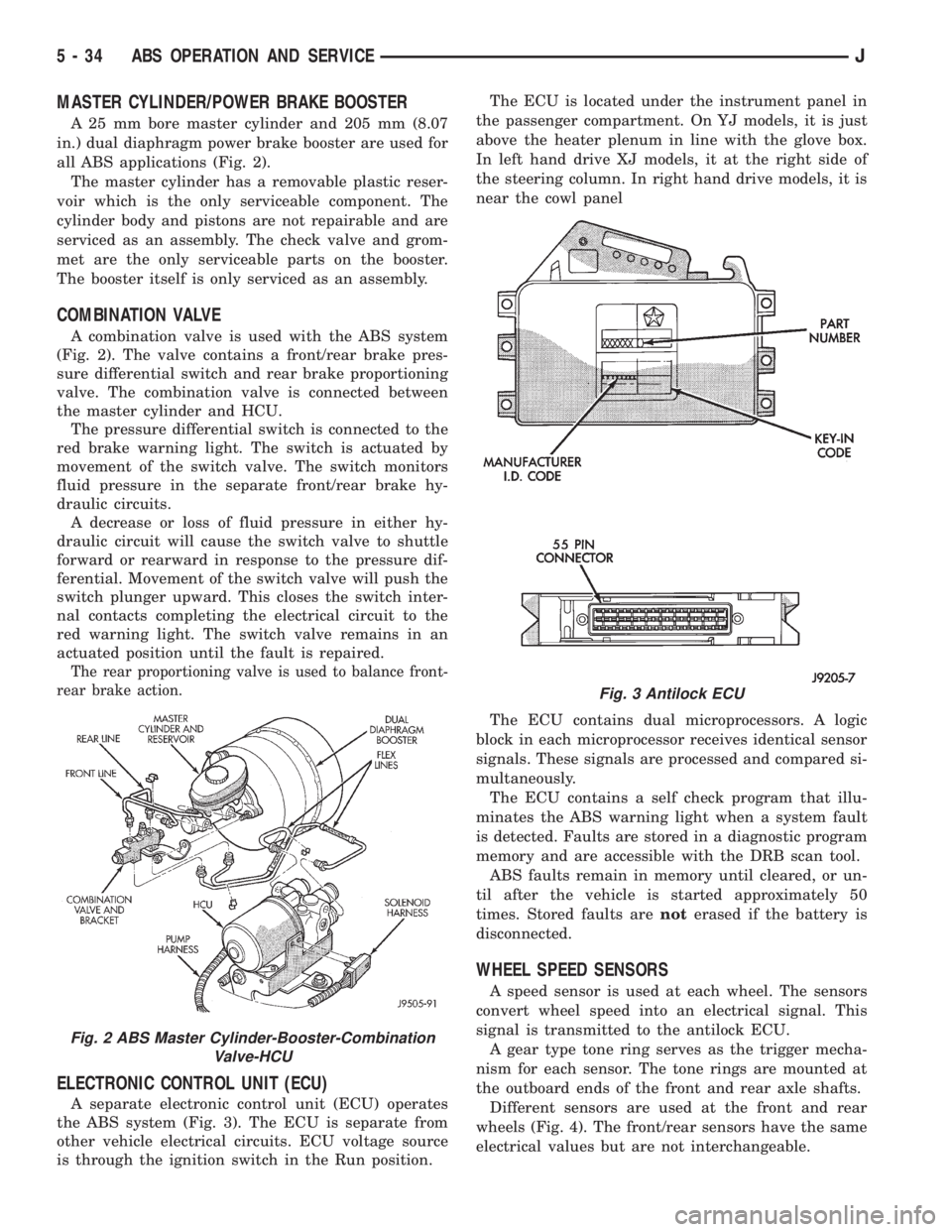
A 25 mm bore master cylinder and 205 mm (8.07
in.) dual diaphragm power brake booster are used for
all ABS applications (Fig. 2).
The master cylinder has a removable plastic reser-
voir which is the only serviceable component. The
cylinder body and pistons are not repairable and are
serviced as an assembly. The check valve and grom-
met are the only serviceable parts on the booster.
The booster itself is only serviced as an assembly.
COMBINATION VALVE
A combination valve is used with the ABS system
(Fig. 2). The valve contains a front/rear brake pres-
sure differential switch and rear brake proportioning
valve. The combination valve is connected between
the master cylinder and HCU.
The pressure differential switch is connected to the
red brake warning light. The switch is actuated by
movement of the switch valve. The switch monitors
fluid pressure in the separate front/rear brake hy-
draulic circuits.
A decrease or loss of fluid pressure in either hy-
draulic circuit will cause the switch valve to shuttle
forward or rearward in response to the pressure dif-
ferential. Movement of the switch valve will push the
switch plunger upward. This closes the switch inter-
nal contacts completing the electrical circuit to the
red warning light. The switch valve remains in an
actuated position until the fault is repaired.
The rear proportioning valve is used to balance front-
rear brake action.
ELECTRONIC CONTROL UNIT (ECU)
A separate electronic control unit (ECU) operates
the ABS system (Fig. 3). The ECU is separate from
other vehicle electrical circuits. ECU voltage source
is through the ignition switch in the Run position.The ECU is located under the instrument panel in
the passenger compartment. On YJ models, it is just
above the heater plenum in line with the glove box.
In left hand drive XJ models, it at the right side of
the steering column. In right hand drive models, it is
near the cowl panel
The ECU contains dual microprocessors. A logic
block in each microprocessor receives identical sensor
signals. These signals are processed and compared si-
multaneously.
The ECU contains a self check program that illu-
minates the ABS warning light when a system fault
is detected. Faults are stored in a diagnostic program
memory and are accessible with the DRB scan tool.
ABS faults remain in memory until cleared, or un-
til after the vehicle is started approximately 50
times. Stored faults arenoterased if the battery is
disconnected.
WHEEL SPEED SENSORS
A speed sensor is used at each wheel. The sensors
convert wheel speed into an electrical signal. This
signal is transmitted to the antilock ECU.
A gear type tone ring serves as the trigger mecha-
nism for each sensor. The tone rings are mounted at
the outboard ends of the front and rear axle shafts.
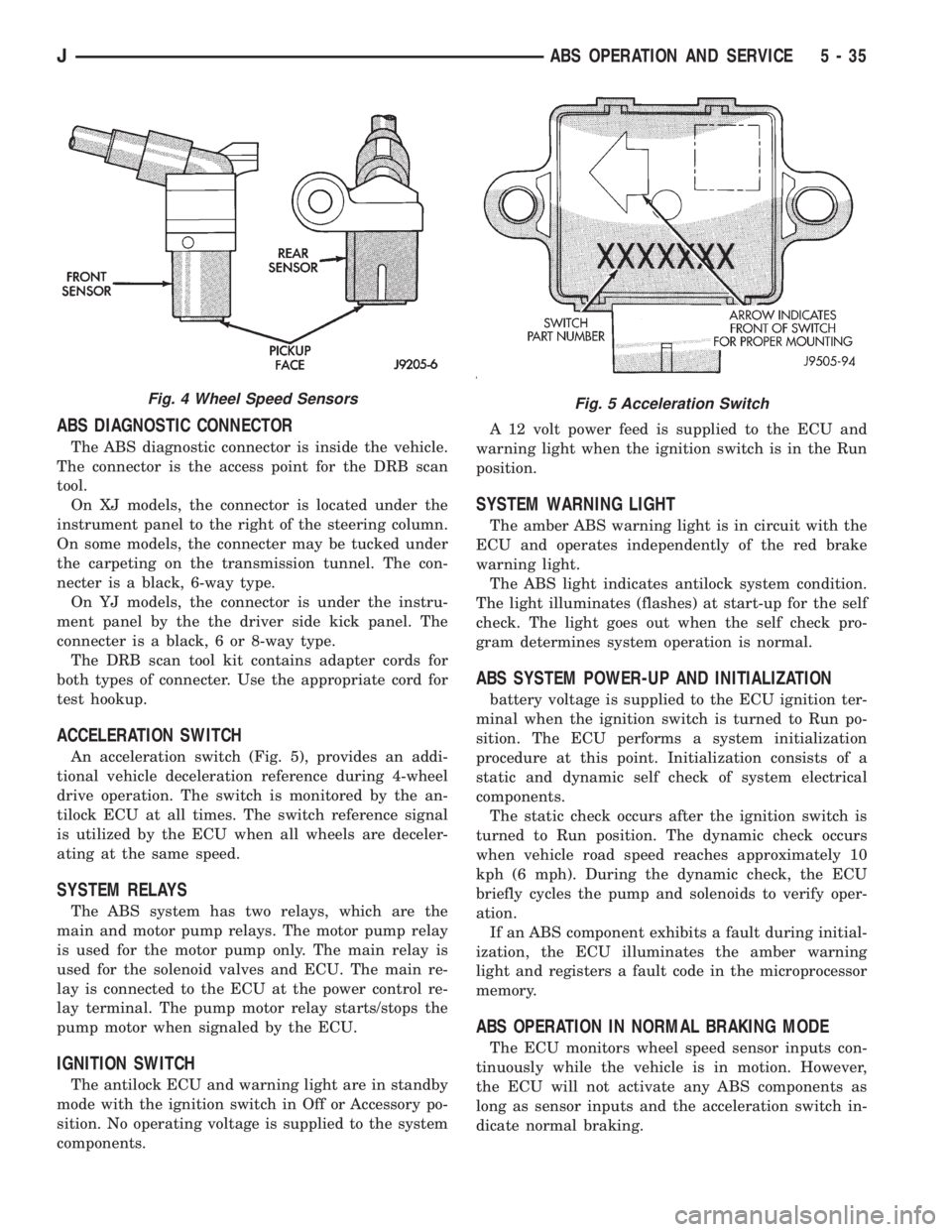
Different sensors are used at the front and rear
wheels (Fig. 4). The front/rear sensors have the same
electrical values but are not interchangeable.
Fig. 2 ABS Master Cylinder-Booster-Combination
Valve-HCU
Fig. 3 Antilock ECU
5 - 34 ABS OPERATION AND SERVICEJ
Page 172 of 2198
ABS DIAGNOSTIC CONNECTOR
The ABS diagnostic connector is inside the vehicle.
The connector is the access point for the DRB scan
tool.
On XJ models, the connector is located under the
instrument panel to the right of the steering column.
On some models, the connecter may be tucked under
the carpeting on the transmission tunnel. The con-
necter is a black, 6-way type.
On YJ models, the connector is under the instru-
ment panel by the the driver side kick panel. The
connecter is a black, 6 or 8-way type.
The DRB scan tool kit contains adapter cords for
both types of connecter. Use the appropriate cord for
test hookup.
ACCELERATION SWITCH
An acceleration switch (Fig. 5), provides an addi-
tional vehicle deceleration reference during 4-wheel
drive operation. The switch is monitored by the an-
tilock ECU at all times. The switch reference signal
is utilized by the ECU when all wheels are deceler-
ating at the same speed.
SYSTEM RELAYS
The ABS system has two relays, which are the
main and motor pump relays. The motor pump relay
is used for the motor pump only. The main relay is
used for the solenoid valves and ECU. The main re-
lay is connected to the ECU at the power control re-
lay terminal. The pump motor relay starts/stops the
pump motor when signaled by the ECU.
IGNITION SWITCH
The antilock ECU and warning light are in standby
mode with the ignition switch in Off or Accessory po-
sition. No operating voltage is supplied to the system
components.A 12 volt power feed is supplied to the ECU and
warning light when the ignition switch is in the Run
position.
SYSTEM WARNING LIGHT
The amber ABS warning light is in circuit with the
ECU and operates independently of the red brake
warning light.
The ABS light indicates antilock system condition.
The light illuminates (flashes) at start-up for the self
check. The light goes out when the self check pro-
gram determines system operation is normal.
ABS SYSTEM POWER-UP AND INITIALIZATION
battery voltage is supplied to the ECU ignition ter-
minal when the ignition switch is turned to Run po-
sition. The ECU performs a system initialization
procedure at this point. Initialization consists of a
static and dynamic self check of system electrical
components.
The static check occurs after the ignition switch is
turned to Run position. The dynamic check occurs
when vehicle road speed reaches approximately 10
kph (6 mph). During the dynamic check, the ECU
briefly cycles the pump and solenoids to verify oper-
ation.
If an ABS component exhibits a fault during initial-
ization, the ECU illuminates the amber warning
light and registers a fault code in the microprocessor
memory.
ABS OPERATION IN NORMAL BRAKING MODE
The ECU monitors wheel speed sensor inputs con-
tinuously while the vehicle is in motion. However,
the ECU will not activate any ABS components as
long as sensor inputs and the acceleration switch in-
dicate normal braking.
Fig. 4 Wheel Speed SensorsFig. 5 Acceleration Switch
JABS OPERATION AND SERVICE 5 - 35
Page 173 of 2198
During normal braking, the master cylinder, power
booster and wheel brake units all function as they
would in a vehicle without ABS. The HCU compo-
nents are not activated.
ABS OPERATION IN ANTILOCK BRAKING MODE
The purpose of the antilock system is to prevent
wheel lockup during periods of high wheel slip. Pre-
venting lockup helps maintain vehicle braking action
and steering control.
The antilock ECU activates the system whenever
sensor signals indicate periods of high wheel slip.
High wheel slip can be described as the point where
wheel rotation begins approaching zero (or lockup)
during braking. Periods of high wheel slip may occur
when brake stops involve high pedal pressure and
rate of deceleration.
The antilock system prevents lockup during high
slip conditions by modulating fluid apply pressure to
the wheel brake units.
Brake fluid apply pressure is modulated according
to wheel speed, degree of slip and rate of decelera-
tion. A sensor at each wheel converts wheel speed
into electrical signals. These signals are transmitted
to the ECU for processing and determination of
wheel slip and deceleration rate.
The ABS system has three fluid pressure control
channels. The front brakes are controlled separately
and the rear brakes in tandem (Fig. 1). A speed sen-
sor input signal indicating a high slip condition acti-
vates the ECU antilock program.
Two solenoid valves are used in each antilock con-
trol channel. The valves are all located within the
HCU valve body and work in pairs to either increase,
hold, or decrease apply pressure as needed in the in-
dividual control channels.
The solenoid valves are not static during antilock
braking. They are cycled continuously to modulate
pressure. Solenoid cycle time in antilock mode can be
measured in milliseconds.
HCU OPERATION
Normal Braking
During normal braking, the HCU solenoid valves
and pump are not activated. The master cylinder and
power booster operate the same as a vehicle without
an ABS brake system.
Antilock Pressure Modulation
Solenoid valve pressure modulation occurs in three
stages which are: pressure increase, pressure hold,
and pressure decrease. The valves are all contained
in the valve body portion of the HCU.
Pressure Decrease
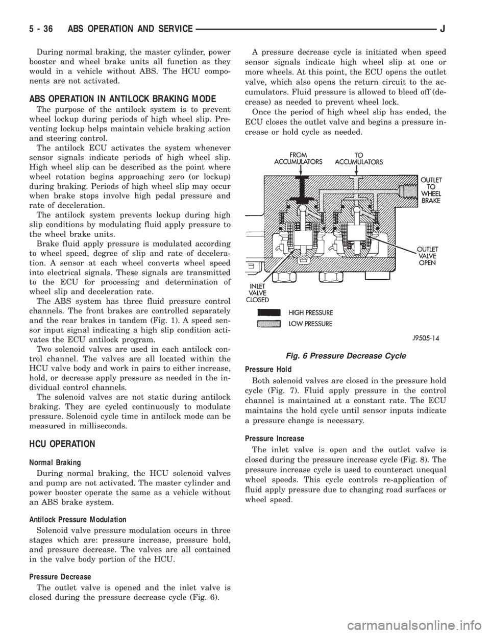
The outlet valve is opened and the inlet valve is
closed during the pressure decrease cycle (Fig. 6).A pressure decrease cycle is initiated when speed
sensor signals indicate high wheel slip at one or
more wheels. At this point, the ECU opens the outlet
valve, which also opens the return circuit to the ac-
cumulators. Fluid pressure is allowed to bleed off (de-
crease) as needed to prevent wheel lock.
Once the period of high wheel slip has ended, the
ECU closes the outlet valve and begins a pressure in-
crease or hold cycle as needed.
Pressure Hold
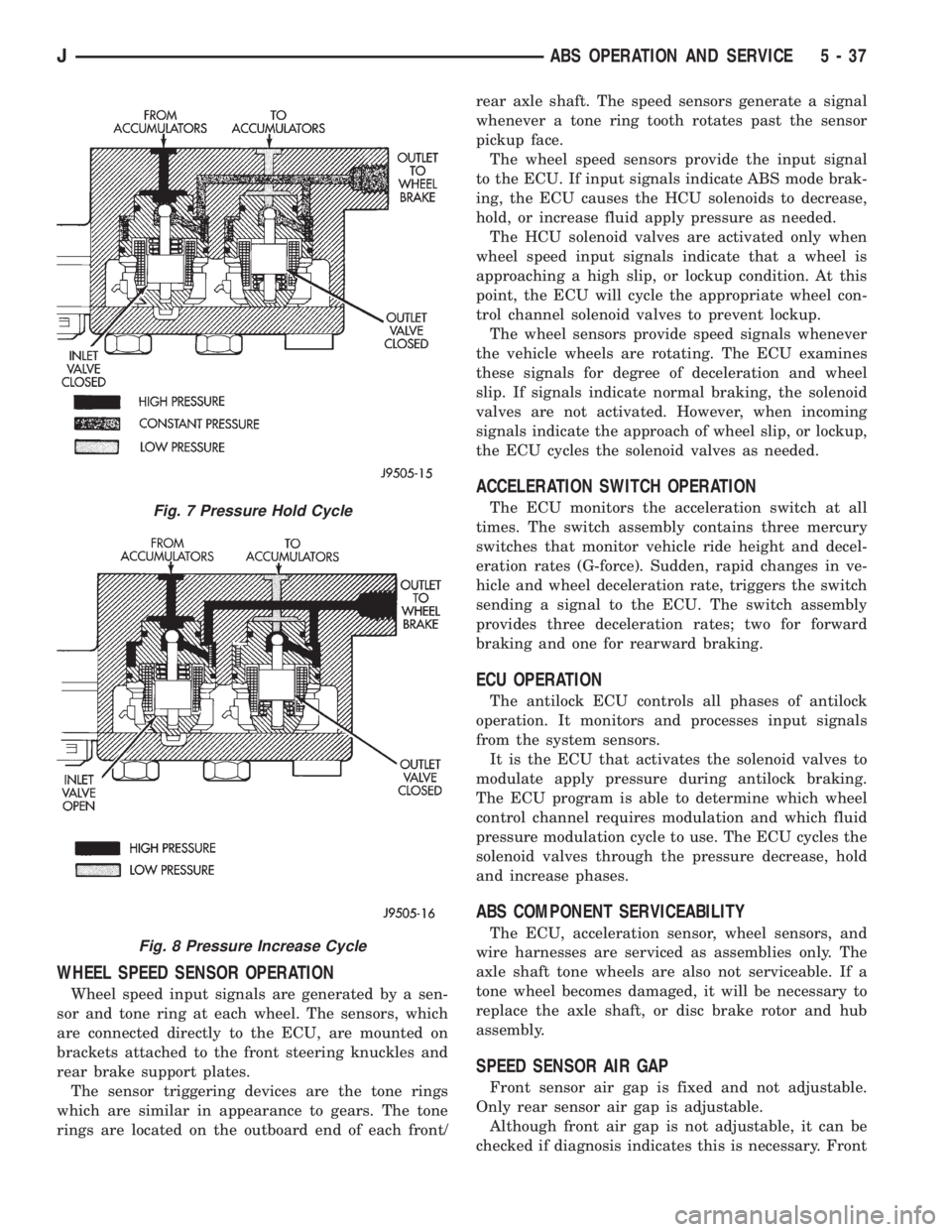
Both solenoid valves are closed in the pressure hold
cycle (Fig. 7). Fluid apply pressure in the control
channel is maintained at a constant rate. The ECU
maintains the hold cycle until sensor inputs indicate
a pressure change is necessary.
Pressure Increase
The inlet valve is open and the outlet valve is
closed during the pressure increase cycle (Fig. 8). The
pressure increase cycle is used to counteract unequal
wheel speeds. This cycle controls re-application of
fluid apply pressure due to changing road surfaces or
wheel speed.
Fig. 6 Pressure Decrease Cycle
5 - 36 ABS OPERATION AND SERVICEJ
Page 174 of 2198
WHEEL SPEED SENSOR OPERATION
Wheel speed input signals are generated by a sen-
sor and tone ring at each wheel. The sensors, which
are connected directly to the ECU, are mounted on
brackets attached to the front steering knuckles and
rear brake support plates.
The sensor triggering devices are the tone rings
which are similar in appearance to gears. The tone
rings are located on the outboard end of each front/rear axle shaft. The speed sensors generate a signal
whenever a tone ring tooth rotates past the sensor
pickup face.
The wheel speed sensors provide the input signal
to the ECU. If input signals indicate ABS mode brak-
ing, the ECU causes the HCU solenoids to decrease,
hold, or increase fluid apply pressure as needed.
The HCU solenoid valves are activated only when
wheel speed input signals indicate that a wheel is
approaching a high slip, or lockup condition. At this
point, the ECU will cycle the appropriate wheel con-
trol channel solenoid valves to prevent lockup.
The wheel sensors provide speed signals whenever
the vehicle wheels are rotating. The ECU examines
these signals for degree of deceleration and wheel
slip. If signals indicate normal braking, the solenoid
valves are not activated. However, when incoming
signals indicate the approach of wheel slip, or lockup,
the ECU cycles the solenoid valves as needed.
ACCELERATION SWITCH OPERATION
The ECU monitors the acceleration switch at all
times. The switch assembly contains three mercury
switches that monitor vehicle ride height and decel-
eration rates (G-force). Sudden, rapid changes in ve-
hicle and wheel deceleration rate, triggers the switch
sending a signal to the ECU. The switch assembly
provides three deceleration rates; two for forward
braking and one for rearward braking.
ECU OPERATION
The antilock ECU controls all phases of antilock
operation. It monitors and processes input signals
from the system sensors.
It is the ECU that activates the solenoid valves to
modulate apply pressure during antilock braking.
The ECU program is able to determine which wheel
control channel requires modulation and which fluid
pressure modulation cycle to use. The ECU cycles the
solenoid valves through the pressure decrease, hold
and increase phases.
ABS COMPONENT SERVICEABILITY
The ECU, acceleration sensor, wheel sensors, and
wire harnesses are serviced as assemblies only. The
axle shaft tone wheels are also not serviceable. If a
tone wheel becomes damaged, it will be necessary to
replace the axle shaft, or disc brake rotor and hub
assembly.
SPEED SENSOR AIR GAP
Front sensor air gap is fixed and not adjustable.
Only rear sensor air gap is adjustable.
Although front air gap is not adjustable, it can be
checked if diagnosis indicates this is necessary. Front
Fig. 7 Pressure Hold Cycle
Fig. 8 Pressure Increase Cycle
JABS OPERATION AND SERVICE 5 - 37
Page 175 of 2198
air gap should be 0.40 to 1.3 mm (0.0157 to 0.051
in.). If gap is incorrect, the sensor is either loose, or
damaged.
A rear sensor air gap adjustment is only needed
when reinstalling an original sensor. Replacement
sensors have an air gap spacer attached to the sensor
pickup face. The spacer establishes correct air gap
when pressed against the tone ring during installa-
tion. As the tone ring rotates, it peels the spacer off
the sensor to create the required air gap. Rear sensor
air gap is 0.92-1.45 mm (0.036-0.057 in.).
Sensor air gap measurement, or adjustment proce-
dures are provided in this section. Refer to the front,
or rear sensor removal and installation procedures as
required.
FRONT WHEEL SENSOR REMOVAL
(1) Raise vehicle and turn wheel outward for easier
access to sensor.
(2) Remove sensor wire from mounting brackets.
(3) Clean sensor and surrounding area with shop
towel before removal.
(4) Remove bolt attaching sensor to steering
knuckle and remove sensor.
(5) remove sensor wire from brackets on body and
steering knuckle.
(6) Unseat sensor wire grommet in wheel house
panel.
(7) In engine compartment, disconnect sensor wire
connector at harness plug. Then remove sensor and
wire.
FRONT WHEEL SENSOR INSTALLATION
(1) Iforiginalsensor will be installed, wipe all
traces of old spacer material off sensor pickup face.
Use a dry shop towel for this purpose.
(2) Apply Mopar Lock N' Seal or Loctite 242 to bolt
that secures sensor in steering knuckle. Use new
sensor bolt if original bolt is worn or damaged.
(3) Position sensor on steering knuckle. Seat sen-
sor locating tab in hole in knuckle and install sensor
attaching bolt finger tight.
(4) Tighten sensor attaching bolt to 14 Nzm (11 ft.
lbs.) torque.
(5) If original sensor has been installed, check sen-
sor air gap. Air gap should be 0.40 to 1.3 mm (0.0157
to 0.051 in.). If gap is incorrect, sensor is either loose,
or damaged.
(6) Secure sensor wire to steering knuckle and
body brackets.
(7) Route sensor wire forward and behind shock
absorber. Then attach sensor wire to spring seat
bracket with grommets on sensor wire.
(8) Route sensor wire to outer sill bracket. Remove
all twists or kinks from wire.
(9) Attach sensor wire to sill bracket with grom-
met. Be sure wire is free of twists and kinks.(10) Verify sensor wire routing. Wire should loop
forward and above sill bracket. Loose end of wire
should be below sill bracket and towards brake hose.
(11) Seat sensor wire grommet in body panel and
clip wire to brake line at grommet location.
(12) Connect sensor wire to harness in engine com-
partment.
REAR WHEEL SENSOR REMOVAL
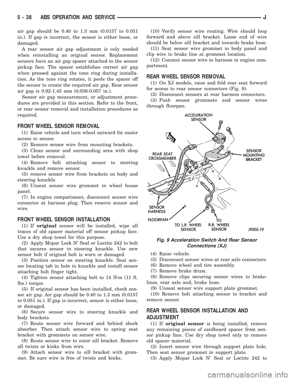
(1) On XJ models, raise and fold rear seat forward
for access to rear sensor connectors (Fig. 9).
(2) Disconnect sensors at rear harness connectors.
(3) Push sensor grommets and sensor wires
through floorpan.
(4) Raise vehicle.
(5) Disconnect sensor wires at rear axle connectors.
(6) Remove wheel and tire assembly.
(7) Remove brake drum.
(8) Remove clips securing sensor wires to brake-
lines, rear axle and, brake hose.
(9) Unseat sensor wire support plate grommet.
(10) Remove bolt attaching sensor to bracket and
remove sensor.
REAR WHEEL SENSOR INSTALLATION AND
ADJUSTMENT
(1) Iforiginal sensoris being installed, remove
any remaining pieces of cardboard spacer from sen-
sor pickup face. Use dry shop towel only to remove
old spacer material.
(2) Insert sensor wire through support plate hole.
Then seat sensor grommet in support plate.
(3) Apply Mopar Lock N' Seal or Loctite 242 to
Fig. 9 Acceleration Switch And Rear Sensor
Connections (XJ)
5 - 38 ABS OPERATION AND SERVICEJ
Page 176 of 2198
original sensor bolt. Use new bolt if original is worn
or damaged.
(4) Install sensor bolt finger tight only at this time.
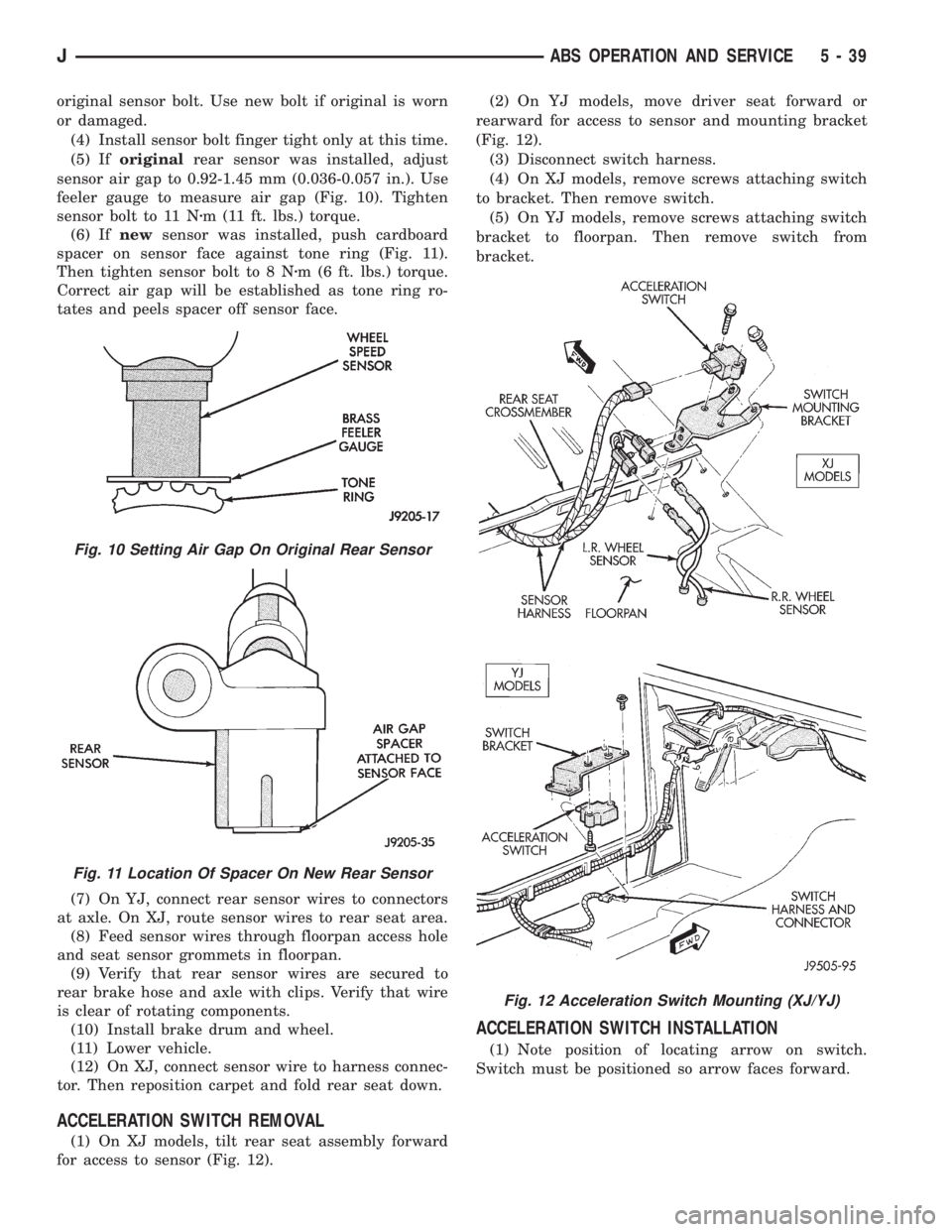
(5) Iforiginalrear sensor was installed, adjust
sensor air gap to 0.92-1.45 mm (0.036-0.057 in.). Use
feeler gauge to measure air gap (Fig. 10). Tighten
sensor bolt to 11 Nzm (11 ft. lbs.) torque.
(6) Ifnewsensor was installed, push cardboard
spacer on sensor face against tone ring (Fig. 11).
Then tighten sensor bolt to 8 Nzm (6 ft. lbs.) torque.
Correct air gap will be established as tone ring ro-
tates and peels spacer off sensor face.
(7) On YJ, connect rear sensor wires to connectors
at axle. On XJ, route sensor wires to rear seat area.
(8) Feed sensor wires through floorpan access hole
and seat sensor grommets in floorpan.
(9) Verify that rear sensor wires are secured to
rear brake hose and axle with clips. Verify that wire
is clear of rotating components.
(10) Install brake drum and wheel.
(11) Lower vehicle.
(12) On XJ, connect sensor wire to harness connec-
tor. Then reposition carpet and fold rear seat down.
ACCELERATION SWITCH REMOVAL
(1) On XJ models, tilt rear seat assembly forward
for access to sensor (Fig. 12).(2) On YJ models, move driver seat forward or
rearward for access to sensor and mounting bracket
(Fig. 12).
(3) Disconnect switch harness.
(4) On XJ models, remove screws attaching switch
to bracket. Then remove switch.
(5) On YJ models, remove screws attaching switch
bracket to floorpan. Then remove switch from
bracket.
ACCELERATION SWITCH INSTALLATION
(1) Note position of locating arrow on switch.
Switch must be positioned so arrow faces forward.
Fig. 10 Setting Air Gap On Original Rear Sensor
Fig. 11 Location Of Spacer On New Rear Sensor
Fig. 12 Acceleration Switch Mounting (XJ/YJ)
JABS OPERATION AND SERVICE 5 - 39
Page 177 of 2198
CAUTION: The mercury switch (inside the accelera-
tion switch), will not function properly if the switch
is mispositioned. Verify that the switch locating ar-
row is pointing to the front of the vehicle.
(2) Position switch in mounting bracket.
(3) Install and tighten switch attaching screws to
2-4 Nzm (17-32 in. lbs.) torque.
(4) Connect harness to switch. Be sure harness
connecter is firmly seated.
(5) Move seat back to normal position.
ECU REMOVAL (XJ MODELS)
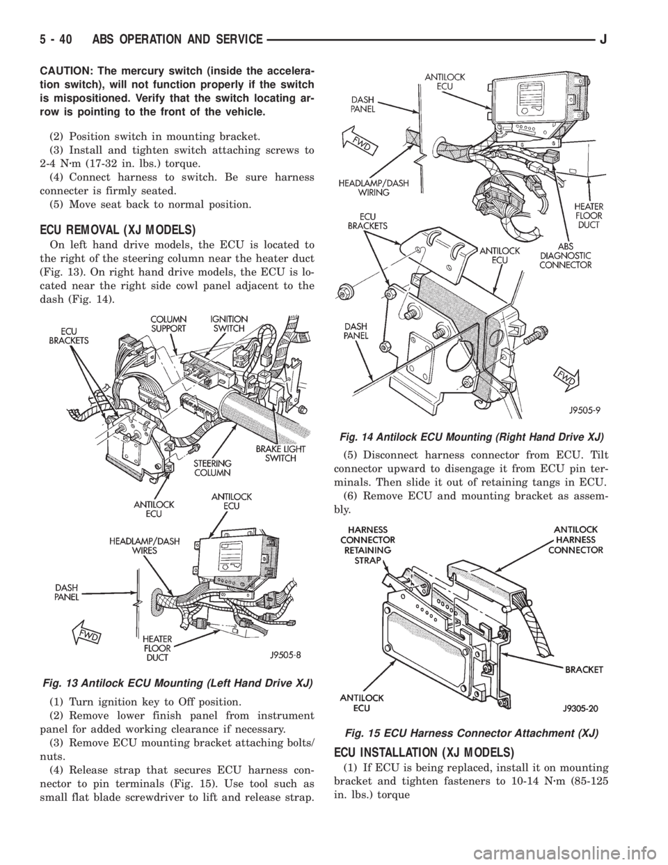
On left hand drive models, the ECU is located to
the right of the steering column near the heater duct
(Fig. 13). On right hand drive models, the ECU is lo-
cated near the right side cowl panel adjacent to the
dash (Fig. 14).
(1) Turn ignition key to Off position.
(2) Remove lower finish panel from instrument
panel for added working clearance if necessary.
(3) Remove ECU mounting bracket attaching bolts/
nuts.
(4) Release strap that secures ECU harness con-
nector to pin terminals (Fig. 15). Use tool such as
small flat blade screwdriver to lift and release strap.(5) Disconnect harness connector from ECU. Tilt
connector upward to disengage it from ECU pin ter-
minals. Then slide it out of retaining tangs in ECU.
(6) Remove ECU and mounting bracket as assem-
bly.
ECU INSTALLATION (XJ MODELS)
(1) If ECU is being replaced, install it on mounting
bracket and tighten fasteners to 10-14 Nzm (85-125
in. lbs.) torque
Fig. 13 Antilock ECU Mounting (Left Hand Drive XJ)
Fig. 14 Antilock ECU Mounting (Right Hand Drive XJ)
Fig. 15 ECU Harness Connector Attachment (XJ)
5 - 40 ABS OPERATION AND SERVICEJ
Page 178 of 2198
(2) Align and attach harness connector to ECU.
Slide connector into engagement with tangs on ECU.
Then tilt connector downward and into engagement
with ECU pin terminals. Exercise care as pin termi-
nals can be damaged if connector is forced into place.
(3) Connect harness to security alarm module, if
equipped.
(4) Position ECU bracket under instrument panel.
(5) Install and tighten ECU mounting bracket
bolts/nuts to 8-14 Nzm (75- 125 in. lbs.) torque.
(6) Install trim panel on instrument panel, if re-
moved.
ECU REMOVAL/INSTALLATION (YJ MODELS)
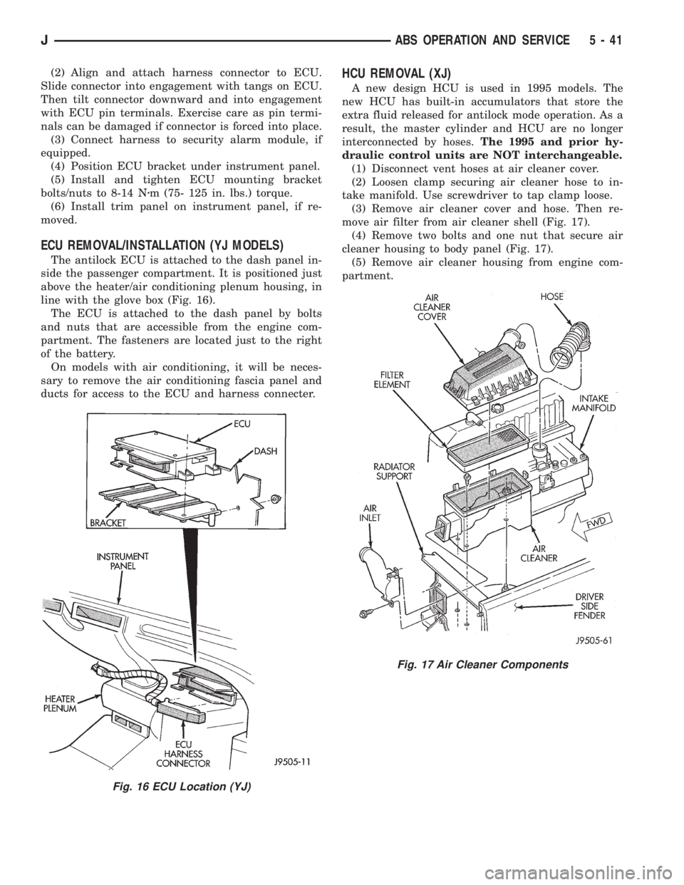
The antilock ECU is attached to the dash panel in-
side the passenger compartment. It is positioned just
above the heater/air conditioning plenum housing, in
line with the glove box (Fig. 16).
The ECU is attached to the dash panel by bolts
and nuts that are accessible from the engine com-
partment. The fasteners are located just to the right
of the battery.
On models with air conditioning, it will be neces-
sary to remove the air conditioning fascia panel and
ducts for access to the ECU and harness connecter.
HCU REMOVAL (XJ)
A new design HCU is used in 1995 models. The
new HCU has built-in accumulators that store the
extra fluid released for antilock mode operation. As a
result, the master cylinder and HCU are no longer
interconnected by hoses.The 1995 and prior hy-
draulic control units are NOT interchangeable.
(1) Disconnect vent hoses at air cleaner cover.
(2) Loosen clamp securing air cleaner hose to in-
take manifold. Use screwdriver to tap clamp loose.
(3) Remove air cleaner cover and hose. Then re-
move air filter from air cleaner shell (Fig. 17).
(4) Remove two bolts and one nut that secure air
cleaner housing to body panel (Fig. 17).
(5) Remove air cleaner housing from engine com-
partment.
Fig. 16 ECU Location (YJ)
Fig. 17 Air Cleaner Components
JABS OPERATION AND SERVICE 5 - 41
Page 179 of 2198
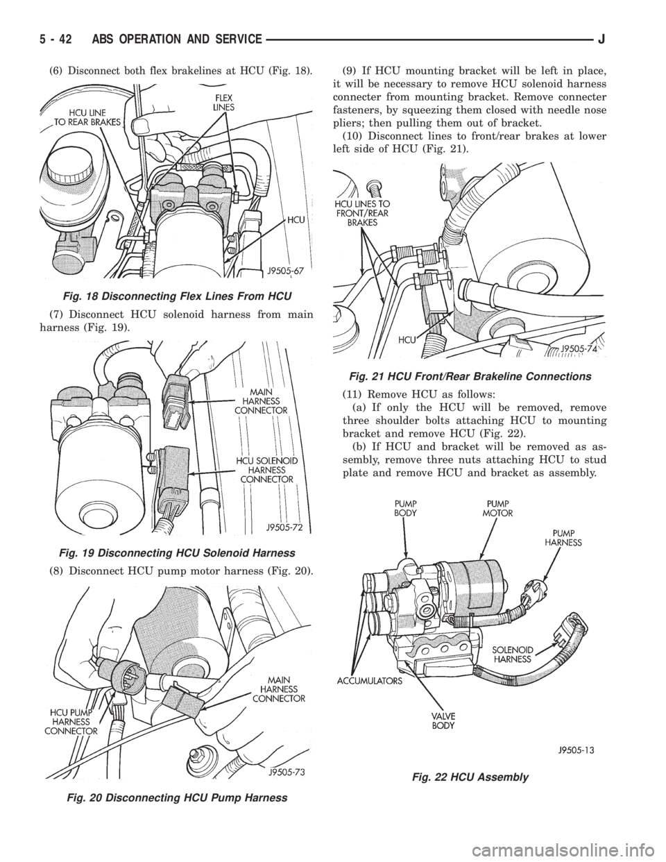
(6) Disconnect both flex brakelines at HCU (Fig. 18).
(7) Disconnect HCU solenoid harness from main
harness (Fig. 19).
(8) Disconnect HCU pump motor harness (Fig. 20).(9) If HCU mounting bracket will be left in place,
it will be necessary to remove HCU solenoid harness
connecter from mounting bracket. Remove connecter
fasteners, by squeezing them closed with needle nose
pliers; then pulling them out of bracket.
(10) Disconnect lines to front/rear brakes at lower
left side of HCU (Fig. 21).
(11) Remove HCU as follows:
(a) If only the HCU will be removed, remove
three shoulder bolts attaching HCU to mounting
bracket and remove HCU (Fig. 22).
(b) If HCU and bracket will be removed as as-
sembly, remove three nuts attaching HCU to stud
plate and remove HCU and bracket as assembly.
Fig. 18 Disconnecting Flex Lines From HCU
Fig. 19 Disconnecting HCU Solenoid Harness
Fig. 20 Disconnecting HCU Pump Harness
Fig. 21 HCU Front/Rear Brakeline Connections
Fig. 22 HCU Assembly
5 - 42 ABS OPERATION AND SERVICEJ
Page 180 of 2198
HCU INSTALLATION (XJ)
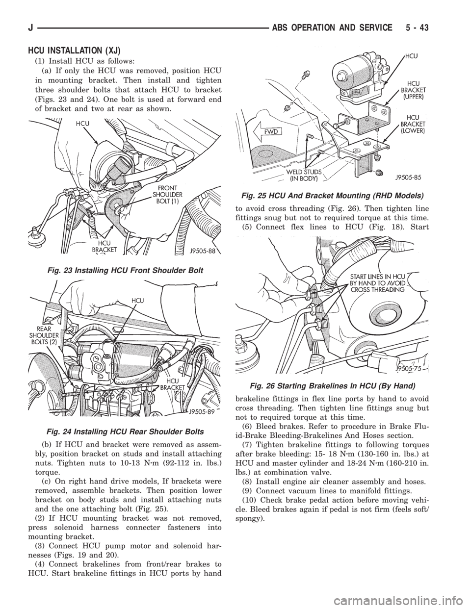
(1) Install HCU as follows:
(a) If only the HCU was removed, position HCU
in mounting bracket. Then install and tighten
three shoulder bolts that attach HCU to bracket
(Figs. 23 and 24). One bolt is used at forward end
of bracket and two at rear as shown.
(b) If HCU and bracket were removed as assem-
bly, position bracket on studs and install attaching
nuts. Tighten nuts to 10-13 Nzm (92-112 in. lbs.)
torque.
(c) On right hand drive models, If brackets were
removed, assemble brackets. Then position lower
bracket on body studs and install attaching nuts
and the one attaching bolt (Fig. 25).
(2) If HCU mounting bracket was not removed,
press solenoid harness connecter fasteners into
mounting bracket.
(3) Connect HCU pump motor and solenoid har-
nesses (Figs. 19 and 20).
(4) Connect brakelines from front/rear brakes to
HCU. Start brakeline fittings in HCU ports by handto avoid cross threading (Fig. 26). Then tighten line
fittings snug but not to required torque at this time.
(5) Connect flex lines to HCU (Fig. 18). Start
brakeline fittings in flex line ports by hand to avoid
cross threading. Then tighten line fittings snug but
not to required torque at this time.
(6) Bleed brakes. Refer to procedure in Brake Flu-
id-Brake Bleeding-Brakelines And Hoses section.
(7) Tighten brakeline fittings to following torques
after brake bleeding: 15- 18 Nzm (130-160 in. lbs.) at
HCU and master cylinder and 18-24 Nzm (160-210 in.
lbs.) at combination valve.
(8) Install engine air cleaner assembly and hoses.
(9) Connect vacuum lines to manifold fittings.
(10) Check brake pedal action before moving vehi-
cle. Bleed brakes again if pedal is not firm (feels soft/
spongy).
Fig. 23 Installing HCU Front Shoulder Bolt
Fig. 24 Installing HCU Rear Shoulder Bolts
Fig. 25 HCU And Bracket Mounting (RHD Models)
Fig. 26 Starting Brakelines In HCU (By Hand)
JABS OPERATION AND SERVICE 5 - 43