JEEP CHEROKEE 1995 Service Repair Manual
Manufacturer: JEEP, Model Year: 1995, Model line: CHEROKEE, Model: JEEP CHEROKEE 1995Pages: 2198, PDF Size: 82.83 MB
Page 351 of 2198
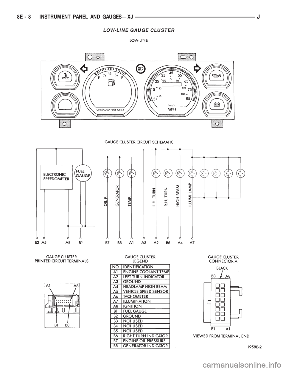
LOW-LINE GAUGE CLUSTER
8E - 8 INSTRUMENT PANEL AND GAUGESÐXJJ
Page 352 of 2198
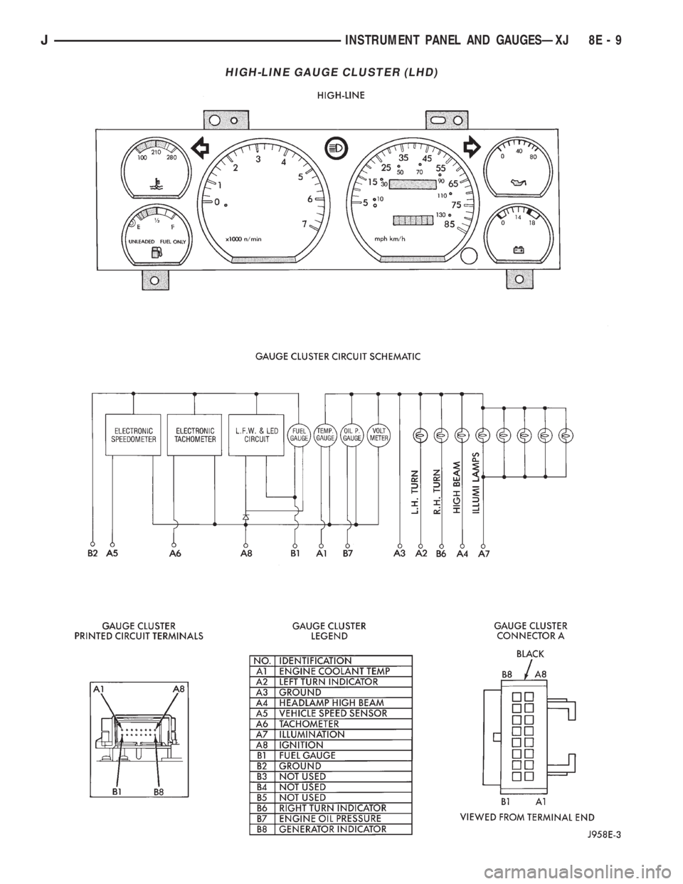
HIGH-LINE GAUGE CLUSTER (LHD)
JINSTRUMENT PANEL AND GAUGESÐXJ 8E - 9
Page 353 of 2198
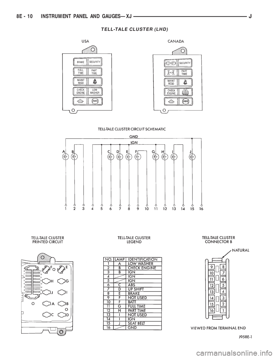
TELL-TALE CLUSTER (LHD)
8E - 10 INSTRUMENT PANEL AND GAUGESÐXJJ
Page 354 of 2198
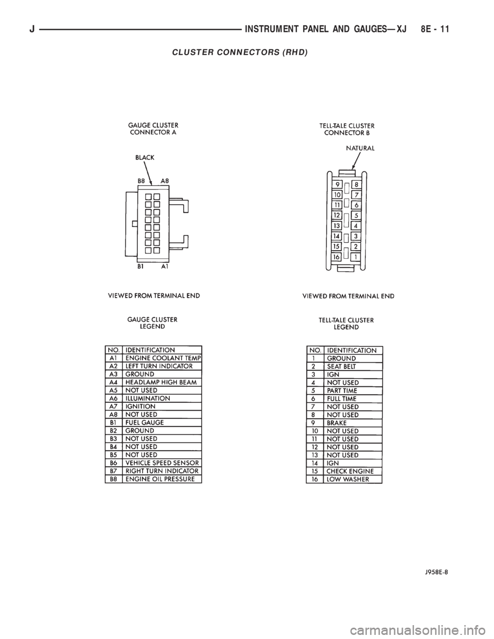
CLUSTER CONNECTORS (RHD)
JINSTRUMENT PANEL AND GAUGESÐXJ 8E - 11
Page 355 of 2198
INDICATOR LAMPS
If an individual indicator lamp is inoperative, see
the diagnostic procedure under the heading for that
lamp. If more than one indicator lamp or a combina-
tion of lamps and gauges in the gauge area of the in-
strument cluster is inoperative, see Gauges in this
section for diagnosis.
If more than one indicator lamp in the tell-tale
area of the cluster is inoperative, perform the follow-
ing:
(1) Check fuse 17 (fuse 26 - RHD) in the fuseblock
module. If OK, go to next step. If not OK, replace
fuse.
(2) Check for battery voltage at fuse 17 (fuse 26 -
RHD) with ignition switch in ON position. If OK, go
to next step. If not OK, repair circuit to ignition
switch and/or refer to Group 8D - Ignition Systems
for testing of ignition switch.
(3) Turn ignition switch to OFF. Disconnect battery
negative cable. Remove instrument cluster bezel and
cluster assembly. Unplug cluster (tell-tale) connector
B.
(4) Connect battery negative cable. Turn ignition
switch to ON. Check for battery voltage at cavities 3,
4, and 14 (cavities 3 and 14 - RHD) of cluster connec-
tor B. If OK, go to next step. If not OK, repair open
circuit to fuse 17 (fuse 26 - RHD) as required.
(5) Turn ignition switch to OFF. Disconnect battery
negative cable. Probe cavity 16 (cavity 1 - RHD) of
cluster connector B. Check for continuity to a good
ground. There should be continuity. If OK, replace
cluster tell-tale printed circuit. If not OK, repair open
circuit to ground as required.
ANTI-LOCK BRAKE SYSTEM LAMP
The diagnosis found here addresses an inoperative
lamp condition. If the ABS lamp stays on with the ig-
nition switch in the ON position, or comes on and
stays on while driving, refer to Group 5 - Brakes for
diagnosis. If no ABS problem is found, the following
procedure will help locate a short or open in the ABS
lamp circuit.
(1) Disconnect battery negative cable. Remove in-
strument cluster bezel and cluster assembly. Discon-
nect ABS control module connector.
(2) Install a jumper wire between cavity 6 of clus-
ter (tell-tale) connector B and a good ground. Connect
battery negative cable and turn ignition switch to
ON. Lamp should light. If OK, remove jumper wire
and go to next step. If not OK, replace bulb.
(3) Turn ignition switch to OFF. Disconnect battery
negative cable and unplug cluster connector B. Check
for continuity between cavity 6 of cluster connector B
and a good ground. There should be no continuity. If
OK, go to next step. If not OK, repair short circuit as
required.(4) Check continuity between cavity 6 of cluster
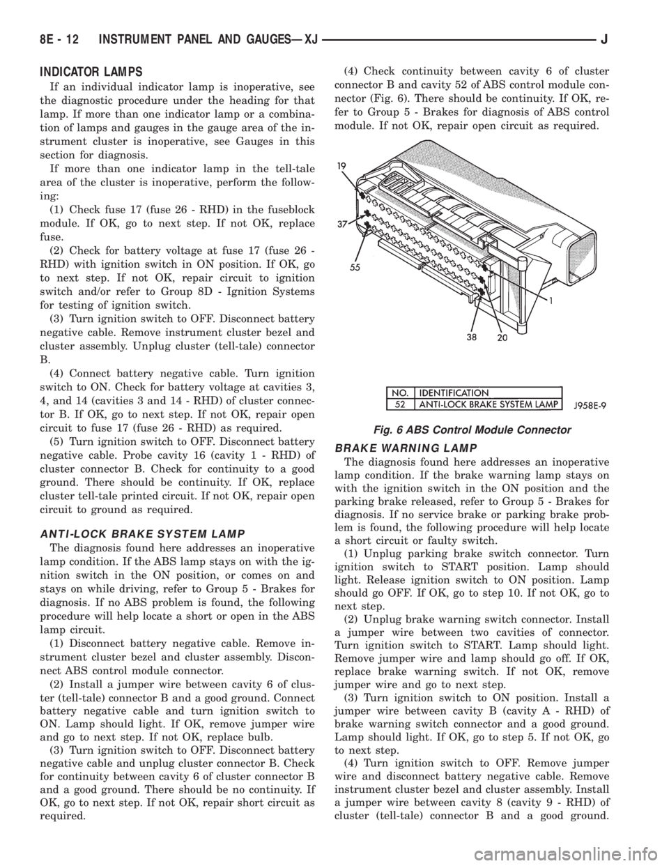
connector B and cavity 52 of ABS control module con-
nector (Fig. 6). There should be continuity. If OK, re-
fer to Group 5 - Brakes for diagnosis of ABS control
module. If not OK, repair open circuit as required.
BRAKE WARNING LAMP
The diagnosis found here addresses an inoperative
lamp condition. If the brake warning lamp stays on
with the ignition switch in the ON position and the
parking brake released, refer to Group 5 - Brakes for
diagnosis. If no service brake or parking brake prob-
lem is found, the following procedure will help locate
a short circuit or faulty switch.
(1) Unplug parking brake switch connector. Turn
ignition switch to START position. Lamp should
light. Release ignition switch to ON position. Lamp
should go OFF. If OK, go to step 10. If not OK, go to
next step.
(2) Unplug brake warning switch connector. Install
a jumper wire between two cavities of connector.
Turn ignition switch to START. Lamp should light.
Remove jumper wire and lamp should go off. If OK,
replace brake warning switch. If not OK, remove
jumper wire and go to next step.
(3) Turn ignition switch to ON position. Install a
jumper wire between cavity B (cavity A - RHD) of
brake warning switch connector and a good ground.
Lamp should light. If OK, go to step 5. If not OK, go
to next step.
(4) Turn ignition switch to OFF. Remove jumper
wire and disconnect battery negative cable. Remove
instrument cluster bezel and cluster assembly. Install
a jumper wire between cavity 8 (cavity 9 - RHD) of
cluster (tell-tale) connector B and a good ground.
Fig. 6 ABS Control Module Connector
8E - 12 INSTRUMENT PANEL AND GAUGESÐXJJ
Page 356 of 2198
Connect battery negative cable and turn ignition
switch to ON. Lamp should light. If OK, repair open
circuit to brake warning switch. If not OK, replace
bulb.
(5) Turn ignition switch to OFF and remove
jumper wire. Disconnect battery negative cable.
Check for continuity between cavity A (cavity B -
RHD) of brake warning switch connector and a good
ground with ignition switch in START position.
There should be continuity. If not OK, go to next
step.
(6) Turn ignition switch to OFF and remove
jumper wire. Disconnect battery negative cable. Un-
plug ignition switch connector. Check for continuity
between ignition switch connector cavity 3 and a
good ground. There should be no continuity. If OK, go
to next step. If not OK, repair short circuit between
ignition switch and brake warning switch connectors
as required.
(7) Check for continuity between ignition switch
connector cavity 3 and brake warning switch connec-
tor cavity A (cavity B - RHD). There should be conti-
nuity. If OK, go to next step. If not OK, repair open
circuit as required.
(8) Check for continuity between metal steering
column jacket and a good ground. There should be
continuity. If OK, go to next step. If not OK, refer to
Group 19 - Steering to check steering column ground
clip installation.
(9) Turn ignition switch to START position and
hold there. Check for continuity between terminal 3
of ignition switch and a good ground. There should
be continuity. If not OK, replace ignition switch.
(10) Unplug brake warning switch connector.
Check for continuity between parking brake switch
connector and a good ground. There should be no
continuity. If OK, go to next step. If not OK, repair
short circuit as required.
(11) Check for continuity between parking brake
switch connector and cavity B (cavity A - RHD) of
brake warning switch connector. There should be
continuity. If OK, replace parking brake switch. If
not OK, repair open circuit to brake warning switch
as required.
COOLANT TEMPERATURE WARNING LAMP
The diagnosis found here addresses an inoperative
lamp condition. If the problem being diagnosed is re-
lated to lamp accuracy, be certain to confirm that
problem is with lamp and not with cooling system
performance. Actual engine coolant temperature
should be checked with a test gauge or thermometer
before proceeding with lamp diagnosis. Refer to
Group 7 - Cooling System for more information.
(1) Turn ignition switch to START position. Lamp
should light. If OK, go to next step. If not OK, go to
step 3.(2) Turn ignition switch to ON. Disconnect coolant
temperature switch connector (Fig. 1). Jump switch
connector to ground. Lamp should light. If OK, re-
place switch. If not OK, go to next step.
(3) Turn ignition switch to OFF. Disconnect battery
negative cable. Unplug coolant temperature switch
connector. Remove instrument cluster bezel and clus-
ter assembly. Disconnect cluster connector A and
probe cavity A1. Check for continuity to a good
ground. There should be no continuity. If OK, go to
next step. If not OK, repair short circuit to coolant
temperature switch or ignition switch as required.
(4) Connect cluster connector A to cluster. Install a
jumper wire from cavity A1 of cluster connector A to
a good ground. Connect battery negative cable and
turn ignition switch to ON. Lamp should light. If OK,
repair open circuit to coolant temperature switch or
ignition switch as required. If not OK, replace bulb.
FOUR-WHEEL DRIVE INDICATOR LAMPS
(1) Apply parking brake, start engine, vehicle in
4WD Lock or 4WD.
(2) Unplug switch and touch harness side of wire
to ground. Lamp should light. If OK, check switch
operation, replace if bad. If bulb is OK, repair open
to indicator.
GENERATOR WARNING LAMP
(1) Disconnect battery negative cable and unplug
PCM connector. Install a jumper wire between cavity
36 of PCM connector (Fig. 5) and a good ground. Con-
nect battery negative cable and turn ignition switch
to ON. Lamp should light. Unplug jumper wire and
lamp should go off. If OK, refer to Powertrain Diag-
nostic Procedures to check PCM. If not OK, go to
next step.
(2) Turn ignition switch to OFF and disconnect
battery negative cable. Remove instrument cluster
bezel and cluster assembly. Install a jumper wire be-
tween cavity B8 of cluster connector A and a good
ground. Connect battery negative cable and turn ig-
nition switch to ON. Lamp should light. If OK, go to
next step. If not OK, replace bulb.
(3) Turn ignition switch to OFF and disconnect
battery negative cable. Unplug cluster connector A.
Probe cavity B8 of cluster connector A and check for
continuity to a good ground. There should be no con-
tinuity. If OK, go to next step. If not OK, repair short
circuit as required.
(4) Check for continuity between cavity B8 of clus-
ter connector A and cavity 36 of PCM connector.
There should be continuity. If not OK, repair open
circuit as required.
HEADLAMP HIGH BEAM INDICATOR LAMP
(1) Check that headlamp high beams are func-
tional. If OK, go to next step. If not OK, refer to
Group 8L - Lamps for diagnosis of headlamp system.
JINSTRUMENT PANEL AND GAUGESÐXJ 8E - 13
Page 357 of 2198
(2) Disconnect battery negative cable. Remove in-
strument cluster bezel and cluster assembly. Unplug
cluster connector A. Connect battery negative cable.
Turn headlamps on and select high beam. Check for
battery voltage at cavity A4 of cluster connector A. If
OK, replace indicator bulb. If not OK, repair circuit
to headlamp dimmer (multi-function) switch as re-
quired.
LOW FUEL WARNING LAMP
(1) Check that fuel gauge is operating as designed.
See Fuel Gauge Calibration chart in Specifications. If
OK, go to next step. If not OK, see Fuel Gauge in
this section for diagnosis.
(2) With at least 10 gallons of fuel in fuel tank, un-
plug fuel tank sending unit connector. Turn ignition
switch to ON and wait 10 seconds. Lamp (LED)
should light. Reconnect fuel tank sending unit and
wait 20 seconds. Lamp (LED) should go off. If not
OK, replace low fuel warning lamp module.
LOW OIL PRESSURE WARNING LAMP
The diagnosis found here addresses an inoperative
lamp condition. If the problem being diagnosed is re-
lated to lamp accuracy, be certain to confirm that
problem is with lamp and not with engine oiling sys-
tem. Actual engine oil pressure should be checked
with a test gauge before you proceed with lamp diag-
nosis. Refer to Group 9 - Engines for more informa-
tion.
(1) Turn ignition switch to ON. Lamp should light.
Start engine. Lamp should go off. If not OK, turn en-
gine off and go to next step.
(2) Unplug connector at oil pressure switch (Fig.
3). The switch is located on right side of engine block.
On 2.5L engine, it is just forward of ignition distrib-
utor and just to the rear of generator mounting
bracket. On 4.0L engine, it is just to the rear of igni-
tion distributor and above oil filter adapter. Install a
jumper wire from connector to a good ground. Turn
ignition switch to ON. Lamp should light. Unplug
jumper wire. Lamp should go out. If OK, replace oil
pressure switch. If not OK, go to next step.
(3) Turn ignition switch to OFF. Disconnect battery
negative cable. Remove instrument cluster bezel and
cluster assembly. Install a jumper wire from cavity
B7 (cavity B8 - RHD) of cluster connector A to a good
ground. Connect battery negative cable and turn ig-
nition switch to ON. Lamp should light. If OK, go to
next step. If not OK, replace lamp bulb.
(4) Turn ignition switch to OFF. Disconnect battery
negative cable. Unplug instrument cluster connector
A. Check continuity between cavity B7 (cavity B8 -
RHD) of cluster connector A and a good ground.
There should be no continuity. If OK, go to next step.
If not OK, repair short circuit as required.
(5) Check continuity between cavity B7 (cavity B8
- RHD) of cluster connector A and oil pressure switchconnector. There should be continuity. If not OK, re-
pair open circuit as required.
LOW WASHER FLUID WARNING LAMP
(1) Unplug washer fluid level switch connector.
Turn ignition switch to ON. Check for battery voltage
at connector cavity A. If OK, turn ignition switch to
OFF and go to next step. If not OK, repair open cir-
cuit to fuse F6 in PDC.
(2) Install a jumper wire from cavity A to cavity B
of washer fluid level switch connector. Turn ignition
switch to ON. Lamp should light. Unplug jumper and
lamp should go OFF. If OK, replace washer fluid
level switch. If not OK, go to next step.
(3) Turn ignition switch to OFF. Disconnect battery
negative cable. Remove instrument cluster bezel and
cluster assembly. Unplug instrument cluster (tell-
tale) connector B. Check continuity between cavity 16
(cavity 1 - RHD) of cluster connector B and a good
ground. There should be continuity. If OK, plug clus-
ter connector B back into cluster and go to next step.
If not OK, repair open circuit to ground as required.
(4) Connect battery negative cable. Install a
jumper wire from a 12-volt battery feed to cavity 1
(cavity 16 - RHD) of cluster connector B. Lamp
should light. If OK, go to next step. If not OK, re-
place bulb.
(5) Disconnect battery negative cable. Unplug clus-
ter connector B. Check continuity between cavity 1
(cavity 16 - RHD) of cluster connector B and a good
ground. There should be no continuity. If OK, go to
next step. If not OK, repair short circuit to switch as
required.
(6) Check continuity between cavity 1 (cavity 16 -
RHD) of cluster connector B and cavity B of washer
fluid level switch connector. There should be continu-
ity. If not OK, repair open circuit to switch as re-
quired.
MALFUNCTION INDICATOR LAMP
The diagnosis found here addresses an inoperative
lamp condition. If the lamp comes on and stays on
with engine running, refer to Group 14 - Fuel System
for diagnosis. If no fuel or emission system problem
is found, the following procedure will help locate a
short or open in the lamp circuit.
(1) Disconnect battery negative cable. Unplug PCM
connector. Install a jumper wire from cavity 32 of
PCM connector (Fig. 5) to a good ground. Connect
battery negative cable. Turn ignition switch to ON.
Lamp should light. Remove jumper wire and lamp
should go OFF. If OK, refer to Powertrain Diagnostic
Procedures to check PCM. If not OK, go to next step.
(2) Turn ignition switch to OFF. Disconnect battery
negative cable. Remove instrument cluster bezel and
cluster assembly. Install a jumper wire from cavity 2
(cavity 15 - RHD) of cluster (tell-tale) connector B to
a good ground. Connect battery negative cable. Turn
8E - 14 INSTRUMENT PANEL AND GAUGESÐXJJ
Page 358 of 2198
ignition switch to ON. Lamp should light. If OK, go
to next step. If not OK, replace bulb.
(3) Turn ignition switch to OFF. Disconnect battery
negative cable. Unplug cluster connector B. Check for
continuity between cavity 2 (cavity 15 - RHD) of clus-
ter connector B and a good ground. There should be
no continuity. If OK, go to next step. If not OK, re-
pair short circuit to PCM as required.
(4) Check continuity between cavity 2 (cavity 15 -
RHD) of cluster connector B and cavity 32 of PCM
connector. There should be continuity. If not OK, re-
pair open circuit to PCM as required.
SEAT BELT REMINDER LAMP
(1) Refer to Group 8U - Chime/Buzzer Warning
Systems to check chime/buzzer module operation. If
OK, go to next step. If not OK, replace chime/buzzer
module.
(2) Disconnect battery negative cable. Remove in-
strument cluster bezel and cluster assembly. Unplug
cluster (tell-tale) connector B. Check for continuity
between cavity 16 (cavity 1 - RHD) of cluster connec-
tor B and a good ground. There should be continuity.
If OK, plug cluster connector B back into cluster and
go to next step. If not OK, repair open circuit to
ground as required.
(3) Connect battery negative cable. Install a
jumper wire between a 12-volt battery feed and cav-
ity 15 (cavity 2 - RHD) of cluster connector B. Lamp
should light. If OK, go to next step. If not OK, re-
place bulb.
(4) Disconnect battery negative cable. Unplug
chime/buzzer module from fuseblock module (connec-
tor near fuseblock module - RHD). Unplug cluster
connector B. Check for continuity between cavity 15
(cavity 2 - RHD) of cluster connector B and a good
ground. There should be no continuity. If OK, go to
next step. If not OK, repair short circuit to chime/
buzzer module as required.
(5) Check continuity between cavity 15 (cavity 2 -
RHD) of cluster connector B and cavity for terminal
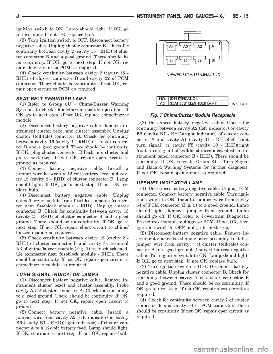
A3 of chime/buzzer module (Fig. 7) in fuseblock mod-
ule (connector near fuseblock module - RHD). There
should be continuity. If not OK, repair open circuit to
chime/buzzer module as required.
TURN SIGNAL INDICATOR LAMPS
(1) Disconnect battery negative cable. Remove in-
strument cluster bezel and cluster assembly. Probe
cavity A3 of cluster connector A. Check for continuity
to a good ground. There should be continuity. If OK,
go to next step. If not OK, repair open circuit to
ground.
(2) Connect battery negative cable. Install a
jumper wire from cavity A2 (left indicator) or cavity
B6 (cavity B7 - RHD)(right indicator) of cluster con-
nector A to a 12-volt battery feed. Lamp should light.
If OK, continue to next step. If not OK, replace bulb.(3) Disconnect battery negative cable. Check for
continuity between cavity A2 (left indicator) or cavity
B6 (cavity B7 - RHD)(right indicator) of cluster con-
nector A and cavity A1 (cavity 11 - RHD)(left front
turn signal) or cavity F2 (cavity 10 - RHD)(right
front turn signal) of bulkhead disconnect (dash to in-
strument panel connector B - RHD). There should be
continuity. If OK, refer to Group 8J - Turn Signal
and Hazard Warning Systems for further diagnosis.
If not OK, repair open circuit as required.
UPSHIFT INDICATOR LAMP
(1) Disconnect battery negative cable. Unplug PCM
connector. Connect battery negative cable. Turn igni-
tion switch to ON. Install a jumper wire from cavity
54 of PCM connector (Fig. 5) to a good ground. Lamp
should light. Remove jumper from ground. Lamp
should go off. If OK, refer to Powertrain Diagnostic
Procedures manual to diagnose PCM. If not OK, turn
ignition switch to OFF and go to next step.
(2) Disconnect battery negative cable. Remove in-
strument cluster bezel and cluster assembly. Install a
jumper wire from cavity 7 of cluster (tell-tale) con-
nector B to a good ground. Connect battery negative
cable. Turn ignition switch to ON. Lamp should light.
If OK, go to next step. If not OK, replace bulb.
(3) Turn ignition switch to OFF. Disconnect battery
negative cable. Unplug cluster connector B. Check for
continuity between cavity 7 of cluster connector B
and a good ground. There should be no continuity. If
OK, go to next step. If not OK, repair short circuit as
required.
(4) Check for continuity between cavity 7 of cluster
connector B and cavity 54 of PCM connector. There
should be continuity. If not OK, repair open circuit as
required.
Fig. 7 Chime/Buzzer Module Receptacle
JINSTRUMENT PANEL AND GAUGESÐXJ 8E - 15
Page 359 of 2198
CLUSTER ILLUMINATION LAMPS
(1) Check fuse 19 (fuse 25 - RHD) in fuseblock
module. If OK, go to next step. If not OK, replace
fuse.
(2) Turn park lamps on at headlamp switch. Rotate
headlamp switch knob counterclockwise to just before
interior lamps detent. Check for battery voltage at
fuse 19 (fuse 25 - RHD) in fuseblock module. Rotate
headlamp switch clockwise while observing test volt-
meter. Reading should go from battery voltage to zero
volts. If OK, go to next step. If not OK, repair open
circuit to headlamp switch or refer to Group 8L -
Lamps to diagnose headlamp switch.
(3) Disconnect battery negative cable. Remove in-
strument cluster bezel and cluster assembly. Unplug
cluster connector A. Connect battery negative cable.Turn park lamps on at headlamp switch. Rotate
headlamp switch knob counterclockwise to just before
interior lamps detent. Check for battery voltage at
cavity A7 (cavity A6 - RHD) of cluster connector A. If
OK, go to next step. If not OK, repair open circuit to
fuse as required.
(4) Turn park lamps off. Disconnect battery nega-
tive cable. Remove fuse 19 (fuse 25 - RHD) from fuse-
block module. Probe cavity A7 (cavity A6 - RHD) of
cluster connector A. Check for continuity to a good
ground. There should be no continuity. If OK, go to
next step. If not OK, repair short circuit as required.
(5) Probe cavity A3 of cluster connector A. Check
for continuity to ground. There should be continuity.
If not OK, repair open circuit as required.
8E - 16 INSTRUMENT PANEL AND GAUGESÐXJJ
Page 360 of 2198
SERVICE PROCEDURES
CLUSTER ASSEMBLY REMOVE/INSTALL
(1) Disconnect battery negative cable.
(2) Remove upper and lower steering column
shrouds and steering column to instrument panel be-
zel gap hider. If equipped with tilt steering, apply
tape to tilt mechanism on top of steering column to
protect instrument panel bezel from damage during
removal.
(3) Remove 4 instrument cluster bezel attaching
screws and remove bezel. Bezel is snap fit at loca-
tions shown (Fig. 8).
(4) Remove cigar lighter housing attaching screws
(Fig. 9).
(5) If equipped, remove switch housing(s) attaching
screws (Fig. 9).(6) Remove cluster assembly attaching screws (Fig.
9).
(7) Pull cluster assembly far enough out to discon-
nect 2 cluster harness connectors from the rear. Re-
move cluster assembly.
(8) Reverse removal procedures to install.
GAUGES REMOVE/INSTALL
(1) Remove cluster assembly as described in Clus-
ter Assembly Remove/Install.
Fig. 8 Cluster Bezel Remove/Install
Fig. 9 Cluster Assembly Remove/Install
JINSTRUMENT PANEL AND GAUGESÐXJ 8E - 17