engine JEEP CJ 1953 Service Manual
[x] Cancel search | Manufacturer: JEEP, Model Year: 1953, Model line: CJ, Model: JEEP CJ 1953Pages: 376, PDF Size: 19.96 MB
Page 314 of 376
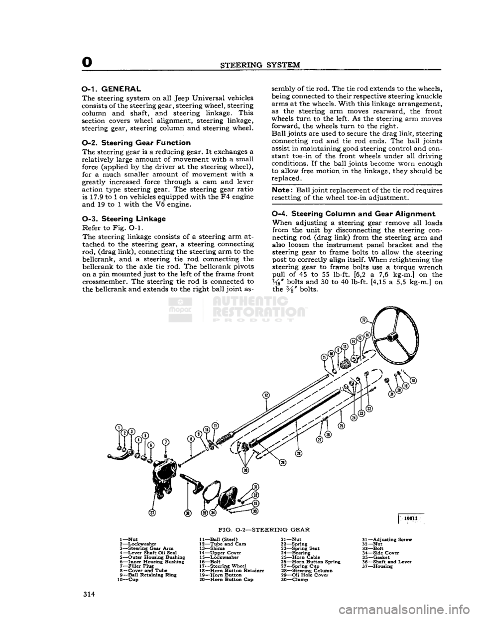
STEERING
SYSTEM
O-L
GENERAL
The
steering system on all Jeep Universal vehicles
consists of the steering gear, steering wheel, steering column and shaft, and steering linkage.
This
section covers wheel alignment, steering linkage,
steering gear, steering column and steering wheel.
0-2. Steering
Gear
Function
The
steering gear is a reducing gear. It exchanges a
relatively
large amount of movement with a small force (applied by the driver at the steering wheel), for a much smaller amount of movement with a
greatly increased force through a cam and lever
action type steering gear. The steering gear ratio is 17.9 to 1 on vehicles equipped with the F4
engine
and
19 to 1 with the V6 engine.
0-3. Steering
Linkage
Refer
to Fig. O-l.
The
steering linkage consists of a steering arm at
tached to the steering gear, a steering connecting
rod,
(drag
link),
connecting the steering arm to the
beilcrank,
and a steering tie rod connecting the
beilcrank
to the axle tie rod. The beilcrank pivots
on a pin mounted just to the left of the frame front crossmember. The steering tie rod is connected to
the beilcrank and
extends
to the right
ball
joint as sembly of tie rod. The tie rod
extends
to the wheels,
being connected to their respective steering knuckle
arms
at the wheels.
With
this linkage arrangement,
as the steering arm
moves
rearward,
the front
wheels
turn
to the left. As the steering arm
moves
forward,
the wheels
turn
to the right.
Ball
joints are used to secure the drag
link,
steering
connecting rod and tie rod ends. The
ball
joints
assist in maintaining
good
steering control and con
stant toe-in of the front wheels under all driving conditions. If the
ball
joints
become
worn enough
to allow free motion in the linkage, they should be,
replaced.
Note:
Ball
joint replacement of the tie rod requires
resetting of the wheel toe-in adjustment.
0-4.
Steering
Column
and Gear
Alignment
When
adjusting a steering gear remove all loads
from
the unit by disconnecting the steering con
necting rod (drag
link)
from the steering arm and
also
loosen
the instrument panel bracket and the
steering gear to frame
bolts
to allow the steering
post
to correctly align itself. When retightening the
steering gear to frame
bolts
use a torque wrench
pull
of 45 to 55 lb-ft. [6,2 a 7,6 kg-m.] on the
Vk*
bolts
and 30 to 40 lb-ft. [4,15 a 5,5 kg-m.] on the
Vs"
bolts. 10811
FIG.
0-2—STEERING
GEAR
1—Nut
2
—Lockwasher
3—
Steering
Gear
Arm 4—
Lever
Shaft Oil Seal
5—
Outer
Housing Bushing
6—
Inner
Housing Bushing 7—
Filler
Plug
8—
Cover
and Tube
9—
Ball
Retaining
Ring
10—Cup
11—
Ball
(Steel)
12—
Tube
and Cam
13—
Shims
14—
Upper
Cover
15—
Lockwasher
16—
Bolt
17—
Steering
Wheel 18—
Horn
Button Retainer
19—
Horn
Button
20—
Horn
Button Cap 21— Nut
22—
Spring
23—
Spring
Seat
24—
Bearing
25—
Horn
Cable
26—
Horn
Button Spring
27—
Spring
Cup
28—
Steering Column
29—
Oil
Hole
Cover
30—
Clamp
31—
Adjusting
Screw
32— Nut
33—
Bolt
34—
Side
Cover
35—
Gasket
36—
Shaft
and
Lever
37—
Housing
314
Page 320 of 376
STEERING
SYSTEM
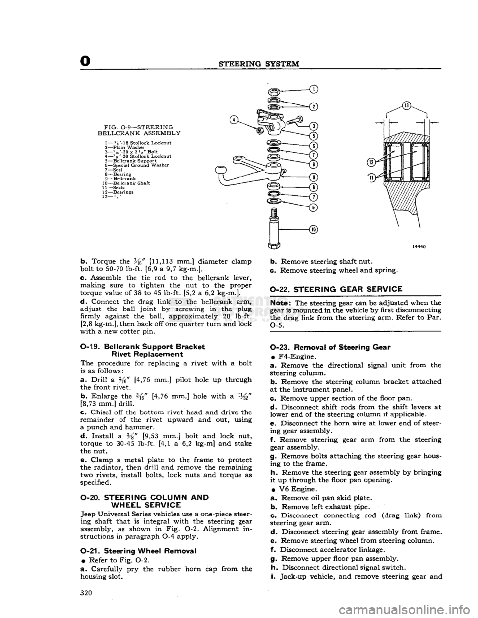
FIG.
0-9—STEERING
BELLCRANK
ASSEMBLY
1— 5s'-18
Stollock
Lockout
2—
Plain
Washer
3— 7 us"-20
x
2 l2' Bolt
4—
71«
*-20
Stollock
Locknut
5—
Beilcrank
Support
6—
Special
Ground
Washer
7— Seal
8—
Bearing
9— Beilcrank
10— Beilcrank
Shaft
11—
Seals
12—
Bearings
13— } s *
b.
Torque the
Vfc"
[11,113
mm.] diameter elamp
bolt to
50-70
lb-ft. [6,9 a 9,7 kg-m.].
c.
Assemble the tie rod to the beilcrank lever,
making
sure to tighten the nut to the proper
torque value of 38 to 45 lb-ft. [5,2 a 6,2 kg-m.].
d.
Connect the drag
link
to the beilcrank arm,
adjust
the
ball
joint by screwing in the plug firmly against the
ball,
approximately 20 lb-ft. [2,8 kg-m.], then back off one quarter
turn
and lock
with
a new cotter pin.
0-19.
Beilcrank
Support
Bracket
Rivet
Replacement
The
procedure for replacing a rivet with a bolt
is as follows:
a.
Drill
a [4,76 mm.] pilot
hole
up through
the front rivet.
b.
Enlarge
the [4,76 mm.]
hole
with a %"
[8,73 mm.]
drill.
c.
Chisel
off the
bottom
rivet head and drive the
remainder
of the rivet upward and out, using
a
punch and hammer.
d.
Install
a %" [9,53 mm.] bolt and lock nut,
torque to
30-45
lb-ft. [4,1 a 6,2 kg-m] and stake
the nut.
e.
Clamp
a metal plate to the frame to protect
the radiator, then
drill
and remove the remaining two rivets, install bolts, lock nuts and torque as
specified.
O-20.
STEERING
COLUMN
AND
WHEEL SERVICE
Jeep
Universal
Series vehicles use a
one-piece
steer
ing
shaft that is integral with the steering gear
assembly, as shown in Fig. 0-2. Alignment in
structions in paragraph 0-4 apply.
0-21.
Steering
Wheel Removal •
Refer to Fig. 0-2.
a.
Carefully
pry the rubber horn cap from the housing slot.
b.
Remove steering shaft nut.
c.
Remove steering wheel and spring.
0-22.
STEERING GEAR SERVICE
Note:
The steering gear can be adjusted when the
gear is mounted in the vehicle by first disconnecting
the drag
link
from the steering arm. Refer to Par.
Q-5.
0-23.
Removal
of
Steering Gear
•
F4-Engine.
a.
Remove the directional signal unit from the steering column.
b.
Remove the steering column bracket attached
at the instrument panel.
c.
Remove upper section of the floor pan.
d.
Disconnect shift rods from the shift levers at
lower end of the steering column if applicable.
e.
Disconnect the horn wire at lower end of steer
ing
gear assembly.
f.
Remove steering gear arm from the steering gear assembly.
g.
Remove
bolts
attaching the steering gear hous
ing
to the frame.
h.
Remove the steering gear assembly by bringing
it
up through the floor pan opening.
•
V6 Engine.
a.
Remove oil pan
skid
plate.
b.
Remove
left
exhaust pipe.
c.
Disconnect connecting rod (drag
link)
from
steering gear arm.
d.
Disconnect steering gear assembly from frame.
e.
Remove steering wheel from steering column.
f. Disconnect accelerator linkage.
g.
Remove upper floor pan assembly.
h.
Disconnect directional signal switch.
i.
Jack-up
vehicle, and remove steering gear and
320
Page 322 of 376
o
STEERING
SYSTEM 0-28.
SBKF1CE
DIAGNOSIS
SYMPTOMS PROBABLE REMEDY
Hard Steering
Lack
of Lubrication Lubricate all Connections
Tie
Rod
Ends
Worn.
Replace
Connecting Rod
Ball
Joints
Tight. Adjust
Cross
Shaft Improperly Adjusted Adjust Steering
Gear
Parts
Worn...................
Replace
Steering
Loose
Tie
Rod
Ends
Worn
Replace
Connecting Rod
Ball
Sockets
Worn
Replace
Steering
Gear
Parts
Worn.
Replace
Steering
Gear
Improperly Adjusted.
......
Adjust
Road Shook; Steering Connecting Rod too Tight;
Axle
Spring
Clip
Loose; Wheel Bearings Loose;
Poor
Shock Absorber
Control,
Turning Radius
Short One
Side
Center
Bolt
in Spring
Sheered
Off,
Axle
Shifted, Steering Arm Bent, Steering Arm not Properly Located
on
Steering
Gear.
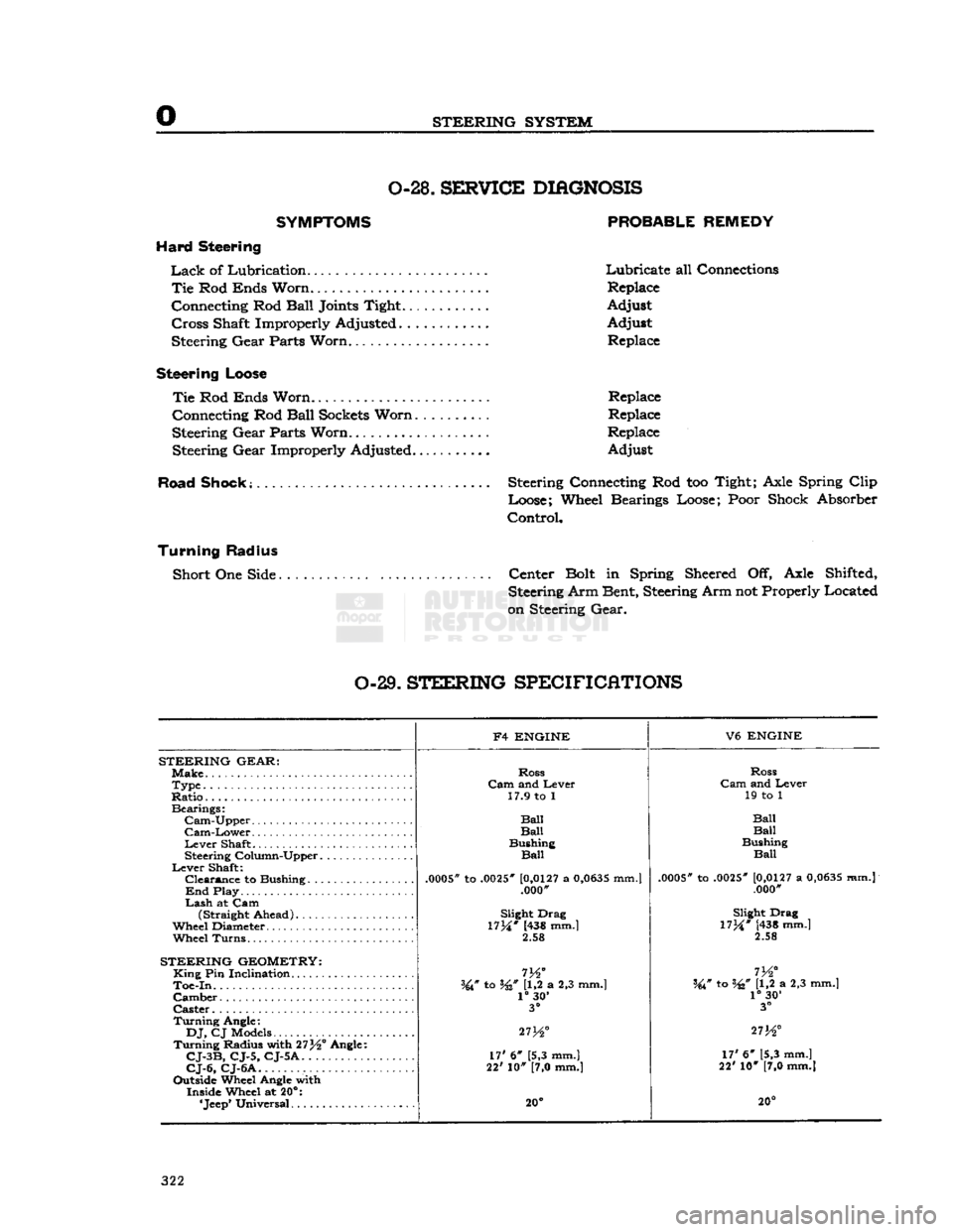
0-29.
STEERING
SPECIFICATIONS
F4
ENGINE
V6
ENGINE
STEERING
GEAR:
Make.
Ross
Ross
Type
Cam
and Lever
Cam
and Lever
Ratio..
17.9 to 1
19 to 1
Bearings:
Ball
Cam-Upper
Ball Ball
Cam-Lower
Ball Ball
Lever
Shaft Bushing
Bushing
Steering Column-Upper
Ball
Ball
Lever
Shaft:
.0005*
to
.0025"
[0,0127
a
0,0635
mm.]
Clearance
to Bushing
.0005"
to
.0025"
[0,0127
a
0,0635
mm.j
.0005*
to
.0025"
[0,0127
a
0,0635
mm.]
End
Play .000'
.000"
Lash
at Cam (Straight Ahead) Slight Drag
Slight Drag
Wheel Diameter.
17M*
(438 mm.]
17M*
[438 mm.]
Wheel
Turns.
2.58
2.58
STEERING
GEOMETRY:
King
Pin Inclination
m°
I
72
Toe-In.
W to W U,2 a 2,3 mm.] W to W [1,2 a 2,3 mm.]
Camber
1°
30'
1°
30'
Caster
3°
3°
Turning
Angle:
27K°
DJ,
CJ Models
27K° 273^°
Turning
Radius with 27^° Angle: 17' 6" [5,3 mm.]
CJ-3B,
CJ-5, CJ-5A.
17' 6" [5,3 mm.]
17' 6" [5,3 mm.]
CJ-6,
CJ-6A
22' 10" [7,0 mm.]
22' 10" [7,0 mm.]
Outside Wheel Angle with Inside Wheel at 20°:
20° 20°
322
Page 340 of 376
Q
WHEELS
11463
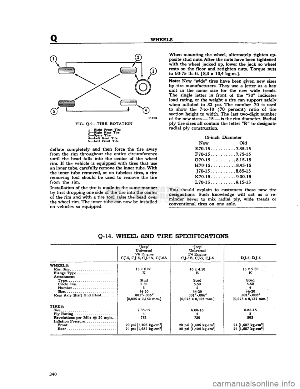
FIG.
Q-9—TIRE
ROTATION
1—
Right
Front
Tire
2—
Right
Rear
Tire
3—
Spare
Tire
4—
-Left
Rear
Tire
5—
Left
Front
Tire
deflate completely and then force the tire away
from
the rim throughout the entire circumference
until
the bead falls into the center of the wheel
rim.
If the vehicle is equipped with tires that use
an
inner tube, carefully remove the inner tube.
With
the inner tube removed, or on tubeless tires, a tire
removing tool should be used to remove the tire
from
the rim.
Installation
of the tire is made in the same manner
by first dropping one side of the tire into the center
of the rim and with a tire tool raise the bead over
the wheel
rim.
The inner tube can now be installed
on vehicles so equipped.
When
mounting the wheel, alternately tighten op
posite stud nuts. After the nuts have been tightened
with
the wheel jacked up, lower the
jack
so wheel rests on the floor and retighten nuts. Torque nuts
to 60-75 lb.-ft. [8,3 a 10,4 kg-m.].
Note:
New "wide" tires have been given new sizes
by tire manufacturers. They use a letter as a key
unit
in the name size for the new wide treads.
The
single letter in front of the "70" indicates load rating, or the weight a tire can support safely
when inflated to 32 psi. The number 70 is used to show the
7-to-10
(70 percent) ratio of tire section height to width. The last two-digit number of the new sizes— 15 —
is
the rim diameter.
Radial
ply
tire sizes all contain the letter
"R"
to designate
radial
ply construction.
15-inch
Diameter
New Old
E70-15
7.35-15
F70-15
.7.75-15
G70-15
8.15-15
H70-15
8.45-15
J70-15
.8.85-15
K70-15
. .... .9.00-15
L70-15
9.15-15
You
should explain to customers
these
new tire
designations. Such knowledge
will
act as a re
minder
never to mix
radial
ply, wide treads or
conventional tires on one axle.
0-14.
WHEEL
AND
TIRE
SPECIFICATIONS
'Jeep'
Universal
V6
Engine
CJ-5,
CJ-6,
CJ-5A,
CJ-6A
'Jeep*
Universal
F4
Engine
CJ-3B,
CJ-5,
CJ-6
DJ-5,
DJ-6
WHEELS:
Rim
Size 15 x
6.00
16 x 4.50
15 x 5.50
K
E
K
Attachment
Type
Stud
Stud Stud
Circle
Dia 5.50 5.50 5.50
5 5
4
Size
H-20
H-20
H-20
Rear
Axle Shaft End Float .001*-.006"
.001"-.006" .001 *-.006"
[0 ,025 a 0,152 mm.)
[0,025 a 0,152 mm.] [0,025 a 0,152 mm.]
TIRES:
Size.
7.35-15
6.00-16
6.85-15
Ply
Rating 4
4 2
Revolutions per Mile @ 30 mph.. . 781 730 803
Inflation
Pressure
Front
20
psi
[1,406 kg-cm2]
20 psi [1,406 kg-cm2] 24 [1,687 kg-cm*]
Rear
24
psi
[1,687 kg-cm*]
20 psi [1,406 kg-cm2] 24 [1,687 kg-cm*] 340
Page 341 of 376
'Jeep'
UNIVERSAL
SERIES
SERVICE
MANUAL
R
FRAME
Contents
SUBJECT
PAR.
Draw
Bar
R-6
Frame
Alignment
.R-2
Frame
Dimensions
.R-3
Front
Axle Alignment.
R-5
Straightening
Frame
R-4
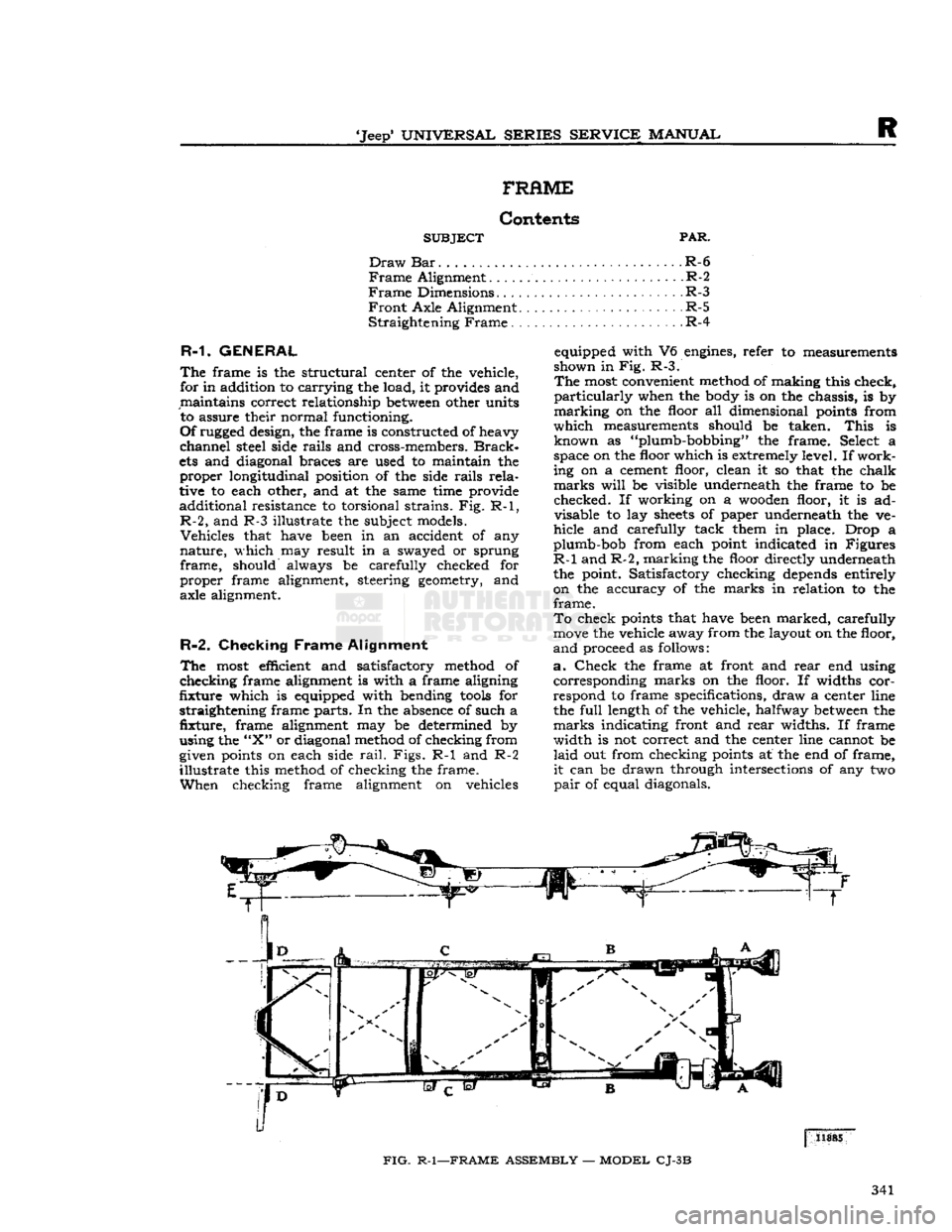
R-1.
GENERAL
equipped with V6 engines, refer
to
measurements
The
frame
is the
structural center
of
the vehicle,
B£?wn
in
FiB-
R"f
, _ , r' .
for in addition
to
carrying
the load,
it
provides and The inost convenient method
of
making this check,
maintains
correct relationship
between
other units
Particularly
when
the
body
is on the
chassis,
is by
to assure their normal functioning. marking
on the
floor
all
dimensional points from
Of
rugged design, the frame
is
constructed of heavy
fhlch
measurements should
be
taken.
This
is
channel
steel side
rails
and cross-members.
Brack-
known
a\
Plumb-bobbing
the
frame Select
a
ets and diagonal braces
are
used
to
maintain
the
?Pace
on the
floof
^hlch
»
extr«nely
level If
work-
proper
longitudinal position
of the
side
rails
rela-
ing Pn
a.,fPen^
c*ean
* s°
that
the fha*k
tive
to
each other, and
at the
same time provide
*****
Jl!*
be
vJs.lble
underneath
the
frame
to be
additional
resistance
to
torsional strains. Fig. R-1, checked
If
workmg
on a
wooden
floor
it is ad-
R-2,
and R-3 illustrate
the
subject models. disable
la^
f f * V
Underneath
*he ve"
Vehicles
that have been
in an
accident
of any
hide
and
carefully tack them
m
place. Drop
a
nature,
which
may
result
in a
swayed
or
sprung gumb-bob from each point indicated
in
Figures
frame,
should always
be
carefully checked
for ^
an?
L'maJkl?g the uflo?r
Meetly underneath
proper
frame alignment, steering geometry,
and the
point. Satisfactory checking depends entirely
axle alignment.
on the
accuracy
of the
marks
in
relation
to the
frame.
To
check points that have been marked, carefully
move
the vehicle away from the layout on the floor,
R-2.
Checking
Frame
Alignment
anci
proceed
as
follows:
The
most efficient
and
satisfactory method
of a.
Check
the
frame
at
front
and
rear
end
using
checking
frame alignment
is
with
a
frame aligning corresponding marks
on the
floor.
If
widths
cor-
fixture
which
is
equipped with bending
tools
for
respond
to
frame specifications, draw
a
center line
straightening frame parts. In the absence
of
such
a the
full
length
of
the vehicle, halfway
between
the
fixture,
frame
alignment
may be
determined
by
marks indicating front and
rear
widths.
If
frame
using the
"X"
or diagonal method of checking from width
is not
correct and
the
center line cannot
be
given points
on
each side
rail.
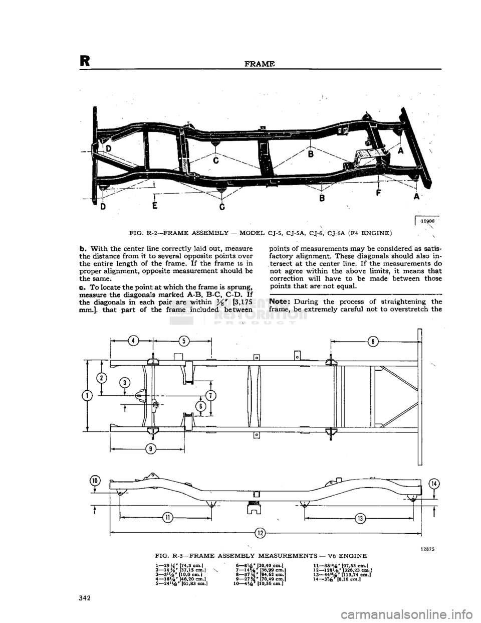
Figs.
R-1 and R-2
laid
out
from checking points
at the
end
of
frame,
illustrate
this method
of
checking
the
frame.
it
can
be
drawn through intersections
of
any
two
When
checking frame alignment
on
vehicles
pair
of
equal diagonals.
FIG.
R-1—FRAME
ASSEMBLY
—
MODEL
CJ-3B
341
Page 342 of 376
R
FRAME
11900
FIG.
R-2—FRAME ASSEMBLY
—
MODEL
CJ-5,
CJ-5A,
CJ-6,
CJ-6A
(F4
ENGINE)
b.
With
the
center line correctly
laid
out,
measure
the distance from
it to
several
opposite
points over
the entire length
of the
frame.
If the
frame
is in
proper
alignment,
opposite
measurement should
be
the same.
c.
To locate the point at
which
the
frame
is
sprung,
measure
the
diagonals marked
A-B,
B-C,
C-D.
If
the diagonals
in
each
pair
are
within [3,175
mm.],
that
part
of the
frame included between points
of
measurements may
be
considered
as
satis
factory
alignment. These diagonals should also
in
tersect
at the
center line.
If the
measurements
do
not agree within
the
above limits,
it
means that
correction
will
have
to be
made between
those
points that are not equal.
Note:
During
the
process
of
straightening
the
frame,
be
extremely careful
not to
overstretch
the
JiL
R
TET
12875
FIG.
R-3—FRAME ASSEMBLY MEASUREMENTS
— V6
ENGINE
1—
29H'
[74,3 cm.l 6—8[20.40 Cm.|
11—38»4*
[97,55 cm.)
2—
14 %' [37,15 cm.|
\ 7—14»4*t36,99
cm.l
12—128Mb'
[326,23
cm.]
3—
3i*4*
110,0 cm.l
8—37K*
[94.62
cm.l
13—44"^' [113,74 cm.l
4— 18«4* [46,20
cm.|
9—27**' [70,49 cm.j 14—316'
[8,18
cm.l
5—
24114»
[61,83 cm.) 10—4%* [10.56 cm.] 342
Page 343 of 376
'Jeep*
UNIVERSAL
SERIES
SERVICE
MANUAL
R
frame.
This
could cause the already aligned sec
tions of the frame to
become
misaligned or weak ened.
R-3.
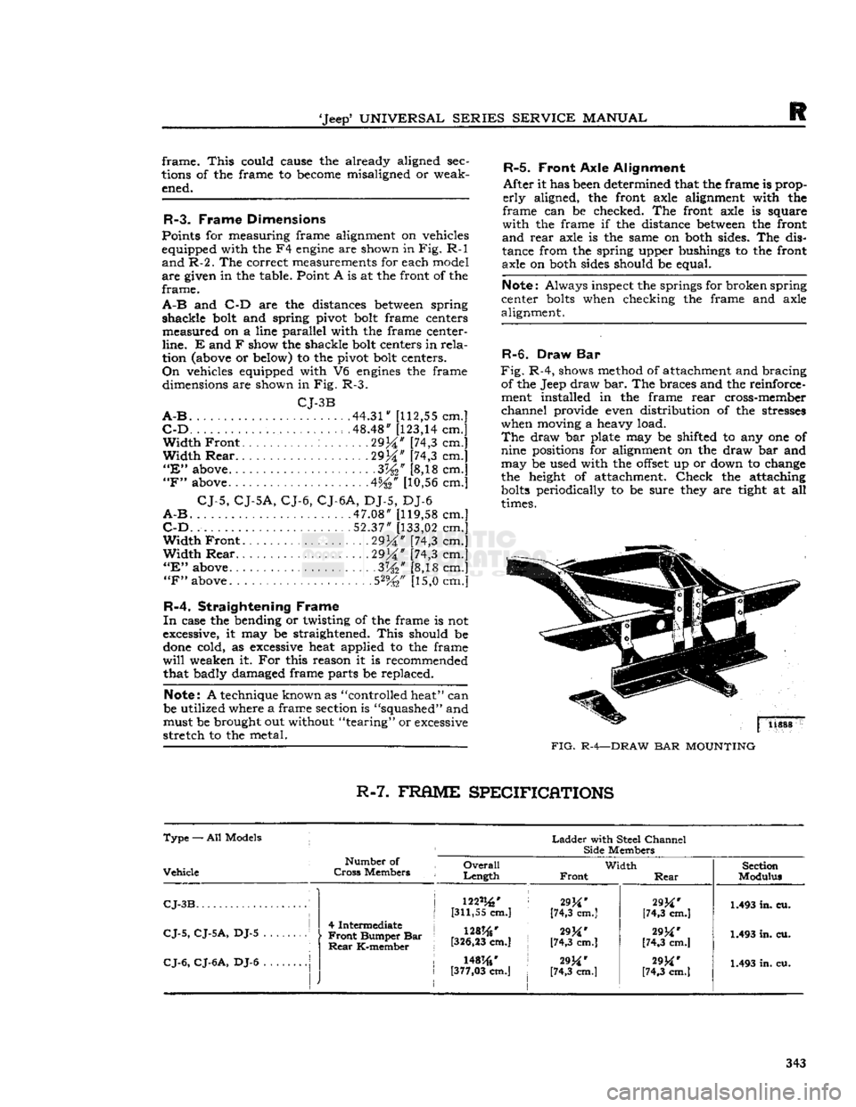
Frame Dimensions
Points for measuring frame alignment on vehicles
equipped with the F4
engine
are shown in
Fig.
R-l
and
R-2.
The correct measurements for each model
are
given in the table. Point A is at the front of the
frame.
A-B
and C-D are the distances
between
spring
shackle
bolt and spring pivot bolt frame centers
measured
on a line parallel with the frame center-
line.
E and F show the shackle bolt centers in
rela
tion (above or below) to the pivot bolt centers.
On
vehicles equipped with V6
engines
the frame dimensions are shown in Fig. R-3.
CJ-3B
A-B
44.31"
[112,55
cm.]
C-D
. . . . . .48.48"
[123,14
cm.]
Width
Front
29%" [74,3 cm.]
Width
Rear
29M" [74,3 cm.]
"E"
above .3W [8,18 cm.]
"F"
above 4%* [10,56 cm.]
CJ-5,
CJ-5A,
CJ-6,
CJ-6A,
DJ-5, DJ-6
A-B
.47.08"
[119,58
cm.]
C-D.
52.37"
[133,02
cm.]
Width
Front
2934"
[74,3 cm.]
Width
Rear
29j|" [74,3 cm.]
"E"
above 3%" [8,18 cm.]
"F"
above. .5%" [15,0 cm.]
R-4.
Straightening Frame
In
case the bending or twisting of the frame is not
excessive, it may be straightened.
This
should be
done
cold, as excessive heat applied to the frame
will
weaken it. For this reason it is recommended that badly damaged frame parts be replaced.
Note:
A technique known as "controlled heat" can
be utilized where a frame section is "squashed" and must be brought out without "tearing" or excessive
stretch
to the metal.
R-5.
Front
Axle
Alignment
After
it has been determined that the frame is prop
erly
aligned, the front axle alignment with the
frame
can be checked. The front axle is square
with
the frame if the distance
between
the front
and
rear
axle is the same on both sides. The dis
tance from the spring upper bushings to the front
axle on both sides should be equal.
Note:
Always inspect the springs for broken spring
center
bolts
when checking the frame and axle
alignment.
R-6. Draw Bar
Fig.
R-4, shows method of attachment and bracing of the Jeep draw bar. The braces and the reinforce
ment installed in the frame
rear
cross-member
channel
provide even distribution of the stresses
when moving a heavy load.
The
draw bar plate may be shifted to any one of
nine positions for alignment on the draw bar and
may
be used with the
offset
up or down to change
the height of attachment.
Check
the attaching
bolts
periodically to be sure they are tight at all
times.
FIG.
R-4—DRAW
BAR
MOUNTING
R-7.
FRflME
SPECIFICATIONS
Type
— All Models j
Ladder
with Steel
Channel
Side
Members
Vehicle
Number
of
Cross
Members
Overall
Length
Width
Front
Rear
Section
Modulus
CJ-3B
i
CJ-5,
CJ-5A,
DJ-5 1
j
4 Intermediate j
•
Front
Bumper Bar
Rear
K-member 122%'
[311,55 cm.]
128%'
[326,23
cm.] 29^*
[74,3 cm.]
[74,3 cm.]
29M'
[74,3 cm.]
[74,3 cm.] 1.493 in. cu.
1.493 in. cu.
CJ-6,
CJ-6A,
DJ-6
|
J
1
I
r
\mw t
[377,03
cm.]
29M'
[74,3 cm.]
29M'
[74,3 cm.] 1.493 in. cu.
343
Page 349 of 376
•Jeep'
UNIVERSAL SERIES SERVICE
MANUAL
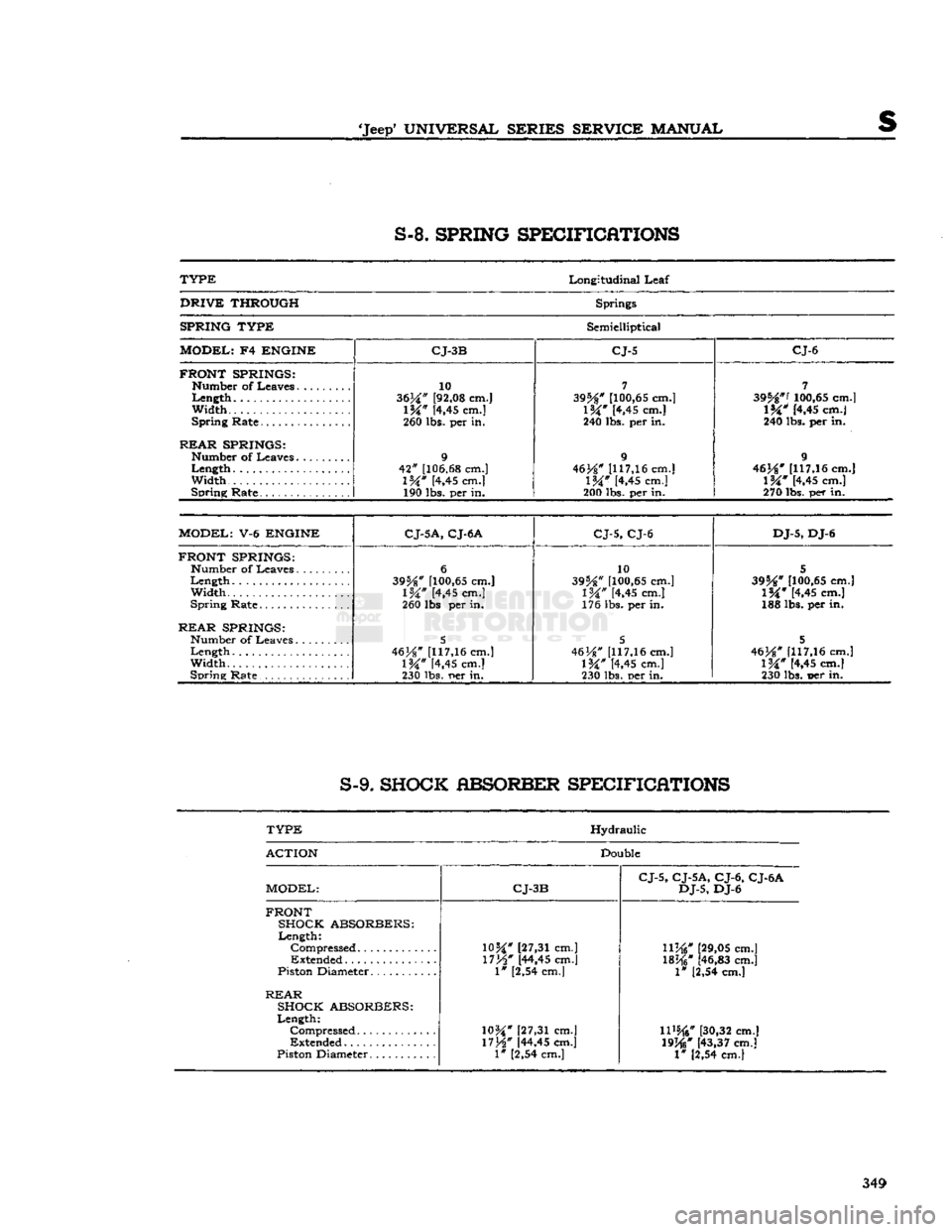
S-8.
SPRING SPECIFICATIONS
TYPE
Longitudinal
Leaf
DRIVE
THROUGH
Springs
SPRING TYPE
Semielliptical
MODEL;
F4
ENGINE CJ-3B CJ-5 CJ-6
FRONT SPRINGS:
Width...
REAR
SPRINGS:
Width
Spring
Rate
10
3634" [92,08 cm.]
\W
[4,45 cm.]
260 lbs. per in.
9
42"
[106.68 cm.]
l%"
[4,45 cm.] 190 lbs. per in.
7
395**
[100,65 cm.]
1&"
[4,45 cm.]
240 lbs. per in.
9
46J*#
[117,16 cm.]
IW
[4,45 cm.]
200 lbs. per in.
7
395*"'
100,65 cm.]
l%"
[4.45 cm.]
240 lbs. per in.
9
46}*"
1117,16 cm.]
l%"
[4,45 cm.]
270
lbs.
per in.
MODEL:
V-6
ENGINE
C
J-5A, CJ-6 A
CJ-5, CJ-6 DJ-5,
DJ-6
FRONT SPRINGS:
Number
of
Leaves
Width.....
Spring
Rate
REAR
SPRINGS:
Width
Spring
Rate
6
395*"
[100,65 cm.]
1%"
[4,45 cm.]
260 lbs per in.
5
46H"
[117,16 cm.]
\W
K,45
cm.]
230 lbs.
r»er
in. 10
39%"
[100,65 cm.]
IW
[4,45 cm.]
176 lbs. per in.
5
46
H"
[117,16 cm.]
IW
[4,45 cm.]
230 lbs. per in.
5
395**
[100,65 cm.]
1%"
[4,45 cm.]
188 lbs. per in.
5
463*"
[117,16 cm.]
1%"
[4,45 cm.]
230 lbs. t>er in.
S-9.
SHOCK ABSORBER SPECIFICATIONS
TYPE
Hydraulic
ACTION
Double
MODEL:
CJ-3B CJ-5, CJ-5A, CJ-6, CJ-6A
DJ-5,
DJ-6
FRONT SHOCK ABSORBERS:
Length:
"
[27,31 cm.]
Compressed
"
[27,31 cm.]
llj*i"
[29,05 cm.]
Extended
*
[44,45 cm.]
1%W
[46,83 cm.]
Piston Diameter
I" [2,54 cm.]
1* [2,54 cm.]
REAR
SHOCK ABSORBERS:
Length:
Compressed
10H
[27,31 cm.]
11%*
[30,32 cm.]
Extended
17H"
[44,45 cm.]
19j*j"
[43,37 cm.]
Piston Diameter
1"
[2,54 cm.] 1" [2,54 cm.]
349
Page 357 of 376
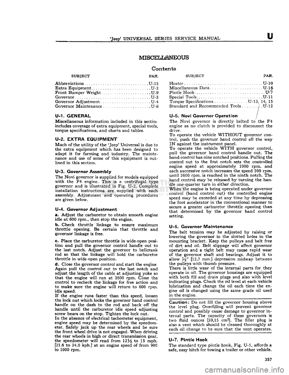
'Jeep'
UNIVERSAL SERIES SERVICE
MANUAL
u
MISCEIiLaNEOUS
Contents
SUBJECT
PAR.
Abbreviations
U-15
Extra
Equipment U-2
Front
Bumper Weight U-9
Governor
U-3
Governor
Adjustment U-4
Governor
Maintenance. U-6
U-1. GENERAL
Miscellaneous information included in this sectioi
includes coverage of extra equipment, special
tools,
torque specifications, and charts and tables.
U-2. EXTRA
EQUIPMENT
Much
of the utility of the
*
Jeep*
Universal
is due to
the extra equipment which has been designed to adapt it for farming and industry. The mainte
nance and use of
some
of this equipment is out
lined
in this section.
U-3.
Governor Assembly
The
Novi governor is supplied for models equipped
with
the F4 engine.
This
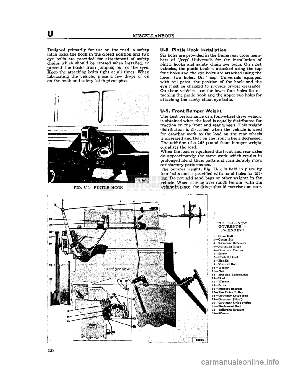
is a centrifugal type governor and is illustrated in Fig. U-2. Complete
installation
instructions are supplied with each
assembly. Adjustment and operating procedures
are
given below.
U-4.
Governor Adjustment
a.
Adjust the carburetor to obtain smooth
engine
idle at 600 rpm., then
stop
the engine.
b.
Check
throttle linkage to ensure maximum
throttle opening. Be certain that throttle and
governor linkage is free.
c.
Place the carburetor throttle in wide-open posi tion and
pull
the governor control handle out to
the last notch. Adjust the governor to bellcrank
rod
so that the linkage
will
hold the carburetor
throttle in wide-open position.
d.
Close the governor control and start the
engine
Again
pull
the control out to the last notch and
adjust
the length of the cable at adjusting yoke so
that the
engine
will
run at
2600
rpm. Close the
control
to recheck the linkage for free action and
to make sure the
engine
will
return to 600 rpm.
idle speed.
If
the
engine
runs faster than this speed,
loosen
the lock nut which locks the governor hand control
handle on the dash to the rod and back off the
handle until the carburetor idle speed adjusting
screw
bears on the stop. Tighten the lock nut.
In
the absence of electrical tachometer equipment,
engine
speed may be determined by the speedom
eter. Safely
jack
up the
rear
wheels and be sure the front wheel drive is not
engaged.
When driving
the
rear
wheels in high or direct transmission gear,
the
speedometer
will
read from 13j^ to 15 mph. [21.6 to 24.0 kph.] at an
engine
speed of from 900
to 1000 rpm.
SUBJECT
PAR.
Heater
U-10 Miscellaneous Data U-16
Pintle
Hook 1X7
Special
Tools. U-ll
Torque
Specifications U-13, 14, 15
Standard
and Recommended Tools
j.
.U-12
U-5.
Novi Governor Operation /
The
Novi governor is directly belted to the F4
engine
as no clutch is provided to disconnect the
drive.
To
operate the vehicle
WITHOUT
governor con
trol,
push the governor hand control all the way
IN
against the instrument panel.
To
operate the vehicle
WITH
governor control,
pull
the governor hand control handle out. The
hand
control has nine notched positions. Pulling the
control
out to the first notch
sets
the controlled
engine
speed at approximately 1000 rpm. and each successive notch increases the speed 200 rpm.
until
2600
rpm. is reached in the ninth notch. The
hand
control may be released by turning the han dle one-quarter
turn
in either direction.
When
the
engine
is being operated under governor
control
(hand control out) the controlled
engine
speed may be
exceeded
at any time by depressing
the
foot
accelerator in the conventional manner to
secure a greater carburetor throttle opening than
that determined by the governor hand control
setting.
U-6.
Governor Maintenance
The
belt tension may be adjusted by raising or
lowering the governor in the slotted
holes
in the mounting bracket. Keep the pulleys and belt free
of
dirt
and oil. Belt slippage
will
affect governor
operation and a tight belt may cause
rapid
wear
of the governor shaft and bearings. Adjust it to
allow Yi' [12,7 mm.] depression midway
between
the pulleys with thumb pressure.
There
is little wear of the internal parts for they
operate in oil. The governor housings are equipped
with
both
fill
and
drain
plugs and also with level
indicating
plugs.
Check
the oil level at each vehicle
lubrication
and change the oil each time the en
gine
oil is changed using the same grade oil used
in
the engine.
Caution:
Do not
fill
the governor housing above
the level plug. Overfilling
will
prevent governor
control
and possibly cause damage to governor in
ternal
parts. The capacity of
these
governors is two fluid ounces [59,15 cm3]. The filler plug is
also a vent which should be cleaned thoroughly at
each oil change to be sure that the vent operates.
U-7.
Pintle Hook
The
standard type pintle hook, Fig. U-1, affords a
safe, easy hitch for towing a
trailer
or other vehicle. 357
Page 358 of 376
u
MISCELLANEOUS
Designed primarily for use on the road, a safety
latch
locks the hook in the closed position and two
eye
bolts
are provided for attachment of safety chains which should be crossed when installed, to
prevent the hooks from jumping out of the
eyes.
Keep
the attaching
bolts
tight at all times. When
lubricating
the vehicle, place a few drops of oil on the hook and safety latch pivot pins.
FIG.
U-l—PINTLE HOOK
U-8.
Pintle Hook Installation
Six
holes
are provided in the frame
rear
cross mem
bers of 'Jeep* Universals for the installation of
pintle hooks and safety chain eye bolts. On most vehicles, the pintle hook is attached using the top
four
holes
and the eye
bolts
are attached using the
lower two holes. On 'Jeep* Universals equipped
with
tail
gates,
the position of the hook and the eye must be changed to provide proper clearance.
On
these
vehicles, use the lower four
holes
for attaching the pintle hook and the upper two
holes
for
attaching the safety chain eye bolts.
U-9.
Front
Bumper
Weight
The
best
performance of a four-wheel drive vehicle
is obtained when the load is equally distributed for
traction
on the front and
rear
wheels.
This
weight
distribution is disturbed when the vehicle is used
for drawbar work as the load on the
rear
wheels is increased and that on the front wheels decreased.
The
addition of a 265 pound front bumper weight
equalizes the load.
When
the load is equalized the front and
rear
axles
do approximately the same work which results in
prolonged life of
these
parts and considerably more
satisfactory performance.
The
bumper weight, Fig. U-3, is held in place by
four
bolts
and is provided with hand
holes
for lift
ing.
Do not add sand
bags
or other
weights
in the vehicle. When driving over rough
terrain,
with the
weight in place, the driver should exercise due care.
FIG.
U-2—NOVI
GOVERNOR
— F4 ENGINE
1—
Pivot
Bolt
2—
Cotter
Pin
3—
Governor
Beilcrank
4—
Adjusting
Block
5—
Governor
Control
6—
Screw
7—
Control
Bezel
8—
Handle
9—
Vertical
Rod
10—Washer
11
—Nut
12— Nut
and
Lockwasher
13—
Stud
14—
Washer
15—
Screw
16—
Support
Bracket
17—
Fan
Drive
Pulley
18—
Governor
Drive
Belt
19—
Governor
(Novi)
20—
Governor
Drive
Pulley
21—
Horizontal
Rod
22—
Beilcrank
Bracket
23—
Washer
358