engine JEEP CJ 1953 Service Manual
[x] Cancel search | Manufacturer: JEEP, Model Year: 1953, Model line: CJ, Model: JEEP CJ 1953Pages: 376, PDF Size: 19.96 MB
Page 208 of 376
H
ELECTRICAL
SYSTEM
sibility
of the cable shorting at the
engine
or frame.
Remove nut and lock washer securing the ignition
wire
to the solenoid
post
and remove the two screws and lock washers securing the solenoid to
the starter frame. Remove the switch,
b.
To install the solenoid switch reverse the re
moval
procedure given above.
H-10S.
STARTING MOTOR
—
DELCO
DAUNTLESS
V-6
ENGINE
Refer
to Fig. H-45.
The
starting motor used on the Dauntless V-6 en
gine
has an integral solenoid switch and enclosed
shift lever which first shifts the overrunning clutch
pinion into
engagement
with the ring gear on the
flywheel of the
engine
and then
closes
the electrical
circuit
to cause
engine
cranking. When the
engine
starts,
the overrunning clutch
disengages
to pre vent transfer of
engine
speed to the starting motor.
Note:
Should a service replacement starter motor
be required the factory recommends replacement
with
original equipment parts; however, should the need arise an existing starter motor (Delco or
Prestolite) could be replaced with the current
Delco-Remy
starter, model 1108375, with the
following modifications to the wiring harness. If
the existing starter motor wiring harness
does
not
provide a 12 ga. purple conduit wire, (connects the ignition switch to the starter motor) then a 12 ga.
purple
conduit wire 70 inches long, must be in
stalled.
Should the existing starter motor wiring
harness
contain a 16 ga. light blue conduit wire, (connects the ignition switch and starter motor)
bend this wire back and tape out of the way.
H-109.
Starting Motor Disassembly
a.
Before removing the starting motor from the
engine, disconnect leads and cover battery lead
terminal
with piece of
hose
or tape to prevent
short circuiting.
Note
locations of wiring connec
tions to assure proper reconnection. Remove the cap screw that secures the starting motor to the
angle bracket on the side of the engine. Remove
the two cap screws that secure the drive end of
the starting motor to the cylinder block; remove
the starting motor.
b.
Remove terminal nut and disconnect field lead,
which
passes through grommet at top of motor,
from
motor terminal of solenoid. Remove two
thru
bolts
from motor. Remove commutator end frame
and
field frame assembly from solenoid and drive assembly.
e.
Pull
out pivot pins of brush holders and remove each of two brush holder and spring assemblies
from
field housing. Remove screws which attach
brushes and leads to holders.
d.
Remove armature and drive assembly from
drive
housing. Remove thrust collar from pinion
end of armature shaft. Remove leather thrust
washer
from
opposite
end of shaft.
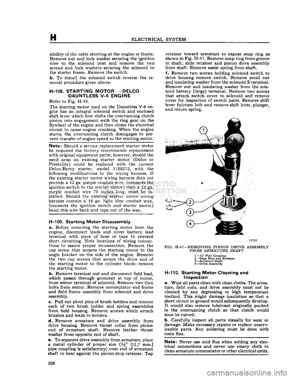
e. To separate drive assembly from
armature,
place
a
metal cylinder of proper size (J^" [12,7 mm.]
pipe coupling is satisfactory) over end of armature
shaft to bear against the pinion
stop
retainer. Tap
retainer
toward armature to
expose
snap ring as
shown in
Fig.
H-47. Remove snap ring from
groove
in
shaft; slide retainer and pinion drive assembly
from
shaft. Remove assist spring from shaft,
f.
Remove two screws holding solenoid switch to
drive
housing remove switch. Remove small nut
and
insulating washer from the solenoid S terminal.
Remove nut and insulating washer from the
sole
noid battery (large) terminal. Remove two screws that attach switch cover to solenoid and remove cover for inspection of switch parts. Remove shift
lever fulcrum bolt and remove shift lever, plunger,
and
return spring.
12765
FIG.
H-47—REMOVING PINION
DRIVE
ASSEMBLY
FROM
ARMATURE SHAFT
1— XA ' Pipe Coupling
2—
Snap
Ring
and Retainer
3—
Armature
Shaft
4—
Drive
Assembly
H-110.
Starting
Motor
Cleaning and
Inspection
a.
Wipe all parts clean with clean cloths. The
arma
ture,
field coils, and drive assembly must not be
cleaned by any degreasing or high temperature
method.
This
might damage insulation so that a
short
circuit
or ground would subsequently develop.
It
would also remove lubricant originally packed
in
the overrunning clutch so that clutch would
soon
be ruined.
b.
Carefully
inspect all parts visually for wear or
damage. Make necessary repairs or replace unserv
iceable parts. Any soldering must be
done
with
rosin
flux.
Note:
Never use acid flux when solding any elec
trical
connections and never use emery cloth to
clean
armature
commutator or other
electrical
units. 208
Page 212 of 376
H
ELECTRICAL
SYSTEM
H-124. Testing Indicators and Gauges
Two
gauges
(fuel and temperature) and two in dicators (oil pressure and battery charge) that are
located in the instrument cluster are electrically operated.
The
fuel
gauge
is connected by a single wire to a
float-and-slide-rheostat sending unit in the fuel
tank.
The
temperature
gauge
is connected by a single
wire
to a resistance-type sending unit mounted on the engine.
The
battery charge indicator operates when there
is a difference in potential
between
the generator
and
the battery
.The
battery charge indicator lights
when the generator is not charging the battery. The
indicator
light
goes
out when the generator
begins
to charge the battery.
The
oil pressure indicator is connected by a single
wire
to a diaphragm switch located on the engine.
When
engine
oil pressure is low or zero and the
ignition switch is on, the oil pressure indicator
will
light. When
engine
speed is increased slightly above idle speed, raising the oil pressure to approximately 6 psi. [0,2 kg-cm2], the diaphragm switch
will
open the circuit and the indicator light
will
go out.
A
voltage
regulator maintains a constant
voltage
to the
gauges
in normal operation. On early vehicles,
this
voltage
regulator was mounted on the
rear
of
the instrument cluster. On current vehicles, the
voltage
regulator is integral with the fuel
gauge.
Should
trouble
develop
in the
gauges,
first check the regulator (fuel
gauge
on current production vehicle). If the
voltage
to the regulator is below 10 volts system low
gauge
readings
will
result.
Voltage in
excess
of 16 volts
will
not affect
gauge
readings but may result in premature wear of the
regulator contacts. If the
voltage
to the regulator is
within
the above limits, check the electrical con nections to the regulator (or fuel gauge), especially
the ground connection. If the readings of all the
gauges
is too high, or they all read too low, replace
the regulator (or fuel gauge).
If
the temperature
gauge
or heat indicator in the
instrument cluster have failed, the cause may
originate from the jumper bar shorting out against the instrument case.
Check
the jumper bar
between
the temperature
gauge
and heat indicator at the
rear
of the instrument case. On later production vehicles, the jumper bar is covered with an in
sulating
sleeve
to protect it from shorting out
against the instrument case. If the jumper bar
does
not have this
sleeve,
either install one or
wrap
the bar with plastic electrical tape to
half
an
inch [12,7 mm.] from each end. When installing the jumper bar, be sure the curved
segment
is
closest to the fuel
gauge.
Should
only one of the two
gauges
register incor
rectly,
check the lead wire from the
gauge
to the
sending unit for shorts or open connections. Next disconnect the
gauge
from the sending unit, and
connect the
gauge
to a new fuel tank sending unit
which
has been grounded to the vehicle.
If
the
gauge
registers incorrectly when operating the new unit,
replace the
gauge;
if correctly, replace the sending
unit.
Should
a new fuel tank unit not be available for testing, use a 12-volt
test
light in its place. When
the
gauge
is operating correctly, the pointer
will
move
approximately three-quarters across the
dial.
On
some
vehicles, the temperature
gauge
may
register on or
close
to the H (hot)
mark
when
coolant temperature is
190°F.
to
200°F.
[88°C.
a
93°C.].
In such cases, a 25-ohm,
1-watt
resistor
may be installed on the temperature
gauge
which
will
place the pointer just beyond the center
mark
at a coolant temperature of
190°F.
to
200°F.
Install
the resistor
between
the two terminals on the back
of the
gauge.
Insulate the
exposed
leads of the resistor with electrical tape.
If
the oil pressure indicator
does
not indicate cor
rectly,
first check the light bulb. Next check all
connections and lead wires. If, after all possible
defects
are corrected, the indicator light
does
not go on and off properly, then the diaphragm type
switch in the cylinder block should be replaced.
H-12S.
LIGHTING SYSTEM The
wiring of the lighting systems is shown in
the wiring diagrams, which indicate the various units in relation to their positions in the vehicle.
The
wires in the various circuits are of different
colors or are marked by tracers to aid when check
ing individual circuits.
The
lighting circuits of all models are protected by
an
overload circuit breaker mounted on the back of the main light switch and no replaceable fuse is
required.
The
upper and lower headlight beams are con
trolled by a
foot
switch located on the toe board
to the left of the clutch pedal.
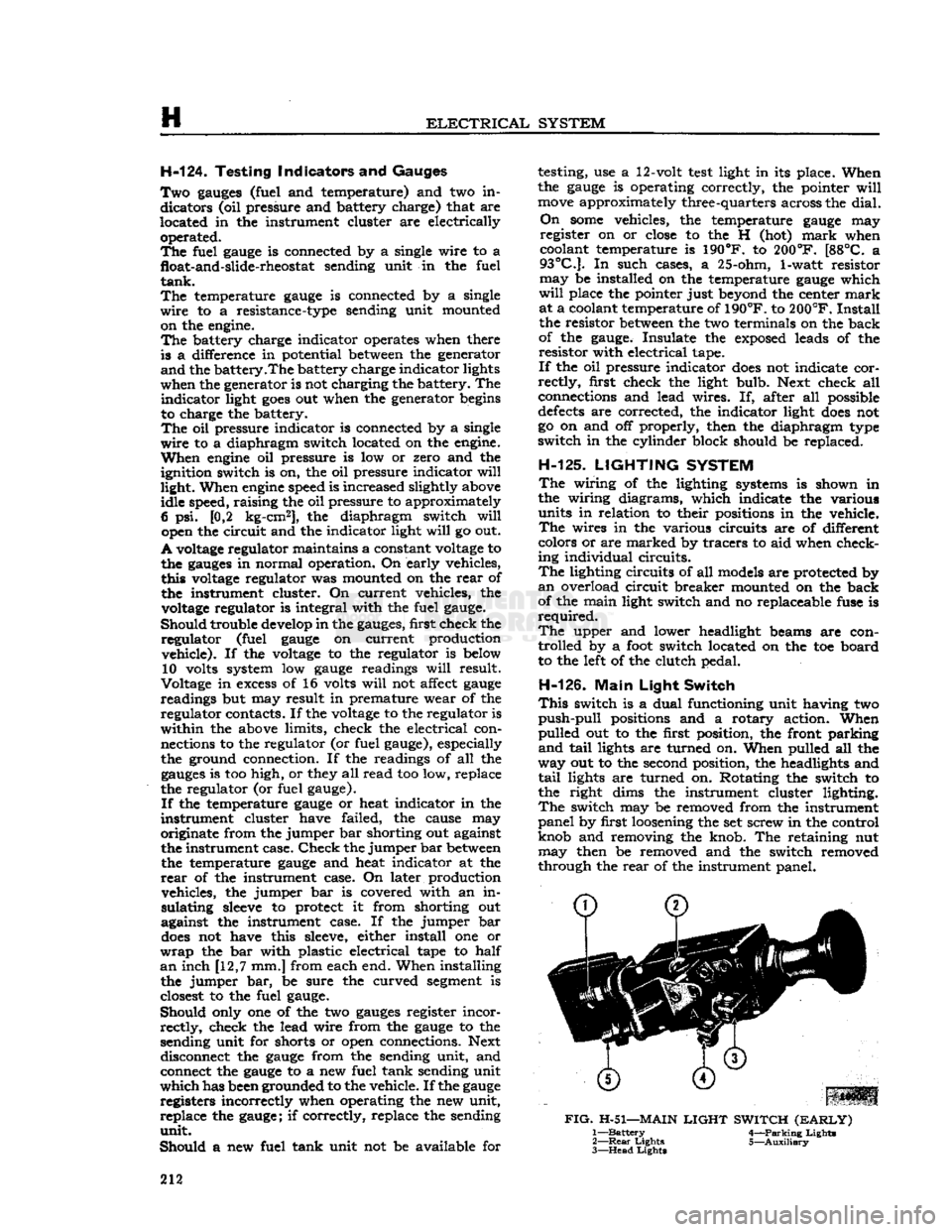
H-126.
Main
Light
Switch
This
switch is a dual functioning unit having two
push-pull
positions and a rotary action. When
pulled out to the first position, the front parking
and
tail
lights are turned on. When pulled all the
way out to the second position, the headlights and
tail
lights are turned on. Rotating the switch to
the right dims the instrument cluster lighting.
The
switch may be removed from the instrument
panel by first loosening the set screw in the control
knob and removing the knob. The retaining nut may then be removed and the switch removed
through the
rear
of the instrument panel.
FIG.
H-51—MAIN
LIGHT
SWITCH
(EARLY)
1—
Battery
4—Parking Lights
2—
Rear
Lights 5—Auxiliary
3—
Head
Lights
212
Page 217 of 376
'Jeep'
UNIVERSAL
SERIES
SERVICE
MANUAL
H
cuit
lights,
the
signal switch
is
inoperative
and
must
be
replaced.
H-139.
Hazard
Warning Lights
All
current production vehicles
are
equipped with
a
four-way flasher warning system.
The
control switch
is
located
on the
instrument panel left
of
the steering column.
With
the
switch pulled
out,
the
two
front and
two
rear
turn
signal lights flash
on and
off
simultaneously,
as do
both
turn
signal
indicator
lights
on the
instrument clusters.
H-140.
Marker
Lights and Reflector Assembly
The
marker
lights
and
reflector assemblies
on
current
production vehicles
are
mounted
on the
side
of
the front fender and
on the
side
of
the
rear
quarter
panel.
The
spare wheel also mounts
a
marker
light. Some earlier production vehicles have
reflex reflectors mounted on the side of the hood and
on
the
side
of
the
rear
quarter panel. determine
if
dash wiper switch or wiring
is at
fault,
disconnect wiring harness from wiper motor
and
try
operating wiper independently
of
dash switch.
If
still
inoperative
see
procedure under
Par.
H-145.
b. Wiper
will
not
shut
off
— Determine
if
wiper
has both
low
and high speeds, slow speed only,
or
high speed only.
It is
important that
the
wiper
operates
at low
speed during parking cycle.
Dis
connect wiring harness from wiper motor
and try
operating wiper independently
of
dash switch.
If
wiper
shuts
off
correctly with
crank
arm
in
park
position and wiper has both speeds, check
the
lead
between
terminal
and
dash switch ground
and
check
for
defective dash switch.
If
wiper shuts
off
correctly,
but has
high speed only, check lead
be
tween wiper terminal and dash switch
for an
open
circuit
and check
for
defective dash switch.
If
still
inoperative,
see
Par. H-145.
c. Wiper
has
only fast speed.
Check
for
defective dash switch
or
open lead
between
terminal
and
dash switch.
H-141.
Windshield Wiper System
Early
production vehicles equipped with
the
Dauntless V-6
engine
have
two
single speed wind
shield wiper motors mounted above
the
windshield inside
the
vehicle. The wiper motors
are
operated
and
controlled
by a
switch located
on the
instru
ment panel.
Current
production vehicles with stationary wind
shield have
a
two-speed
electric windshield wiper motor mounted below
the
windshield outside
the
vehicle on the driver's side. The wiper motor switch is located
on the
instrument panel
to the
left
of
the steering column.
H-142.
Two-Speed Wiper Motor
The
two-speed
electric wiper motor
is
operated and
controlled
by a
turn
type, three poled, dash switch,
containing
a 6
amp. circuit breaker.
Current
flow
is directed from
the
battery through
the
ignition
switch
to the
wiper dash switch assembly
to the
two-speed
wiper motor, which passes current from the designated motor brush (high,
low or
park)
to
the armature circuit
to
ground.
H-143.
Troubleshooting Procedure
Troubleshooting procedures
are
divided into
two
categories: wiper troubleshooting
in
vehicle; wiper
troubleshooting
on
bench.
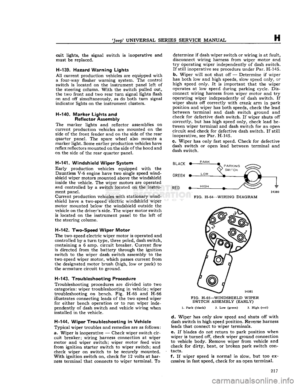
Fig. H-65 and H-66
illustrates connecting leads
of the
two-speed
wiper for either bench operation
or to run
wiper inde
pendently
of
dash switch and vehicle wiring when
installed
in the
vehicle.
H-144. Wiper Troubleshooting
in
Vehicle
Typical
wiper troubles and remedies are
as
follows
:
a.
Wiper
is
inoperative
—
Check
wiper switch
cir
cuit
breaker; wiring harness connection
at
wiper
motor
and
wiper switch; wiper motor
feed
wire
from
ignition starter switch
to
wiper switch;
and
check wiper
on
switch
to be
securely mounted.
With
ignition switch
on,
check
for 12
volts
at
har
ness
terminal that connects
to
wiper terminal.
To
BLACK
PARK
GREEN *-
RED m~
LOW
PARKING
<^^>
SWITCH
V^-O*'
HIGH
FIG.
H-64—WIRING
DIAGRAM
FIG.
H-65—WINDSHIELD
WIPER
SWITCH
ASSEMBLY
(EARLY)
1.
Park
(black)
2. Low (green)
3.
High (red)
d.
Wiper
has
only slow speed
and
shuts
off
with
dash switch in high speed position. Reverse harness
leads that connect
to
wiper terminals.
e. If
blades
do not
return
to
park
position when
wiper
is
turned
off,
check wiper ground connection
to vehicle body. Remove wiper from vehicle
and
check
for
dirty, bent,
or
broken
park
switch con
tacts.
f.
If
wiper speed
is
normal
in
slow,
but too ex
cessive
in
fast speed, check for an open terminal. 217
Page 220 of 376
H
ELECTRICAL
SYSTEM H-15L SERVICE
DIAGNOSIS
SYMPTOMS
Battery
Discha
rged: Shorted
Cell
in Battery......... Short in Wiring..
•
Generator Not Charging ,
Loose or Dirty Terminals
Excessive Use of Starter Excessive Use of Lights...... Insufficient Driving.........
Low
Regulator
Setting.......
Stuck
Cut-out in Regulator. ..
Low
Electrolyte
Level
in Cells
Alternator:
FAILS
TO
CHARGE:
Belt Loose Open or High Resistance in
Charging
or Ground Return
Circuit
or Battery Connections............
Excessively Worn, Open, or
Defective
Brushes.
Open Isolation
Diode.
Open Rotor (Field
Coil)
LOW
OR
UNSTEADY
CHARGING RATE:
Belt Loose.... Intermittent or High Resistance
Charging
or Ground Return
Circuit
or Battery Connections
Excessively Worn, Sticky, or Intermittent Brushes
Shorted or Open Rectifier
Diode
Grounded
or Shorted
Turns
in Rotor (Field
Coil)
Open,
Grounded, or Shorted
Turns
in
Stator
EXCESSIVE
CHARGE RATE:
Loose Connections on Alternator...........
Faulty
Regulator
NOISY
ALTERNATOR:
Defective
or Badly Worn Belt
Misaligned Belt or Pulley
Loose Pulley
Worn
Bearings.
Shorted Rectifiers
Generator:
Low
Charging Rate—
Dirty
Commutator
Poor Brush Contact.
................
Regulator Improperly Adjusted.......
High
Resistance in Charging
Circuit...
Ground
Strap Engine to Frame Broken
Loose or Dirty Terminals Slipping Generator Belt
Worn
Out Brushes
Weak
Brush Spring Tension..........
Out
of Round Commutator
PROBABLE REMEDY
Replace Battery
Check
Wiring
Circuit
Inspect Generator and Fan Belt
Clean
and Tighten
Tune
Engine
Check
Battery
Recharge Battery
Correct
Setting
Correct
Add
Distilled Water
Tighten to
Specifications
Test
and Correct
Test
Brushes and Replace if Necessary
Test
and Replace if Necessary
Test
and Replace if Necessary
Tighten to
Specifications
Test
and Correct
Test
and Replace if Necessary
Test
and Replace if Necessary
Test
and Replace if Necessary
Test
and Replace if Necessary
Check
and Correct
Check
and Correct
Replace
Align,
Replace Parts as Necessary Tighten Replace Bearings as Necessary
Test
and Replace as Necessary
Clean
Commutator
Repair
or Install New Brushes
Adjust
Clean
and Tighten Terminals Replace
Clean
and Tighten
Adjust
Belt
Install
New Brushes
Replace
Repair
220
Page 221 of 376
'Jeep*
UNIVERSAL
SERIES SERVICE
MANUAL
H
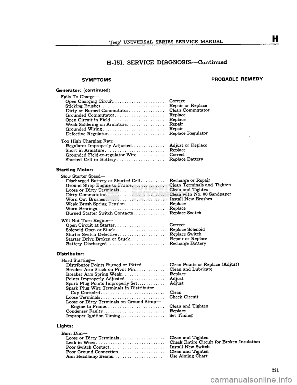
H-151.
SERVICE
DIAGNOSIS—Continued
SYMPTOMS PROBABLE
REMEDY
Generator:
(continued)
Fails
To Charge-Open Charging Circuit Correct
Sticking Brushes Repair or Replace
Dirty
or Burned Commutator ... Clean Commutator
Grounded Commutator Replace
Open Circuit in Field Replace
Weak Soldering on Armature. . . Repair Grounded Wiring Repair
Defective
Regulator. .. Replace Regulator
Too High Charging Rate— Regulator Improperly Adjusted Adjust or Replace
Short in Armature Replace Grounded Field-to-regulator Wire Correct
Shorted
Cell
in Battery... Replace Battery
Starting
Motor: Slow Starter Speed— Discharged Battery or Shorted
Cell
Recharge or Repair
Ground
Strap Engine to Frame. Clean Terminals and Tighten
Loose or Dirty Terminals Clean and Tighten
Dirty
Commutator Clean with No. 00 Sandpaper
Worn
Out Brushes Install New Brushes
Weak Brush Spring Tension Replace
Worn
Bearings Replace Burned Starter Switch Contacts Replace Switch
Will
Not
Turn
Engine— Open Circuit at Starter Correct
Solenoid
Open or Stuck Replace
Solenoid
Starter Switch
Defective
Replace Switch
Starter Drive Broken or Stuck. Repair or Replace
Battery Discharged Recharge Battery
Distributor:
Hard
Starting— Distributor
Points
Burned or Pitted Clean
Points
or Replace (Adjust)
Breaker
Arm Stuck on Pivot Pin...... . ... . . . Clean and Lubricate
Breaker
Arm Spring Weak Replace
Points
Improperly Adjusted Adjust
Spark
Plug
Points
Improperly Set Adjust
Spark
Plug Wire Terminals in Distributor
Cap
Corroded Clean
Loose Terminals Check Circuit
Loose or Dirty Terminals on Ground Strap— Engine to Frame. Clean and Tighten
Condenser Faulty Replace Improper Ignition Timing Set Timing
Lights:
Burn
Dim— Loose or Dirty Terminals....... ........ Clean and Tighten
Leak
in Wires. Check Entire Circuit for Broken Insulation
Poor Switch Contact Install New Switch Poor Ground Connection Clean and Tighten
Aim
Headlamp Beams. Use Aiming
Chart
221
Page 223 of 376
'Jeep'
UNIVERSAL SERIES SERVICE
MANUAL
H
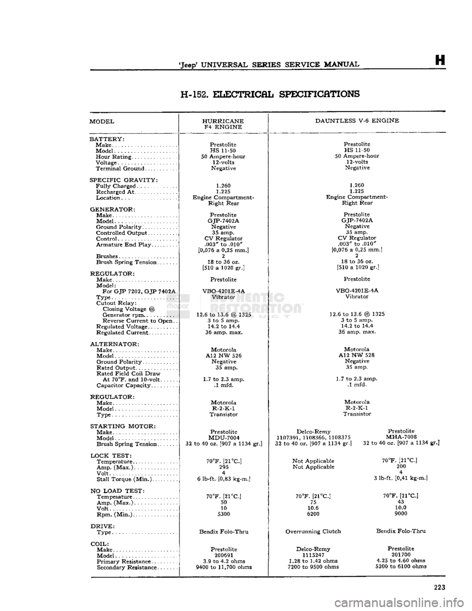
H-152.
ELECTRICAL
SPECIFICATIONS
MODEL HURRICANE
F4 ENGINE DAUNTLESS
V-6
ENGINE
BATTERY:
Make
Model Hour Rating.
Voltage
Terminal
Ground
SPECIFIC
GRAVITY:
Fully
Charged
Recharged At
Location
GENERATOR:
Make.
Model
Ground
Polarity
Controlled Output
Control
Armature End Play
Brushes
Brush
Spring Tension
REGULATOR:
Make
Model:
For
GJP
7202,
GJP
7402A
Type
Cutout Relay: Closing
Voltage
@
Generator rpm..........
Reverse Current to Open.
Regulated
Voltage
Regulated Current
ALTERNATOR:
Make
Model
Ground
Polarity
Rated Output
Rated Field
Coil
Draw
At
70°F.
and
10-volt
Capacitor Capacity
REGULATOR:
Make
Model
Type
STARTING
MOTOR:
Make
Model
Brush
Spring Tension
LOCK
TEST:
Temperature
Amp.
(Max.)
Volt
Stall
Torque (Min.)
NO LOAD TEST:
Tempesature
Amp.
(Max.)
Volt
Rpm.
(Min.)
DRIVE:
Type
COIL:
Make.
Model
Primary
Resistance Secondary Resistance
Prestolite
HS
11-50
50 Ampere-hour
12-volts
Negative
1.260
1.225
Engine Compartment- Right Rear
Prestolite
GJP-7402A
Negative
35 amp.
CV
Regulator .003" to .010"
[0,076
a 0,25 mm.] 2
18 to 36 oz.
[510 a 1020 gr.]
Prestolite
VBO-4201E-4A
Vibrator
12.6 to 13.6 @ 1325 3 to 5 amp. 14.2 to 14.4
36 amp. max.
Motorola
A12 NW 526
Negative
35 amp.
1.7 to 2.3 amp. .1 mfd.
Motorola
R-2-K-1
Transistor
Prestolite
MDU-7004
32 to 40 oz. [907 a 1134 gr.]
70°F.
[21°C] 295 4
6 lb-ft. [0,83
kg-m.]
70°F.
[21°C.;
50
10
5300
Bendix Folo-Thru
Prestolite
200691
3.9 to 4.2
ohms
9400
to
11,700
ohms
Prestolite
HS
11-50
50 Ampere-hour
12-volts
Negative
1.260
1.225
Engine Compartment- Right Rear
Prestolite
GJP-7402A
Negative
35 amp.
CV
Regulator .003" to .010"
[0,076
a 0,25 mm.] 2
18 to 36 oz.
[510 a 1020 gr.]
Prestolite
VBO-4201E-4A
Vibrator
12.6 to 13.6 @ 1325 3 to 5 amp. 14.2 to 14.4
36 amp. max.
Motorola
A12 NW 528
Negative
35 amp.
1.7 to 2.3 amp. .1 mfd.
Motorola
R-2-K-1
Transistor
Delco-Remy
1107391,
1108366,
1108375
32 to 40 oz. [907 a 1134 gr.]
Not Applicable Not Applicable
70°F.
[21°C] 75
10.6
6200
Overrunning Clutch Delco-Remy
1115247
1.28 to 1.42
ohms
7200
to
9500
ohms
Prestolite
MHA-7008
32 to 40 oz. [907 a 1134 gr.]
70°F.
[21°C] 200 4
3 lb-ft. [0,41
kg-m.]
70°F.
[21°C] 43
10.0
9000
Bendix Folo-Thru
Prestolite
201700
4.25 to 4.60
ohms
5200
to 6100
ohms
223
Page 224 of 376
H
ELECTRICAL
SYSTEM
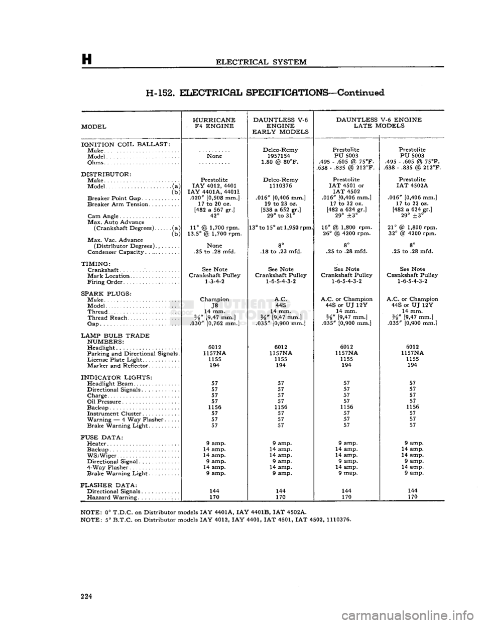
H-152.
ELECTRICAL
SPECIFICATIONS—Continued
HURRICANE DAUNTLESS
V-6
DAUNTLESS
V-6 ENGINE
MODEL -
F4
ENGINE
ENGINE
LATE
MODELS
EARLY
MODELS
IGNITION
COIL
BALLAST
]Make Delco-Remy
Prestolite Prestolite
Model
None
1957154
PU
5003
PU
5003
Ohms • • 1.80 @
80°F.
.495 - .605 @
75°F.
.495 - .605 @
75°F.
1.80 @
80°F.
.638 - .835 @
212°F.
.638 - .835 @
212°F.
DISTRIBUTOR:
Prestolite Delco-Remy Prestolite Prestolite
Model
•
(a)
LAY
4012, 4401
1110376
I
AT
4501 or
IAT
4502A
(b)
I
AY
4401A, 44011
IAT
4502
Breaker
Point Gap (b)
.020"
[0,508
mm.] .016"
[0,406
mm.] .016"
[0,406
mm.]
.016"
[0,406
mm.]
Breaker
Arm Tension. ..... 17 to 20 oz.
19 to 23 oz. 17 to 22 oz. 17 to 22 oz.
[482 a 567 gr.] [538 a 652 gr.] [482 a 624 gr.]
[482 a 624 gr.]
42° 29°
to 31°
29°
±3°
29°
±3°
Max.
Auto Advance
(Crankshaft
Degrees) •(a)
11°
@ 1,700 rpm.
13°
to
15°
at 1,950 rpm.
16°
@ 1,800 rpm.
21°
(2 1,800 rpm.
(Crankshaft
Degrees)
(b)
13.5°
@ 1,700 rpm.
26°
@
4200
rpm.
32°
@
4200
rpm.
Max.
Vac. Advance go
(Distributor Degrees)., . .
None
8° 8°
go
Condenser Capacity. . .25 to .28 mfd. .18 to .23 mfd. .25 to .28 mfd. .25 to .28 mfd.
TIMING:
Crankshaft
See
Note
See
Note
See
Note
See
Note
Mark
Location............
Crankshaft
Pulley
Crankshaft
Pulley
Crankshaft
Pulley
Csankshaft
Pulley
Firing
Order
1-3-4-2
1-6-5-4-3-2
1-6-5-4-3-2 1-6-5-4-3-2
SPARK PLUGS:
Make
Champion
A.C. A.C.
or Champion
A.C.
or Champion
J8
44S
44S or UJ 12Y 44S or UJ 12Y
Thread
14 mm.
14 mm. 14 mm. 14 mm.
Thread
Reach
Vz"
[9,47 mm.]
%"
[9,47 mm.]
¥%"
[9,47 mm.]
V8" [9,47 mm.]
Gap
.030"
[0,762
mm.]
.035"
[0,900
mm.] .035"
[0,900
mm.] .035"
[0,900
mm.|
LAMP BULB TRADE
NUMBERS:
Headlight 6012
6012 6012 6012
Parking
and Directional Signals. 1157NA
1157NA 1157NA 1157NA
License
Plate Light........ 1155
1155 1155 1155
Marker
and Reflector 194
194 194 194
INDICATOR LIGHTS:
57 57 57 57
Directional Signals........ 57
57 57 57
Charge
57
57 57 57
57 57 57 57
1156 1156 1156 1156
Instrument Cluster 57 57 57 57
Warning
— 4 Way Flasher. . 57
57 57 57
Brake
Warning Light 57
57 57 57
FUSE
DATA:
Heater 9 amp. 9 amp. 9 amp. 9 amp.
Backup
14 amp. 14 amp. 14 amp. 14 amp.
WS/Wiper.
14 amp. 14 amp. 14 amp. 14 amp.
Directional Signal 9 amp. 9 amp. 9 amp. 9 amp.
4-Way Flasher 14 amp. 14 amp. 14 amp. 14 amp.
Brake
Warning Light 9 amp. 9 amp. 9 map. 9 amp.
FLASHER
DATA:
Directional Signals. 144
144 144 144
Hazzard
Warning. 170
170 170 170
NOTE:
0°
T.D.C.
on Distributor
models
IAY 4401A, IAY 4401B, IAT 4502A.
NOTE:
5°
B.T.C.
on Distributor
models
IAY 4012, IAY 4401, IAT 4501, IAT 4502,
1110376.
224
Page 225 of 376
'Jeep'
UNIVERSAL
SERIES SERVICE
MANUAL
CLUTCH
Contents
SUBJECT
PAR.
GENERAL
.1-1
Clutch
Maintenance 1-2
Clutch
Pedal Linkage and Adjustment.... 1-3
Pilot Bushing Inspection and
Replacement 1-8
CLUTCH
—HURRICANE
F4
ENGINE.
. . .1-4
Clutch
Removal. 1-5
Clutch
Pressure Plate and Disc Inspection.
.
1-6
Clutch
Pressure Plate Adjustment 1-7
Clutch
Installation 1-9
CLUTCH
—DAUNTLESS
V-6
ENGINE,
DIAPHRAGM
SPRING
TYPE
1-10
Clutch
Removal.
........
.1-11
Clutch
Inspection, Diaphragm Spring Type. . 1-12
Clutch
Installation 1-27
SUBJECT
PAR.
SERVICING COIL
SPRING
TYPE CLUTCH
. .1-13 Pressure Plate Adjustment. 1-14
Pressure Plate Disassembly. . . . . 1-15
Inspection of Parts 1-16 thru 1-20 Pressure Plate Reassembly. . . . .1-21 thru 1-23
Clutch
Lever Adjustment 1-24
Clutch
Fitxure . .1-26
CLUTCH
THROWOUT
RELEASE
BEARING
1-25
SERVICE
DIAGNOSIS
1-28
CLUTCH
SPECIFICATIONS
1-29
CLUTCH
ADJUSTING
FIXTURE
DATA
1-30
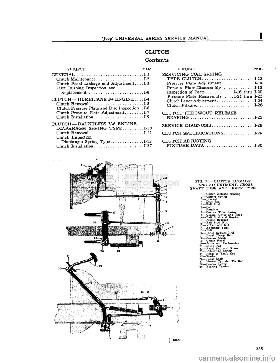
FIG.
I-1—CLUTCH
LINKAGE AND
ADJUSTMENT,
CROSS
SHAFT
TUBE
AND
LEVER
TYPE
1—
Clutch
Release Bearing
2—
Carrier
Spring
3—
Bracket
4— Dust Seal 5—
Ball
Stud 6—
Pad
7— Retainer
8—
Control
Tube Spring
9—
Control
Lever and Tube
10—
Ball
Stud and Bracket
11—
Frame
Bracket
12—
Ball
Stud Nut 13—
Yoke
Lock
Nut
14— Adjusting Yoke
15— Bolt
16— Pedal Release Rod
17— Pedal Clamp Bolt 18—
Control
Cable
19—
Clutch
Pedal
20— Screw and Lockwasher
21—
Draft
Pad 22— Pedal Pad and Shank
23— Retracting Spring
24— Pedal to Shaft Key 25— Washer
26— Pedal Shaft
27— Master Cylinder Tie Bar
28—
Control
Lever
29— Bearing
Carrier
10734
225
Page 226 of 376
![JEEP CJ 1953 Service Manual
I
CLUTCH 1-1.
GENERAL
The
clutch on current Jeep vehicles is either
Auburn
or Borg and Beck manufactured. Vehicles
equipped with F4-134
engines
have an
Auburn
9.25" [23,4 cm.] single JEEP CJ 1953 Service Manual
I
CLUTCH 1-1.
GENERAL
The
clutch on current Jeep vehicles is either
Auburn
or Borg and Beck manufactured. Vehicles
equipped with F4-134
engines
have an
Auburn
9.25" [23,4 cm.] single](/img/16/57040/w960_57040-225.png)
I
CLUTCH 1-1.
GENERAL
The
clutch on current 'Jeep' vehicles is either
Auburn
or Borg and Beck manufactured. Vehicles
equipped with F4-134
engines
have an
Auburn
9.25" [23,4 cm.] single plate dry-disc clutch. The
pressure plate has three coil pressure springs and
three levers or fingers.
The
V6-225
engine
is equipped with a 10.4" [26,4
cm.] Borg and Beck single plate dry-disc clutch.
The
pressure plate utilizes either a finger-type
diaphragm spring, or a coil
type
spring pressure plate for clutch release.
The
driven plates of all
models
are built with
vibra
tion damper springs and have two flexible facings
which
provide
smooth
engagement
of the
engine
power.
Early
'Jeep' vehicles equipped with a Dauntless
V-6
engine
use a 10.4" [26,4 cm.] single plate, dry-
disc clutch, incorporating a diaphram-type spring assembly.
The
clutch is of the centrifugal single dry disc
type
and
consists of the clutch disc, pressure plate and
the clutch release bearing.
The
clutch is actuated by a clutch pedal and a
series of mechanical linkage.
When
the clutch pedal is in the
engaged
position,
the clutch disc facings are clamped
between
the
friction surface of the
engine
flywheel and the face of the clutch pressure plate, thereby connect
ing
engine
power to the transmission. Depressing
the clutch pedal actuates the clutch release shaft
fork
which
moves
the clutch release bearing against
the clutch fingers.
This,
in
turn,
moves
the pressure
plate away from the clutch disc. Since the disc is splined to the transmission input shaft, the clutch
disc and transmission input shaft
will
stop
when
the clutch is disengaged, thereby disconnecting
engine
power from the transmission.
1-2.
Clutch
Maintenance
To
obtain normal life and satisfactory performance
from any clutch it must be correctly operated and
properly maintained. Two conditions which shorten
clutch life are continuous operation of the clutch
release bearing and clutch slippage.
The
clutch release bearing is
designed
for inter
mittent use. If run continuously the bearing
lubri
cant
will
become
exhausted causing the bearing to
become
dry, noisy, or
will
seize, resulting in clutch
finger or diaphragm wear. The clutch must be properly adjusted so that the release bearing is
free of the clutch fingers or diaphragm at all times,
except
when the clutch pedal is depressed.
Excessive
clutch slippage
often
occurs when the
vehicle is overloaded, the vehicle load is applied
too quickly, or when the pressure of the clutch fingers or diaphragm is only partially applied to the clutch plate.
Friction
between
the clutch facing
and
flywheel produces
excessive
heat causing
burned,
glazed and worn linings, resulting in shortened clutch life. Avoid clutch slippage under
heavy loads by using a lower gear or reducing the load.
1-3.
Clutch
Pedal
Linkage
and Adjustment
Adjust
the clutch pedal free travel whenever the clutch
does
not
disengage
properly, or when new
clutch parts are installed. Improper adjustment of
the clutch pedal free travel is one of the
most
fre
quent causes of clutch failure and can be a con tributing factor in
some
transmission failures.
As
the clutch facings wear the free travel of the clutch pedal diminishes. When sufficient wear oc
curs
the pedal clearance must be adjusted.
Two
types
of clutch linkage have
been
used on Jeep vehicles, a cross shaft
tube
and lever
type
shown in Fig. 1-1, and a clutch control cable
type
shown in Fig. 1-2. The clutch pedal adjustment
procedures for both
type
linkages are as follows.
•
Cross
Shaft
Lever
and Tube Type
Refer
to Fig. 1-1.
Note:
Two different
Clutch
Control
Lever
and
Tube
Assemblies have
been
installed on 'Jeep*
Universal
vehicles equipped with a V-6
engine
and
T14A
transmission.
Should difficulty in shifting the transmission be
noted, check the length of the clutch release pedal
rod,
item (16) in Fig. 1-1. Measure the distance
between
the centerlines of the cotter key holes.
FIG.
1-2—CLUTCH
LINKAGE AND
ADJUSTMENT,
CONTROL
CABLE TYPE
A—Top
View,
Cable
to
Clutch
Fork
1—
Retracting
Spring
(Clutch
Fork)
2—
Clutch
Fork
3—
Ball
Adjusting Nut
4—
Lock
Nut 5—
Clutch
Cable
B—Side
View,
Cable
to
Clutch
Pedal 6—
Clutch
Cable
Support
Bracket
7—
Clutch
Cable
Housing
8—
Anchor
Bracket-to-Frame Side
Rail
9—
Retracting
Spring
(Clutch
Pedal)
10—Clutch
Pedal Assembly
*
© © ©
1437S
226
Page 227 of 376
![JEEP CJ 1953 Service Manual
Jeep
UNIVERSAL SERIES SERVICE
MANUAL
The
correct distance should be 10%"
[26,04
cm.].
If
the length of the clutch release pedal rod is
other than
10
W
[26,04
cm.], the vheicle is eq JEEP CJ 1953 Service Manual
Jeep
UNIVERSAL SERIES SERVICE
MANUAL
The
correct distance should be 10%"
[26,04
cm.].
If
the length of the clutch release pedal rod is
other than
10
W
[26,04
cm.], the vheicle is eq](/img/16/57040/w960_57040-226.png)
'Jeep'
UNIVERSAL SERIES SERVICE
MANUAL
The
correct distance should be 10%"
[26,04
cm.].
If
the length of the clutch release pedal rod is
other than
10
W
[26,04
cm.], the vheicle is equipped with the early
type
Clutch
Control
Lever
and
Tube Assembly, which should be removed, and^trie latest
designed
parts should be installed.
The
free pedal clearance is adjusted by lengthening
or shortening the" clutch fork cable. To make this adjustment,
loosen
the jam nut on the cable clevis
and
lengthen or shorten the cable to obtain %"
[19,05
mm.] free travel at the pedal pad, then
tighten the jam unit.
•
Clutch
Control Cable Type
Refer
to Fig. 1-2.
a.
With the clutch pedal pad against the floor
panel, (pedal up, clutch
engaged)
adjust ball ad
justing nut until slack is removed from the cable
and
the clutch throwout bearing contacts the clutch
pressure plate, release levers or diaphragm plate.
b. Back-off ball adjusting nut 2
V2
turns to obtain
approximately %"
[19,05
mm.] free travel.
Lock
hex nut.
FIG.
1-3—AUBURN
CLUTCH
ASSEMBLY —
HURRICANE F4 ENGINE 1—
Driven
Plate and Hub
2—
Pressure
Plate
3—
Pivot Pin
4—
Bracket
5—
Spring
Cup 6—
Pressure
Spring 7— Release
Lever
8—
Return
Spring
9—
Adjusting
Screw
10—
Jam
Nut 11—
Washer
Note:
Some older 'Jeep' vehicles may
develop
side
movement
of the clutch and brake pedals resulting
from wear of the pedals, shafts, and bushings. One way to
compensate
for this wear is to install a pedal
slack
adjuster kit 1-4.
CLUTCH
—
HURRICANE
F4
ENGINE
•
Auburn
Vehicles equipped with the Hurricane F4
engine
have a 9.25" [23,4 cm.] driven plate. The auburn clutch driving (pressure) plate assembly (Fig. 1-3)
has three pressure springs and three levers or
fingers.
1-5.
Clutch
Removal
When
necessary to remove the clutch,
follow
the procedures outlined in Section J for the removal
of the transmission and transfer case from the vehicle. Then remove the flywheel housing and use
the following procedures for removing the clutch assembly.
Note:
The F4
engine
may be removed from the
vehicle when inspecting or replacing the clutch.
Refer
to Section D for Hurricane F4
engine
removal and then
follow
the instructions given
below
to remove the clutch assembly.
a.
Mark
the clutch pressure plate and
engine
fly
wheel with a center punch so the clutch assembly
may be installed in the same position after adjust
ments
or replacement are completed.
b. Remove the clutch pressure plate bracket
bolts
equally, a little at a time, to prevent distortion and
to relieve the clutch springs evenly.
c. Remove the pressure plate assembly and driven
plate from the flywheel.
1-6.
Clutch
Pressure Plate and Disc Inspection
Inspect the pressure plate face for
cracks,
chips,
and
warpage.
Check
the pressure plate levers for
excessive
wear and the springs for breaks. If any of the
above
conditions exist, the
complete
pressure
plate must be replaced.
Check
the clutch disc for
excessive
wear,
loose
or damaged facings, broken
vibration damper springs and evidence of grease
or oil. If any of the
above
conditions exist, replace
the clutch disc.
1-7.
Clutch
Pressure Plate Adjustment —
Auburn
The
clutch pressure plate must be checked
before
installing a new or reconditioned clutch. The proper 11339
FIG.
1-4—CHECKING
AUBURN
CLUTCH
LEVER
ADJUSTMENT
1— Adjustment Gauge
2—
Fixture
Mounting Bolt
3—
Clutch
Fixture
227