engine JEEP CJ 1953 Service Manual
[x] Cancel search | Manufacturer: JEEP, Model Year: 1953, Model line: CJ, Model: JEEP CJ 1953Pages: 376, PDF Size: 19.96 MB
Page 241 of 376
'Jeep'
UNIVERSAL
SERIES
SERVICE
MANUAL
J
10489
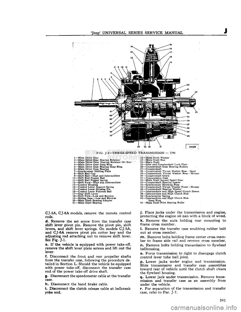
FIG.
J-2—THREE-SPEED
TRANSMISSION
— T90 1—
Main
Drive
Gear
2—
Main
Drive
Gear
Bearing
Retainer
3—
Main
Drive
Gear
Bearing
Retainer Oil
Seal
4—
Main
Drive
Gear
Snap
Ring
5—
Main
Drive
Gear
Bearing
Snap
Ring
6—
Main
Drive
Gear
Bearing
7—
Synchronizer
Shifting Plate
8—
Shift
Rail
Cap
9—
Shift
Rail—High
and Intermediate
10—
Shift
Rail
Poppet
Ball
11—
Shift
Rail
Poppet
Spring
12—
Shift
Fork—High
and Intermediate
13—
Control
Housing
14—
Control
Lever
Support
Spring
15—
Control
Lever
Housing Pin
16—
Control
Lever
Fulcrum
Ball
17—
Gear
Shift
Lever
18—
Shift
Fork—Low
and Reverse
19—
Sliding
Gear—Low
and Reverse
20—
Main
Shaft
Bearing
Adapter
21—
Main
Shaft
Bearing
22—
Main
Shaft
Washer
23—
Main
Shaft Nut
24—
Main
Shaft
25—
Idler
and Countershaft
Lock
Plate
26—
^Countershaft
Gear
Bearing
Rollers
2
7—Countershaft
28—
Countershaft
Thrust
Washer
Rear—Steel
29—
Countershaft
Thrust
Washer
Rear—Bronze
30—
Countershaft
Gears
31—
Transmission
Case
32—
Main
Shaft Second Speed
Gear
33—
Countershaft
Bearing
Spacer
34—
Synchronizer
Blocking
Ring
35—
Countershaft
Thrust
Washer
Front—Bronze
36—
Countershaft
Bearing
Washer
37—
Intermediate
and High Speed
Clutch
Sleeve
38—
Intermediate
and High
Clutch
Hub
39—
Synchronizer
Spring
40—
Intermediate
and High
Clutch
Hub
Snap
Ring
41—
Main
Shaft Pilot
Bearing
Roller
CJ-5A,
CJ-6A
models, remove the remote control
rods.
d.
Remove the set screw from the transfer case
shift lever pivot pin. Remove the pivot pin, shift
levers,
and shift lever springs. On models
CJ-5A,
and
CJ-6A
remove pivot pin cotter key and the
adjusting
rod attaching nut to remove shift lever.
See
Fig.
J-l.
e. If the vehicle is equipped with power take-off,
remove the shift lever plate screws and lift out the
lever.
f. Disconnect the front and
rear
propeller shafts
from
the transfer case, following the procedure de
tailed
in Section
L.
Should the vehicle be equipped
with
power take-off, disconnect the transfer case end of the power take-off drive shaft.
g. Disconnect the
speedometer
cable at the transfer case.
h.
Disconnect the hand brake cable.
i.
Disconnect the clutch release cable at beilcrank
yoke end.
j.
Place
jacks
under the transmission and engine,
protecting the
engine
oil pan with a block of wood,
k.
Remove the nuts holding
rear
mounting to
frame
cross member.
I.
Remove the transfer case snubbing rubber bolt
nut at cross member.
m.
Remove
bolts
holding frame center cross mem
ber
to frame side
rail
and remove cross member,
n.
Remove
bolts
holding transmission to flywheel
bellhousing.
o.
Force
transmission to right to
disengage
clutch
control
lever tube
ball
joint.
p.
Lower
jacks
under
engine
and transmission.
Slide
transmission and transfer case assemblies
toward
rear
of vehicle until the clutch shaft clears the flywheel housing.
q.
Lower
jack
under transmission. Remove trans mission and transfer case as an assembly from
under
the vehicle.
r.
For separation of the transmission and transfer
case, refer to Par. J-7. 241
Page 257 of 376
'Jeep*
UNIVERSAL
SERIES
SERVICE
MANUAL
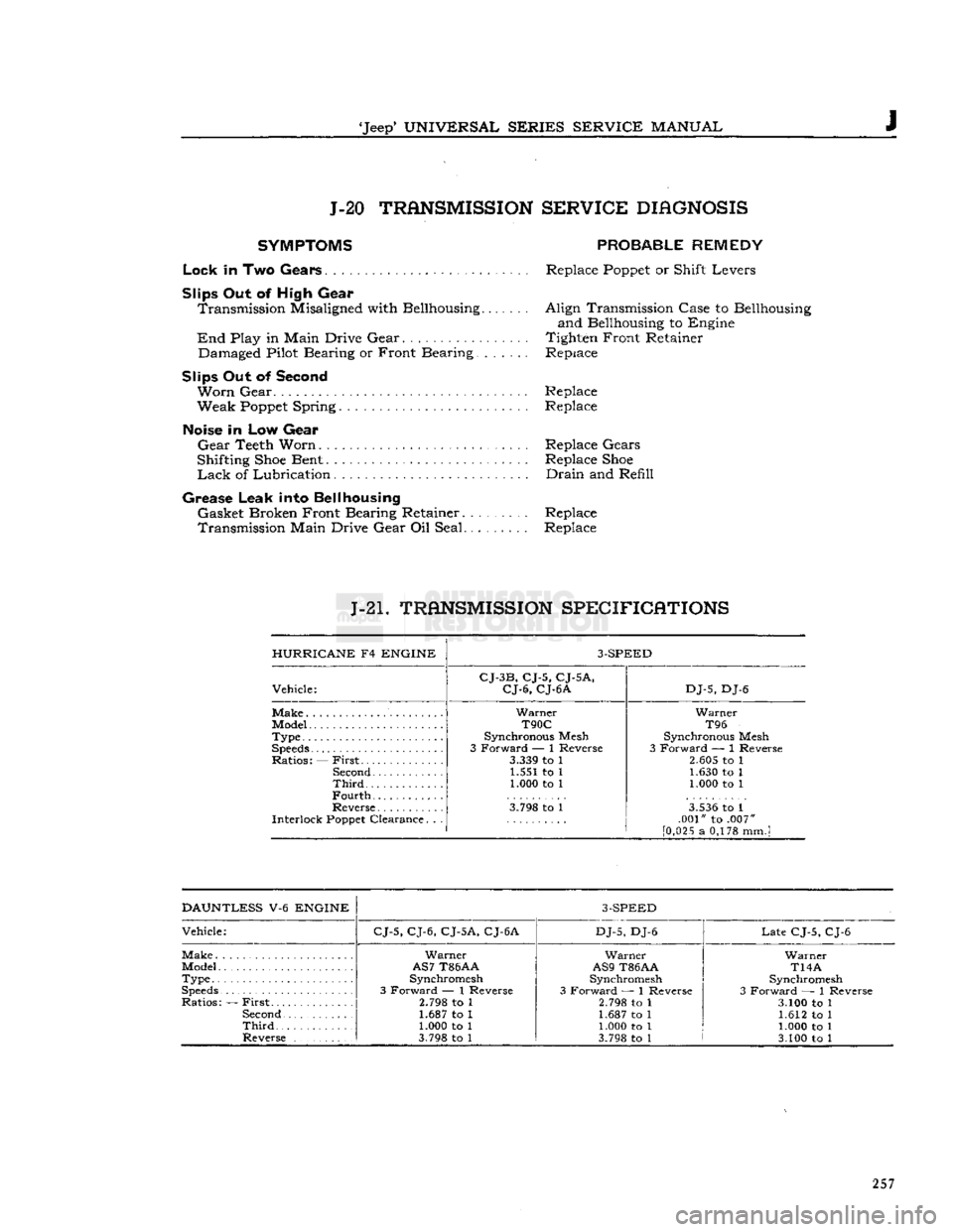
J J-20
TRANSMISSION
SERVICE
DIAGNOSIS
SYMPTOMS
PROBABLE
REMEDY
Lock
in Two
Gears
Replace
Poppet
or Shift Levers
Slips
Out of High Gear Transmission Misaligned with Bellhousing
End
Play in Main Drive Gear Damaged Pilot Bearing or Front Bearing.
Slips
Out of Second
Worn
Gear Replace
Weak
Poppet
Spring Replace
Noise
in Low Gear
Gear
Teeth Worn Replace Gears
Shifting
Shoe
Bent Replace
Shoe
Lack
of Lubrication Drain and Refill
Grease
Leak into Bellhousing Gasket Broken Front Bearing Retainer Replace
Transmission Main Drive Gear Oil Seal Replace Align Transmission Case to Bellhousing
and Bellhousing to Engine
Tighten Front Retainer
Replace
J-21.
TRANSMISSION
SPECIFICATIONS
HURRICANE
F4
ENGINE
3-SPEED
Vehicle:
CJ-3B,
CJ-5,
CJ-5A,
CJ-6,
CJ-6A
DJ-5,
DJ-6
Make
Type
Speeds
Ratios: —
First
Second
Third
Fourth
Warner
T90C
Synchronous Mesh
3 Forward — 1 Reverse
3.339
to 1 1.551 to 1 1.000 to 1
Warner
T96
Synchronous Mesh
3 Forward — 1 Reverse
2.605
to 1 1.630 to 1
1.000 to 1
Reverse
Interlock
Poppet
Clearance. . .
3.798
to 1
3.536
to 1
.001" to .007"
[0,025
a 0,178 mmJ
DAUNTLESS
V-6
ENGINE
3-SPEED
Vehicle:
CJ-5,
CJ-6,
CJ-5A,
CJ-6A
DJ-5,
DJ-6
Late
CJ-5, CJ-6
Make
Warner
Warner Warner
Model
AS7
T86AA
AS9
T86AA
T14A
Type..
Synchromesh
Synchromesh Synchromesh
Speeds
3 Forward — 1 Reverse 3 Forward — 1 Reverse 3 Forward — 1 Reverse
Ratios: —
First
2.798
to 1
2.798
to 1
3.100 to 1
Second
1.687 to 1 1.687 to 1 1.612 to 1
Third
1.000 to 1
1.000 to 1 1.000 to 1
Reverse
3.798
to 1
3.798
to 1 3.100 to 1 257
Page 260 of 376
Jl
FOUR-SPEED
TRANSMISSION
J1-1.
GENERAL
A
model T-98 four-speed transmission with a cane- type shift is optional on 'Jeep* Models CJ-5 and
CJ-6
equipped with the Hurricane F4
engine.
A model T-18 four-speed transmission is optional on
the 'Jeep* Model
CJ-5
equipped with the Dauntless
V6
engine.
These transmissions provide four
speeds
forward
and one reverse with synchromesh
engage
ment in second,
third,
and fourth speed.
For
quick identification, the optional
4-speed
transmission is 11%"
[30,16
cm.] long whereas the
standard
3-speed
transmission is 8"
[20,32
cm.] long. However the instructions for removal and
installation of the two transmissions are the same.
J1-2.
Four-Speed
Transmission Removal Use the procedure outlined under the heading,
"TRANSMISSION
REMOVAL"
Section J Par.
J-6.
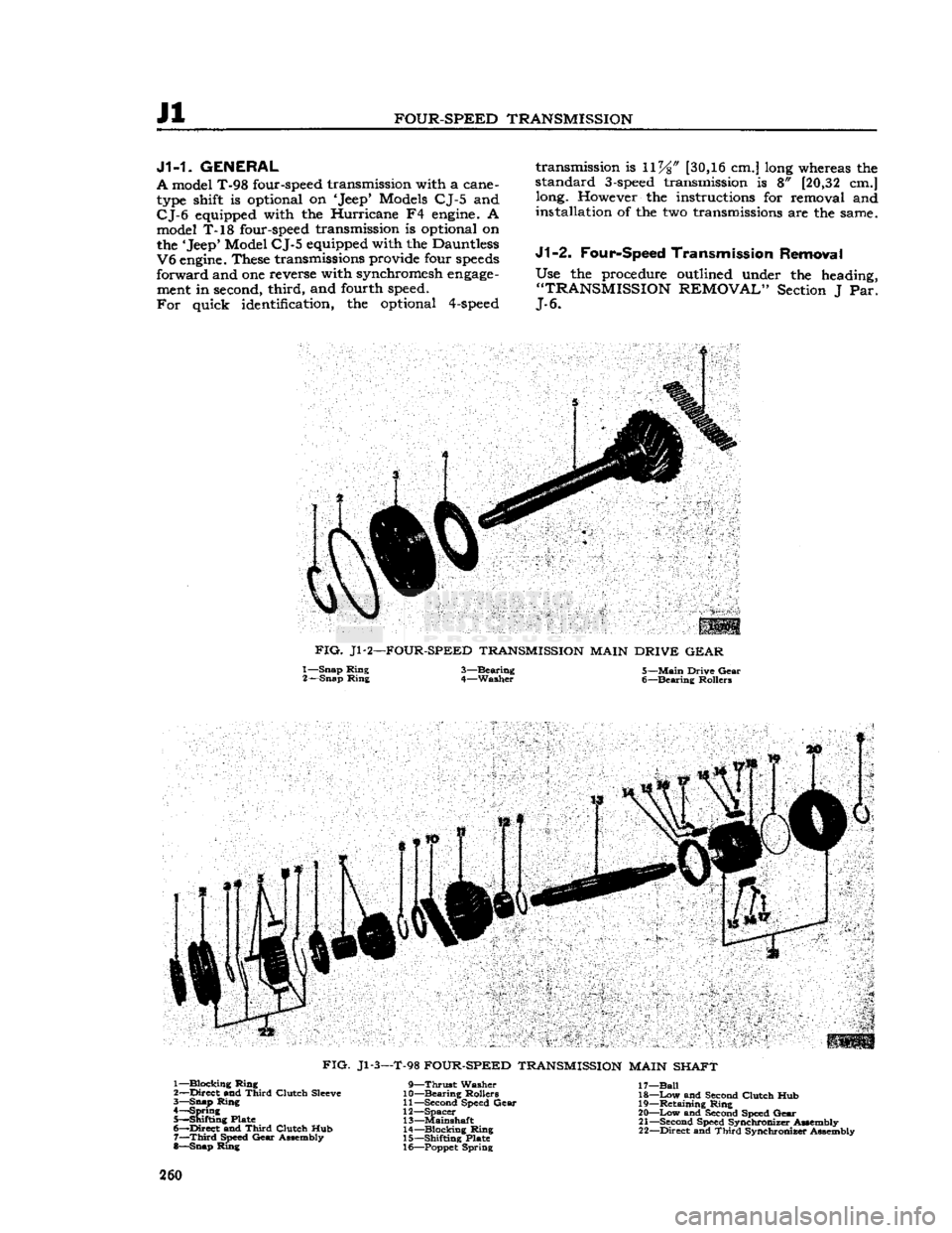
FIG.
Jl-2—FOUR-SPEED TRANSMISSION MAIN DRIVE
GEAR
1—
Snap
Ring
3—Bearing 5—Main
Drive
Gear
2—
Snap
Ring
4—Washer 6—Bearing Rollers
FIG.
Jl-3—T-98
FOUR-SPEED TRANSMISSION MAIN SHAFT 1—
Blocking
Ring
2—
Direct
and
Third
Clutch
Sleeve
3—
Snap
Ring
4—
Spring
5—
Shifting
Plate
6—
Direct
and
Third
Clutch
Hub 7—
Third
Speed
Gear
Assembly
8—
Snap
Ring
9—Thrust
Washer
10—
Bearing
Rollers
11—
Second Speed
Gear
12—
Spacer
13—
Mainshaft
14—
Blocking
Ring
15—
Shifting
Plate
16— Poppet
Spring
17—
Ball
18—
Low
and Second
Clutch
Hub 19—
Retaining
Ring
20—
Low
and Second Speed
Gear
21—
Second Speed
Synchronizer
Assembly
22—
Direct
and
Third
Synchroniser Assembly 260
Page 266 of 376
Jl
FOUR-SPEED
TRANSMISSION
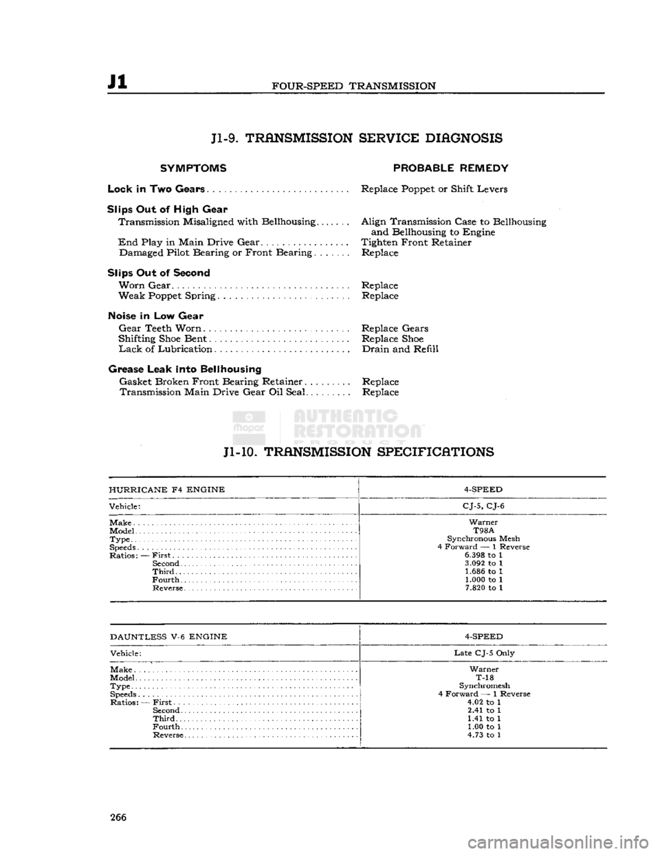
Jl-9.
TRANSMISSION
SER¥ICE
DIAGNOSIS
SYMPTOMS
Lock
In Two Gears
Slips
Out of High Gear Transmission Misaligned with Bellhousing
End
Play in Main Drive Gear Damaged Pilot Bearing or Front Bearing.
Slips Out of
Second
Worn
Gear
Weak
Poppet
Spring
PROBABLE
REMEDY
Replace
Poppet
or Shift Levers
Align Transmission Case to Bellhousing and Bellhousing to Engine
Tighten Front Retainer Replace
Replace Replace
Noise
in Low Gear
Gear
Teeth Worn. Replace Gears
Shifting
Shoe
Bent Replace
Shoe
Lack
of Lubrication Drain and Refill
Grease
Leak into Bellhousing Gasket Broken Front Bearing Retainer......... Replace Transmission Main Drive Gear Oil Seal Replace
Jl-10.
TRANSMISSION
SPECIFICATIONS
HURRICANE
F4
ENGINE
4-SPEED
Vehicle:
CJ-5,
CJ-6
Warner
T98A
Type..
• Synchronous Mesh
4 Forward — 1 Reverse
Ratios: —
First
. .
6.398
to 1
Second
3.092
to 1
Third
1.686 to 1
Fourth
1.000 to 1
7.820
to 1
DAUNTLESS
V-6
ENGINE
4-SPEED
Vehicle:
Late
CJ-5 Only
Warner
Model T-18
Type Synchromesh
4 Forward — 1 Reverse
Ratios: —
First
4.02 to 1
Second
2.41 to 1
Third
1.41 to 1
Fourth
1.00 to 1
Reverse 4.73 to 1 266
Page 267 of 376
'Jeep'
UNIVERSAL SERIES SERVICE
MANUAL
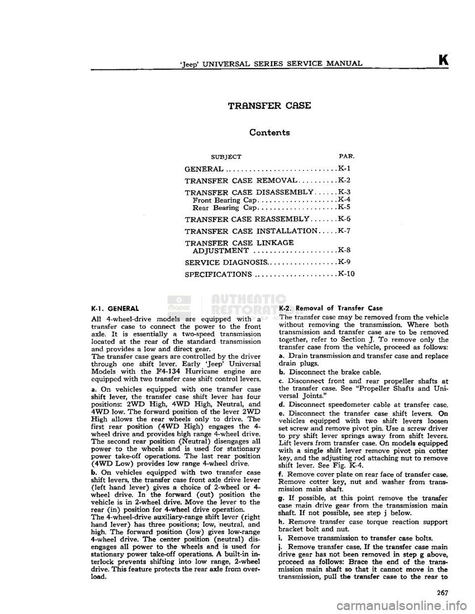
ft
TRANSFER CASE
Contents
SUBJECT
PAR.
GENERAL
. . .K-1
TRANSFER CASE REMOVAL
K-2
TRANSFER CASE DISASSEMBLY
K-3
Front
Bearing Cap K-4
Rear
Bearing Cap K-5
TRANSFER CASE REASSEMBLY.
. .K-6
TRANSFER CASE INSTALLATION
K-7
TRANSFER CASE LINKAGE
ADJUSTMENT
K-8
SERVICE
DIAGNOSIS
K-9
SPECIFICATIONS
.K-10
K-1. GENERAL
All
4-wheel-drive models are equipped with a
transfer
case to connect the power to the front
axle.
It is essentially a
two-speed
transmission
located at the
rear
of the standard transmission
and
provides a low and direct gear.
The
transfer case gears are controlled by the
driver
through
one shift lever.
Early
'Jeep'
Universal
Models with the F4-134
Hurricane
engine
are equipped with two transfer case shift control levers.
a.
On vehicles equipped with one transfer case
shift
lever, the transfer case shift lever has four
positions: 2WD
High,
4WD
High,
Neutral, and
4WD
low. The forward position of the lever 2WD
High
allows the
rear
wheels only to drive. The
first
rear
position (4WD High)
engages
the 4- wheel drive and provides high range 4-wheel drive.
The
second
rear
position (Neutral)
disengages
all power to the wheels and is used for stationary
power take-off operations. The last
rear
position
(4WD
Low) provides low range 4-wheel drive.
b.
On vehicles equipped with two transfer case
shift
levers, the transfer case front axle drive lever (left hand lever)
gives
a choice of 2-wheel or 4-
wheel drive. In the forward (out) position the
vehicle is in 2-wheel drive. Move the lever to the
rear
(in) position for 4-wheel drive operation.
The
4-wheel-drive
auxiliary-range
shift lever (right
hand
lever) has three positions; low, neutral, and
high.
The forward position (low)
gives
low-range
4-wheel drive. The center position (neutral) dis
engages
all power to the wheels and is used for
stationary
power take-off operations. A built-in in
terlock
prevents shifting into low range, 2-wheel
drive.
This
feature protects the
rear
axle from over
load.
K-2.
Removal of
Transfer
Case
The
transfer case may be removed from the vehicle
without removing the transmission. Where both
transmission
and transfer case are to be removed
together,
refer to Section J. To remove only the
transfer
case from the vehicle, proceed as follows:
a.
Drain
transmission
and transfer case and replace
drain
plugs.
b.
Disconnect the brake cable.
c.
Disconnect front and
rear
propeller shafts at
the transfer case. See "Propeller Shafts and
Uni
versal
Joints."
d.
Disconnect
speedometer
cable at transfer case. e. Disconnect the transfer case shift levers. On
vehicles equipped with two shift levers
loosen
set screw and remove pivot pin. Use a screw
driver
to pry shift lever springs away from shift levers.
Lift
levers from transfer case. On models equipped
with
a single shift lever remove pivot pin cotter
key,
and the adjusting rod attaching nut to remove
shift
lever. See Fig. K-4.
f. Remove cover plate on
rear
face of transfer case.
Remove
cotter key, nut and washer from trans
mission
main shaft.
g. If possible, at this point remove the transfer case main drive gear from the transmission main
shaft.
If not possible, see
step
j below.
h.
Remove transfer case torque reaction support
bracket
bolt and nut.
i.
Remove transmission to transfer case bolts.
j.
Remove transfer case. If the transfer case main
drive
gear has not been removed in
step
g above,
proceed as follows:
Brace
the end of the trans
mission
main shaft so that it cannot
move
in the
transmission,
pull
the transfer case to the
rear
to 267
Page 276 of 376
L
PROPELLER
SHAFTS
AND
UNIVERSAL JOINTS
move
the snap rings, pinch the ends
together
with
a
pair
of pliers. If the rings do not readily snap
out of the groove, tap the end of the bearing lightly
which
will
relieve pressure against the rings.
After
removing the snap rings, press on the end of
one bearing until the
opposite
bearing is pushed
from
the yoke arm.
Turn
the joint over and press
the first bearing back out of that arm by pressing
on the
exposed
end of the
journal
shaft. Use a
soft
ground drift with a flat face about [0,8 mm.]
smaller
in diameter than the
hole
in the yoke arm
and
drive it out, otherwise there is danger of damaging the bearing.
Repeat
this operation for the other two bearings,
then lift out
journal
assembly by sliding it to one
side.
L-4.
Snap
Ring
Type Assembly
Wash
all parts in cleaning solvent and inspect the
parte
after cleaning. Replace any parts that indicate
extensive
wear.
It is advisable to install new gaskets
on the
journal
assembly regardless of the condition of the old gaskets. Make certain that the grease
channel
in each
journal
trunnion is open.
Pack
the bearing
cones
one-third
full
of lubricant
and
install the rollers.
Draw
the bearings into the end yoke arm and seat
them firmly against the bearing shoulders. Hold
the bearings in a vertical position to prevent the
needles
from dropping out until the joint is as sembled. If the joint binds when assembled, tap
the arms lightly to relieve any pressure on the bear
ings at the end of the
journal.
L-5.
U-Bolt
Type Disassembly
Removal
of the attaching "U"-bolt releases one set
of bearing races. Slide the propeller shaft into the
yoke flange to remove them using care not to
lose
the rollers.
After
the removal of the one set of bearing races,
release the other set by removing the snap rings
in
the
sleeve
yoke by pinching the ends
together
with
a
pair
of pliers. Should the rings
fail
to snap
readily
from the groove, tap the end of the bearing
lightly,
which
will
relieve the pressure against them.
Press
on the end of one bearing, until the
opposite
bearing
is pushed out of the yoke arm.
Turn
the
universal
joint over and press the first bearing out
by pressing on the
exposed
end of the
journal
as
sembly. Use a
soft
ground drift with a flat face about
\{i
[0,8 mm.] smaller in diameter than the
hole
in the yoke
arm
and drive out the bearing.
Lift
the
journal
out by sliding to one side.
Clean
all
parts
and check for wear.
L-6.
U-Bolt Type Assembly
Wash
all parts in cleaning solvent and inspect the
parts
after cleaning. Replace any parts that indicate
extensive
wear.
It is advisable to install new gaskets
on the
journal
assembly regardless of the condition
of the old gaskets. Make certain that the grease
channel
in each
journal
trunnion is open.
Pack
the bearing
cones
one-third
full
of lubricant
and
install the rollers.
Draw
the bearings into the end yoke arm and seat
them firmly against the bearing shoulders. Hold the
bearings in a vertical position to prevent the
needles
from dropping out until the joint is as
sembled. If the joint binds when assembled, tap the arms lightly to relieve any pressure on the
bearings at the end of the
journal.
Tighten the
U-bolts equally. U-bolt torque wrench reading is 15 to 20 lb-ft. [2,07 a 2,76 kg-m.].
When
installing the assembly in the vehicle be sure
that the arrows on the propeller shaft and yoke
sleeve
are in alignment as shown in Fig. L-2, or
that the unmarked joints are aligned with the yokes in the same parallel plane.
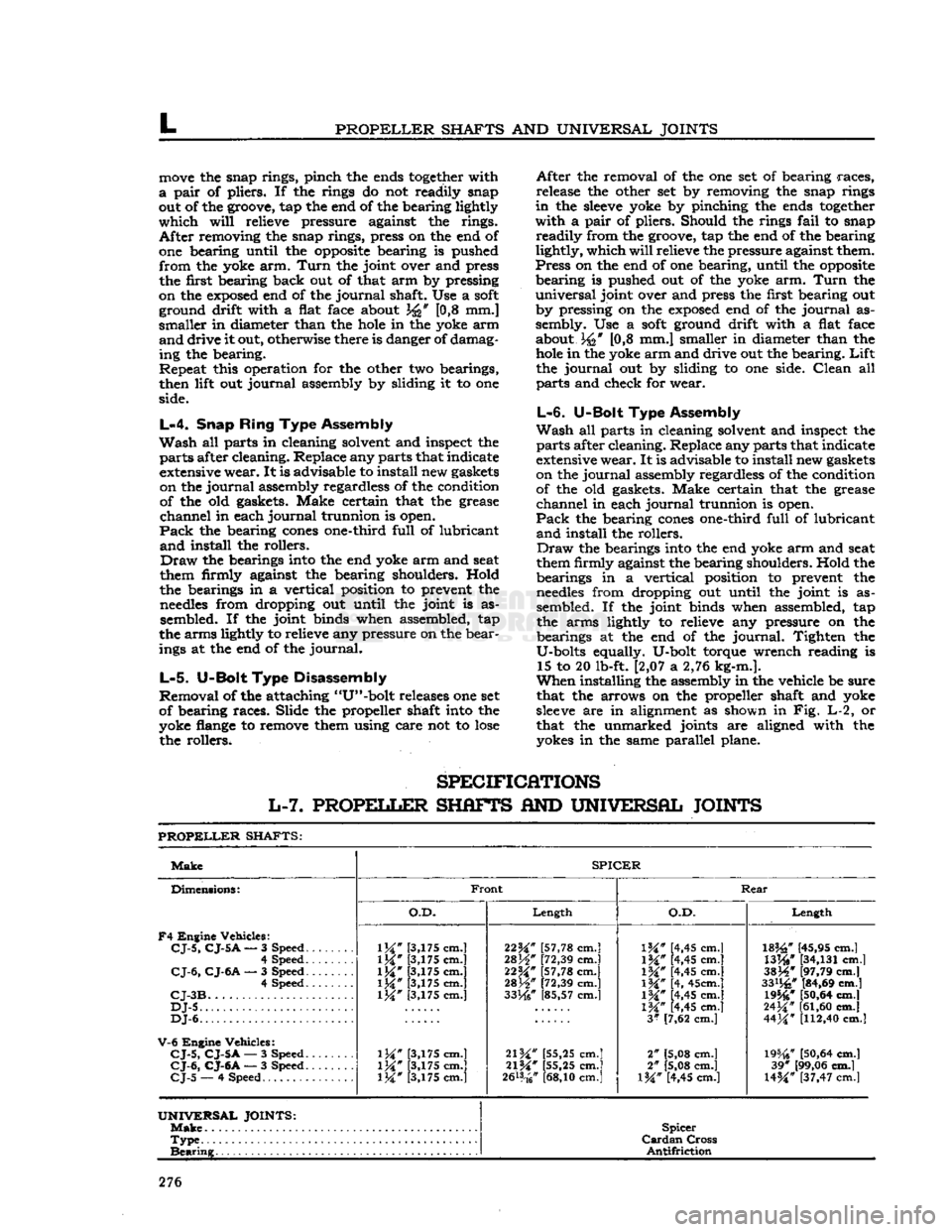
SPECIFICATIONS
L-7.
PROPELLER
SHAFTS
AND
UNIVERSAL JOINTS
PROPELLER
SHAFTS:
Make
SPICER
Dimensions:
F4
Engine Vehicles:
CJ-5,
CJ-5
A
— 3 Speed.
......
4 Speed
CJ-6,
CJ-6A
— 3 Speed 4 Speed
CJ-3B
DJ-5
DJ-6.
V-6
Engine Vehicles:
CJ-5,
CJ-5A
— 3 Speed.
CJ-6,
CJ-6A
— 3 Speed.
CJ-5
— 4 Speed
Front
Rear
Dimensions:
F4
Engine Vehicles:
CJ-5,
CJ-5
A
— 3 Speed.
......
4 Speed
CJ-6,
CJ-6A
— 3 Speed 4 Speed
CJ-3B
DJ-5
DJ-6.
V-6
Engine Vehicles:
CJ-5,
CJ-5A
— 3 Speed.
CJ-6,
CJ-6A
— 3 Speed.
CJ-5
— 4 Speed
O.D.
Length
O.D.
Length
Dimensions:
F4
Engine Vehicles:
CJ-5,
CJ-5
A
— 3 Speed.
......
4 Speed
CJ-6,
CJ-6A
— 3 Speed 4 Speed
CJ-3B
DJ-5
DJ-6.
V-6
Engine Vehicles:
CJ-5,
CJ-5A
— 3 Speed.
CJ-6,
CJ-6A
— 3 Speed.
CJ-5
— 4 Speed
1M"
[3,175 cm.]
1M*
[3,175 cm.]
\W
[3,175 cm.]
1M*
[3,175 cm.] [3,175 cm.]
\W
[3,175 cm.]
\W
[3,175 cm.] [3,175 cm.] 22^" [57,78 cm.]
28H"
[72,39 cm.]
22M*
[57,78 cm.]
mW
[72,39 cm.]
33He"
[85,57 cm.]
21W
[55,25 cm.]
21%"
[55,25 cm.]
2&*
cm.]
IK"
[4,45 cm.]
1M#
[4,45 cm.]
\%"
[4,45 cm.]
\%"
[4, 45cm.]
IW
[4,45 cm.]
1M*
[4,45 cm.]
3*
[7,62 cm.]
2" [5,08 cm.]
2" [5,08 cm.]
l%" [4,45 cm.]
182£"
[45,95 cm.]
WW
[34,131
cm.]
3SJ4*
[97,79 cm.]
33%"
[84,69 cm.] 19546*
[50,64
cm.]
24^"
[61,60
cm.]
44M*
[112,40
cm.]
19%?
[50,64
cm.] 39* [99,06 cm.]
U%"
[37,47 cm.l
UNIVERSAL
JOINTS:
Make
Spicer
Cardan
Cross
Antifriction
Type
Spicer
Cardan
Cross
Antifriction
Bearing
Spicer
Cardan
Cross
Antifriction
276
Page 286 of 376
FRONT
AXLE
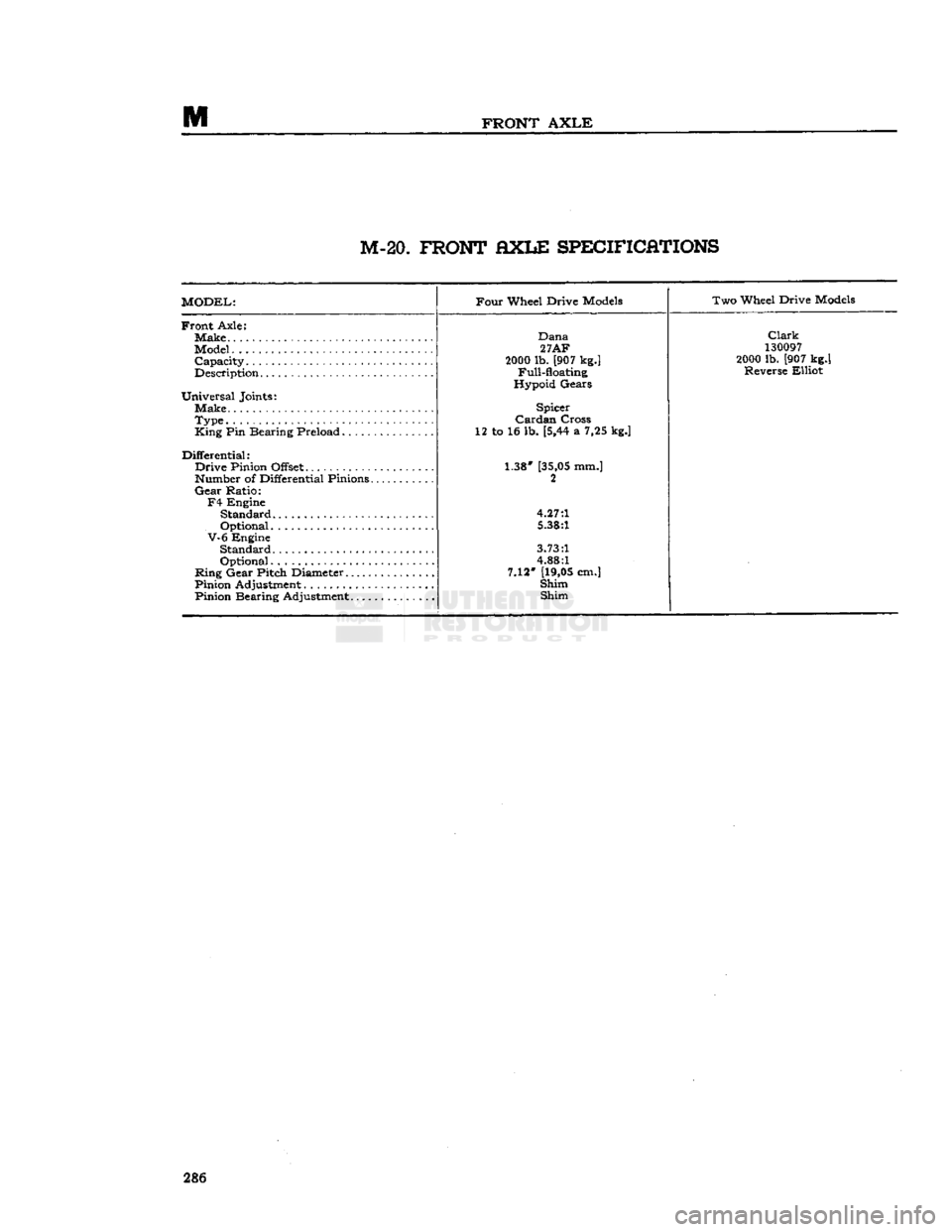
M-20.
FRONT
AXLE
SPECIFICATIONS
MODEL:
Four
Wheel Drive
Models
Two Wheel Drive
Models
Front
Axle:
Make.
Model
Capacity
Description
Universal
Joints: Make
Type.
King
Pin Bearing Preload
Differential:
Drive
Pinion Offset:
Number of Differential Pinions
Gear
Ratio:
F4
Engine
Standard
Optional
V-6
Engine
Standard
Optional
Ring
Gear Pitch Diameter
Pinion Adjustment
Pinion Bearing Adjustment
Dana
27AF
2000
lb. [907 kg.] Full-floating
Hypoid Gears
Spicer
Cardan
Cross
12 to 16 lb. [5,44 a 7,25 kg.]
1.38*
[35,05
mm.] 2
4.27:1
5.38:1
3.73:1
4.88:1
7.12'
[19,05
cm.]
Shim Shim
Clark
130097
2000
lb. [907 kg.] Reverse Elliot 286
Page 301 of 376
'Jeep'
UNIVERSAL
SERIES SERVICE
MANUAL
N
13189
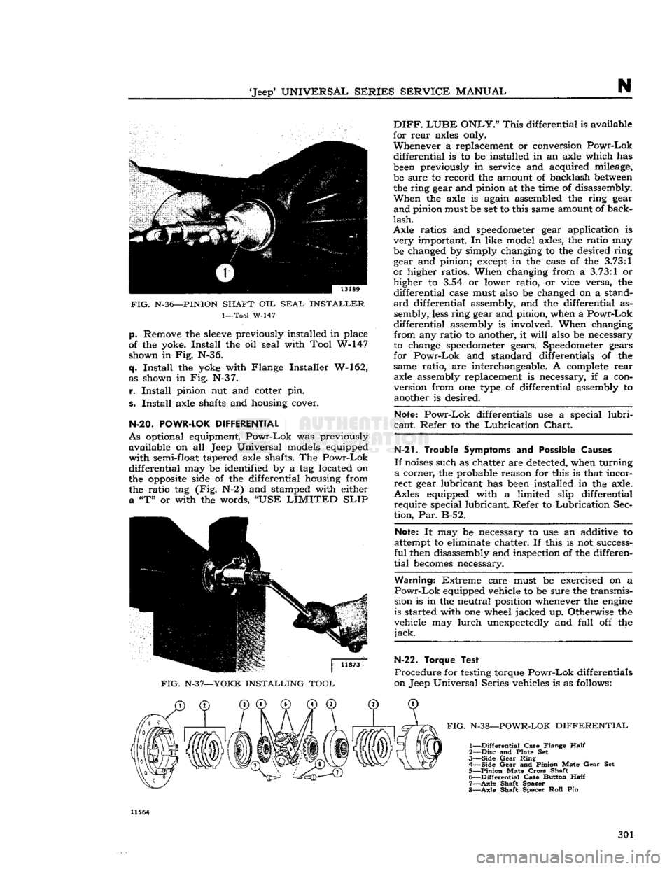
FIG.
N-36—PINION
SHAFT OIL
SEAL
INSTALLER
1—Tool
W-147
p.
Remove
the
sleeve
previously installed in
place
of
the yoke. Install the oil
seal
with
Tool
W-147 shown in Fig. N-36.
q. Install the yoke
with
Flange
Installer W-162,
as shown in Fig. N-3 7.
r.
Install pinion nut and cotter pin.
s. Install axle
shafts
and housing cover.
N-20.
POWR-LOK
DIFFERENTIAL
As
optional equipment, Powr-Lok was previously available on all
Jeep
Universal
models
equipped
with
semi-float
tapered
axle
shafts.
The Powr-Lok
differential
may be identified by a tag located on
the opposite
side
of the differential housing
from
the ratio tag (Fig. N-2) and
stamped
with
either a "T" or
with
the words, "USE
LIMITED
SLIP
FIG.
N-37—YOKE INSTALLING TOOL
DIFF.
LUBE
ONLY."
This differential is available
for
rear
axles
only.
Whenever a
replacement
or conversion Powr-Lok
differential
is to be installed in an axle which has
been
previously in
service
and acquired mileage, be
sure
to record the amount of backlash
between
the ring
gear
and pinion at the time of
disassembly.
When the axle is again
assembled
the ring
gear
and pinion must be set to this
same
amount of
back
lash.
Axle
ratios and
speedometer
gear
application is very important. In
like
model
axles,
the ratio may
be
changed
by simply changing to the desired ring
gear
and pinion;
except
in the
case
of the
3.73:1
or higher ratios. When changing
from
a
3.73:1
or higher to 3.54 or lower ratio, or vice
versa,
the
differential
case
must
also
be
changed
on a
stand
ard differential
assembly,
and the differential as sembly,
less
ring
gear
and pinion, when a Powr-Lok
differential
assembly
is involved. When changing
from
any ratio to
another,
it
will
also
be
necessary
to
change
speedometer
gears.
Speedometer
gears
for
Powr-Lok and
standard
differentials of the
same
ratio, are
interchangeable.
A complete
rear
axle
assembly
replacement
is
necessary,
if a con
version
from
one type of differential
assembly
to
another
is desired.
Note: Powr-Lok differentials use a special
lubri
cant.
Refer to the Lubrication Chart.
N-21.
Trouble Symptoms and
Possible
Causes
If
noises
such
as
chatter
are
detected,
when turning
a corner, the probable
reason
for this is that incor
rect
gear
lubricant has
been
installed in the axle.
Axles
equipped
with
a
limited
slip differential require special lubricant. Refer to Lubrication
Sec
tion,
Par. B-52.
Note: It may be
necessary
to use an additive to
attempt to eliminate
chatter.
If this is not
success
ful
then
disassembly
and inspection of the differen
tial
becomes
necessary.
Warning:
Extreme
care
must be exercised on a
Powr-Lok
equipped vehicle to be
sure
the transmis
sion is in the neutral position
whenever
the
engine
is
started
with
one wheel jacked up. Otherwise the
vehicle may lurch unexpectedly and
fall
off the
jack.
N-22. Torque Test
Procedure
for testing torque Powr-Lok differentials
on
Jeep
Universal
Series
vehicles is as follows:
FIG.
N-38—POWR-LOK DIFFERENTIAL
1—
Differential
Case Flange
Half
2—
Disc
and Plate Set
3—
Side
Gear
Ring
4— Side
Gear
and Pinion Mate
Gear
Set
5—
Pinion
Mate
Cross
Shaft 6—
Differential
Case Button
Half
7—
Axle
Shaft Spacer
8—
Axle
Shaft Spacer
Roll
Pin 11564
301
Page 303 of 376
'Jeep*
UNIVERSAL
SERIES SERVICE
MANUAL
N
scribed
in
Pars.
N-ll through N-l9 for standard
axles, with the exception of the following torque
recommendations. Torque the differential case
bearing
cap screws 70 to 90 lb-ft. [9,7 a 12,4 kg-m.]
and
the cover screws 15 to 25 lb-ft. [2,1 a 3,4
kg-m.].
The ring gear screws on axles with Powr-
Lok
differentials should be torqued as follows:
Model
30 and 44 axles 35 to 55 lb-ft. [4,84 a 7,60 kg-m.].
N-24. TRAC-LOK DIFFERENTIAL
As
optional equipment
Trac-Lok
Model 44 differen
tial
is available on all Jeep Universal vehicles equipped with semi-float flanged axle shafts.
A
conventional differential transmits all of the
ring
gear torque through the differential gears to the axle shafts. Torque is at all
times
equal on the axle shafts, and if one wheel slips, the other wheel
can
only put out as much torque as the slipping
wheel.
The
Trac-Lok
differential is similar,
except
that
part
of the torque from the ring gear is trans mitted through clutch packs
between
the side gears
and
differential case. The multiple disc clutches
with
radial
grooves
on the plates and concentric
grooves
on the discs are
engaged
by a preload
from
Belleville springs, plus separating forces from
the side gears as torque is applied through the
ring
gear.
The
Trac-Lok
construction permits differential action when required for turning corners and transmits equal torque to both
wheels
when driving
straight
ahead. However, when one wheel tries to spin due to leaving the ground, a patch of ice,
etc., the clutch packs automatically provide more
torque to the wheel which is not trying to spin.
It
can be
seen
then that the
Trac-Lok
differential
resists wheel spin on bumpy roads and provides
more pulling power when one wheel tries to slip.
In
many cases of differences in traction, pulling
power
will
be automatically provided until both
wheels
start to slip.
In
diagnosis of vehicle operators' complaints, it
is important to recognize two things:
a.
If, with unequal traction, both
wheels
slip, the
Trac-Lok
has
done
all it can possibly do.
b.
In extreme cases of differences in traction, the
wheel with least traction may spin after the
Trac-
Lok
has transferred as much torque as possible
to the non-slipping wheel.
N-25.
Lubrication
The
Trac-Lok
differential requires a special
lubri
cant
and ordinary multipurpose gear lubricants
MUST
NOT be used. Use only 'Jeep* Differential
Oil,
Part
No. 94557.
Trac-Lok
differential may be cleaned only by disassembling the unit and wiping with clean rags. Do not flush the
Trac-Lok
unit.
Note:
The
Trac-Lok
differential is serviced at the
same time intervals as the standard differential.
N-26.
Trouble
Symptoms
If
noises
or roughness, such as chatter, are present
in
turning corners, the probable cause is incorrect
or
contaminated lubricant.
Before any differential is removed and disassem
bled for chatter complaints, the correctness of
lubri
cant
can and should be determined.
A
complete
lubricant
drain,
and
refill
with specified
Limited
Slip Differential lubricant
will
usually
correct
chatter.
The
following procedure is recommended to ensure
complete
removal of old lubricant.
a.
Warm
the lubricant by vehicle road operation,
or
5 minutes of operation in gear at 30 mph with
both
wheels
off the ground on a hoist.
Caution:
Never place the transmission in gear with
the
engine
running when only one wheel of a
Limited
Slip Differential equipped vehicle is raised.
The
vehicle might drive itself off the
jack
and produce damage or
injury.
b.
Drain
lubricant while
warm.
Remove
drain
plug
or
cover to
drain
completely. If cover is removed,
it
may be necessary to replace gasket at this time.
c.
Refill
axle with specified
Limited
Slip Differen
tial
lubricant.
d.
Operate the vehicle for approximately ten miles
[16,09
km.], making at least ten figure 8 turns
to flush the old lubricant out of the clutch packs.
e.
Repeat
steps
b, c, and d, making sure to replace
the cover gasket if required in
step
c.
f. It is possible that slight chatter, requiring ad
ditional
vehicle operation, may remain after
step
e. If chatter persists after 100 miles
[160,9
km.]
of vehicle operation, or remains severe after
step
e above, disassembly and repair
will
be necessary.
N-27.
Unit
Inoperative
Proper
performance and capabilities of
Limited
Slip
Differentials are
often
misunderstood. No
precise
methods
of measuring
Limited
Slip Dif
ferential
performance are generally available in the field. A functioning unit can be determined by
relatively
simple vehicle operational
tests,
as
follows:
a.
Place one wheel on
good
dry pavement, and the
other on ice, mud, grease, etc.
b.
Gradually
increase
engine
rpm to obtain maxi
mum
traction
prior
to "break-a-way." The ability
to
move
the vehicle
effectively
will
demonstrate
proper
performance.
c.
If extremely slick surfaces, such as ice or grease,
are
used
some
question may exist as to proper per
formance at
step
b. In
these
extreme cases a prop
erly
performing
Limited
Slip Differential
will
pro
vide greater "pulling" power by lightly applying
the parking brake.
N-23.
Trac-Lok
Differential Disassembly
and
Reassembly
It
is recommended that the
complete
axle assembly
be removed from the vehicle, when it
becomes
necessary to remove the
Trac-Lok
from the hous
ing.
Refer to Par. N-3 and N-12 for removal of axle shafts and differential case from axle housing. 303
Page 311 of 376
Jeep'
UNIVERSAL SERIES SERVICE
MANUAL
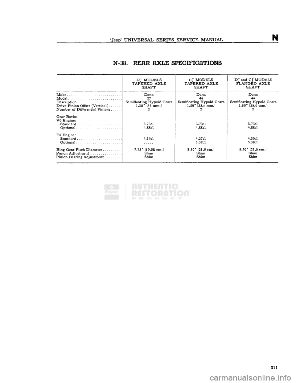
N N-38.
REfiR flXLE SPECIFICATIONS
DJ MODELS
TAPERED AXLE SHAFT CJ MODELS
TAPERED AXLE SHAFT DJ and CJ MODELS
FLANGED AXLE SHAFT
Make
Model
Description Drive Pinion Offset (Vertical)
Number of Differential Pinions.......
Gear Ratio:
V6 Engine:
Standard
Optional
F4 Engine: Standard
Optional
Ring Gear Pitch Diameter
Pinion Adjustment
Pinion Bearing Adjustment Dana
27
Semifloating Hypoid Gears 1.38" [35 mm.] 2
3.73:1
4.88:1
4.56:1
7.75" [19,68 cm.] Shim
Shim Dana
44
Semifloating Hypoid Gears 1.50" [38,0 mm.] 2
3.73:1
4.88:1
4.27:1
5.38:1
8.50" [21,6 cm.] Shim Shim Dana
44
Semifloating Hypoid Gears 1.50" [38,0 mm.] 2
3.73:1
4.88:1
4.56:1
5.38:1
8.50" [21,6 cm.] Shim Shim 311