ECU JEEP CJ 1953 Owner's Manual
[x] Cancel search | Manufacturer: JEEP, Model Year: 1953, Model line: CJ, Model: JEEP CJ 1953Pages: 376, PDF Size: 19.96 MB
Page 93 of 376
'Jeep'
UNIVERSAL
SERIES SERVICE
MANUAL
Dl Caution:
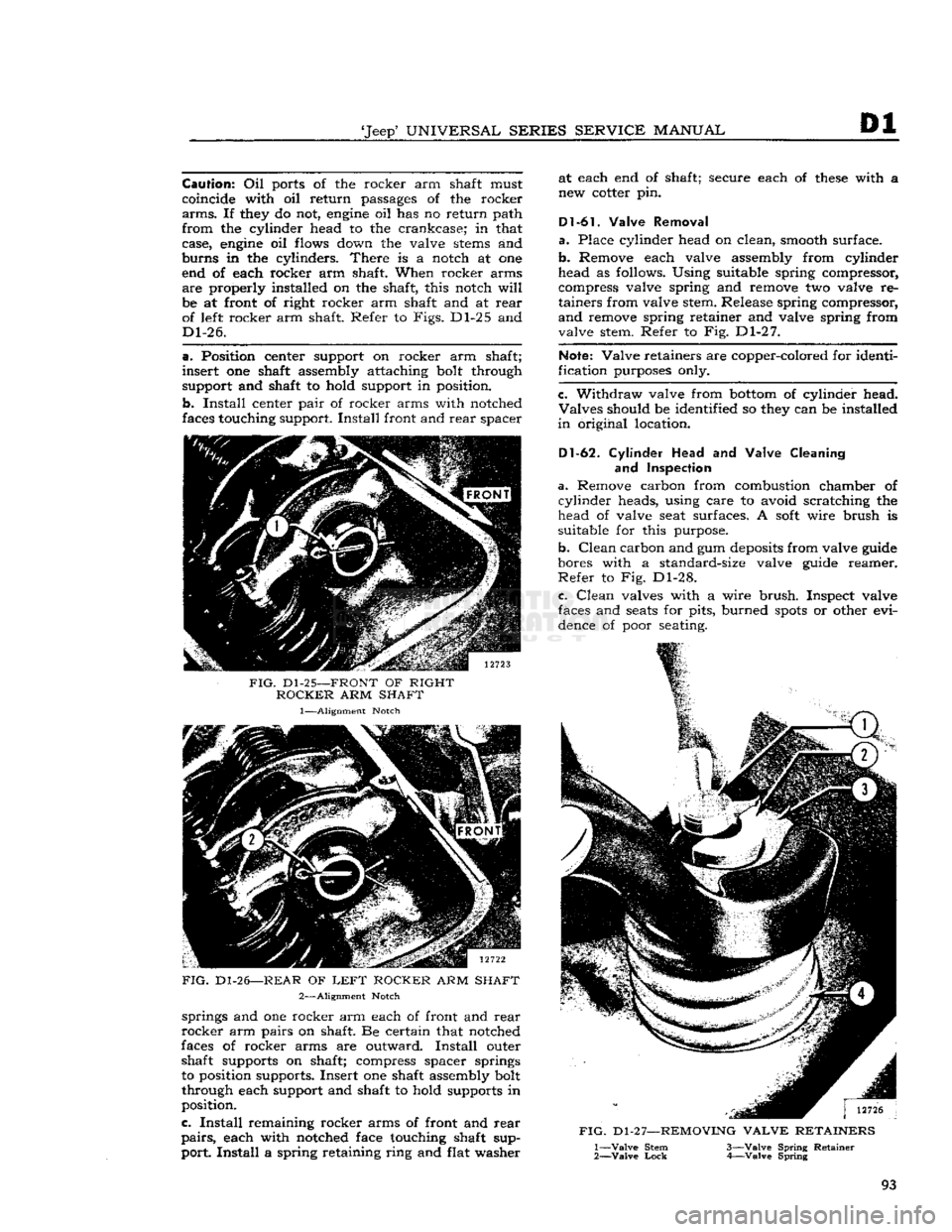
Oil ports of the rocker arm shaft must
coincide with oil return passages of the rocker
arms.
If they do not,
engine
oil has no return path
from
the cylinder head to the crankcase; in that
case,
engine
oil flows down the valve
stems
and
burns
in the cylinders.
There
is a notch at one end of each rocker arm shaft. When rocker arms
are
properly installed on the shaft, this notch
will
be at front of right rocker arm shaft and at
rear
of left rocker arm shaft. Refer to
Figs.
Dl-25 and
Dl-26.
a.
Position center support on rocker arm shaft;
insert
one shaft assembly attaching bolt through
support and shaft to hold support in position.
b.
Install
center
pair
of rocker arms with notched
faces touching support.
Install
front and
rear
spacer
FIG.
Dl-25—FRONT
OF RIGHT
ROCKER
ARM SHAFT
1—Alignment Notch
FIG.
Dl-26—REAR OF
LEFT
ROCKER
ARM SHAFT 2—Alignment Notch springs and one rocker arm each of front and
rear
rocker
arm pairs on shaft. Be certain that notched
faces of rocker arms are outward.
Install
outer shaft supports on shaft; compress spacer springs
to position supports. Insert one shaft assembly bolt
through each support and shaft to hold supports in
position.
c.
Install
remaining rocker arms of front and
rear
pairs,
each with notched face touching shaft sup
port.
Install
a spring retaining ring and flat washer at each end of shaft; secure each of
these
with a
new cotter pin.
D1 -61.
Valve Removal
a.
Place cylinder head on clean, smooth surface.
b.
Remove each valve assembly from cylinder
head as follows. Using suitable spring compressor, compress valve spring and remove two valve re
tainers
from valve stem. Release spring compressor,
and
remove spring retainer and valve spring from
valve stem. Refer to Fig. Dl-27.
Note:
Valve retainers are copper-colored for identi
fication purposes only.
c.
Withdraw valve from
bottom
of cylinder head.
Valves
should be identified so they can be installed
in
original location.
D1-62.
Cylinder
Head and Valve Cleaning
and
Inspection
a.
Remove carbon from combustion chamber of
cylinder
heads, using care to avoid scratching the head of valve seat surfaces. A
soft
wire brush is
suitable for this purpose.
b.
Clean
carbon and gum
deposits
from valve guide
bores with a standard-size valve guide reamer.
Refer
to Fig. Dl-28.
c.
Clean
valves with a wire
brush.
Inspect valve
faces and
seats
for pits, burned
spots
or other evi dence of poor seating.
FIG.
D1 -2 7—REMOVING
VALVE
RETAINERS
1—
Valve
Stem 3—Valve Spring Retainer
2—
Valve
Lock
4—Valve Spring
93
Page 97 of 376
'Jeep'
UNIVERSAL
SERIES SERVICE
MANUAL
Dl
size have
been
selected. If necessary, check or
select
connecting rod bearings as described in Par. Dl-49.
Note:
When a piston and connecting rod assembly
is properly installed, the oil spurt
hole
in the con necting rod
will
face the camshaft. The rib on the
edge
of the bearing cap
will
be on the same side
as the conical
boss
on the connecting rod web;
these
marks (rib and boss)
will
be toward the other
connecting rod on the same crankpin. The notch
on the piston
will
face the front of the
engine.
a.
Be certain that cylinder bores, pistons, connect
ing rod bearings and crankshaft journals are absolutely clean. Coat all bearing surfaces with
engine
oil.
b. Before installing a piston and connecting rod as
sembly into its bore, rotate the crankshaft so that
the corresponding crankpin is moved downward, away from the cylinder bore.
c. Remove bearing cap from connecting rod. With
upper bearing half seated in connecting rod, install connecting rod guides. These
guides
hold the upper
bearing half in place and prevent damage to the
crankshaft
crankpin during installation of the con
necting rod and piston assembly.
d.
Be certain that the gap in the oil ring rails faces
upward,
toward center of
engine.
Gaps of the com
pression rings shall not be aligned with each other
or
with the oil ring
rails.
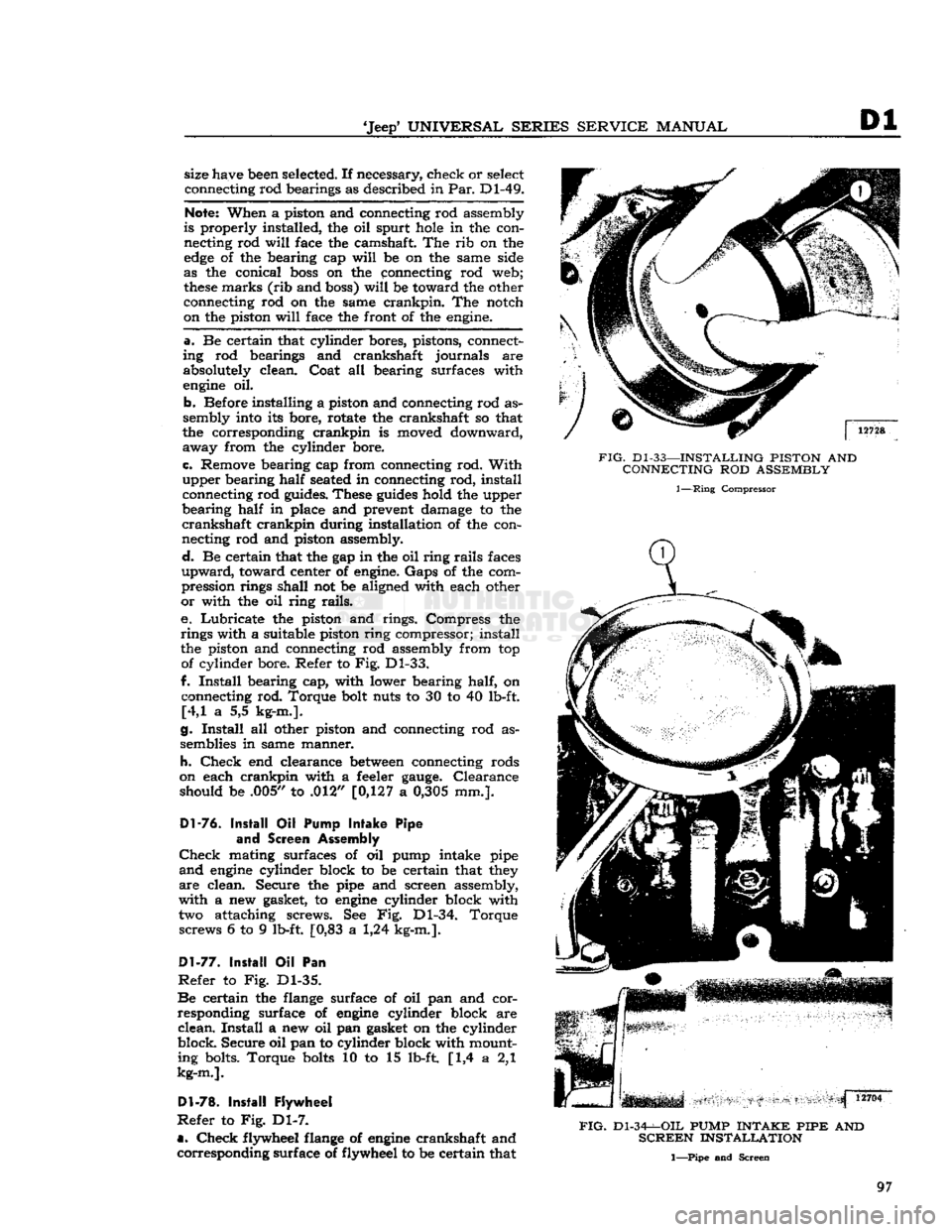
e. Lubricate the piston and rings. Compress the
rings with a suitable piston ring compressor; install
the piston and connecting rod assembly from top of cylinder bore. Refer to Fig. Dl-33.
f.
Install
bearing cap, with lower bearing half, on connecting rod. Torque bolt nuts to 30 to 40 lb-ft. [4,1 a 5,5 kg-m.].
g.
Install
all other piston and connecting rod as
semblies in same manner.
h.
Check
end clearance
between
connecting rods
on each crankpin with a feeler
gauge.
Clearance should be .005,/ to .012" [0,127 a
0,305
mm.].
Dl-76.
Install
Oil
Pump
Intake
Pipe
and
Screen Assembly
Check
mating surfaces of oil pump intake pipe
and
engine
cylinder block to be certain that they
are
clean. Secure the pipe and screen assembly,
with a new gasket, to
engine
cylinder block with two attaching screws. See Fig. Dl-34. Torque screws 6 to 9 lb-ft. [0,83 a 1,24 kg-m.].
Dl-77.
Install
Oil Pan
Refer
to Fig. Dl-35.
Be
certain the flange surface of oil pan and cor
responding surface of
engine
cylinder block are
clean.
Install
a new oil pan gasket on the cylinder
block.
Secure
oil pan to cylinder block with mount ing bolts. Torque
bolts
10 to 15 lb-ft [1,4 a 2,1
kg-m.].
Dl-78.
Install
Flywheel
Refer
to Fig. Dl-7.
a.
Check
flywheel flange of
engine
crankshaft and corresponding surface of flywheel to
be
certain that
FIG.
Dl-33—INSTALLING
PISTON
AND
CONNECTING
ROD
ASSEMBLY
1—Ring
Compressor
FIG.
Dl-34-^-OIL
PUMP
INTAKE PIPE
AND
SCREEN
INSTALLATION
1—Pipe and Screen
97
Page 99 of 376
'Jeep'
UNIVERSAL SERIES SERVICE
MANUAL
Dl
both are clean. Any foreign material on either of
these
surfaces
will
cause flywheel run out and en
gine
vibration. Position flywheel to crankshaft and
secure with six mounting bolts. Torque mounting
bolts
50 to 65 lb-ft. [6,91 a 8,98 kg-m.].
Note:
Flywheel mounting
bolts
are unevenly
spaced so that flywheel can be installed in only
one position.
This
assures correct balance of fly
wheel and crankshaft.
b.
Mount a
dial
indicator on flywheel housing
flange of cylinder block and index its plunger to
the flywheel surface. Measure flywheel run out.
Maximum
allowable run out is .015"
[0,381
mm.].
Dl-82.
Install
Cylinder
Head Assembly
Refer
to Fig. Dl-9.
a.
Wipe cylinder head face of
engine
cylinder
block, and be certain no foreign material has fallen
into the cylinder bores, bolt holes, or in the valve
lifter
area.
It is
good
practice to clean out bolt
holes
with compressed air.
b.
Install
a new cylinder head gasket on the
cylin
der
block. Dowels in the block
will
hold the gasket
in
position. Always handle gaskets carefully to
avoid
kinking or damage to the surface treatment
of the gasket. Apply Perfect Seal Aerosol
Spray
Sealer
Part
No.
994757
on cylinder head gaskets.
Dl-79.
Install
Clutch
and Flywheel Housing
a.
Note
marks made on clutch assembly and fly
wheel during
engine
disassembly. Position clutch
assembly to flywheel, according to
marks,
and
fasten
loosely
with six attaching bolts. Torque
bolts
in rotation, one
turn
at a time, to 30 to 40 lb-ft. [4,1 a 5,5 kg-m.].
b.
Engage fork of clutch linkage to clutch and
position flywheel housing to
engine
cylinder block.
Secure
housing to block with six mounting bolts.
Torque
bolts
30 to 40 lb-ft. [4,1 a 5,5 kg-m.].
D1-80.
Install
Camshaft
Insert
camshaft into camshaft bearings of
engine
cylinder
block carefully to avoid damage to bear
ing surfaces. Make certain camshaft journals are
properly
seated in bearings.
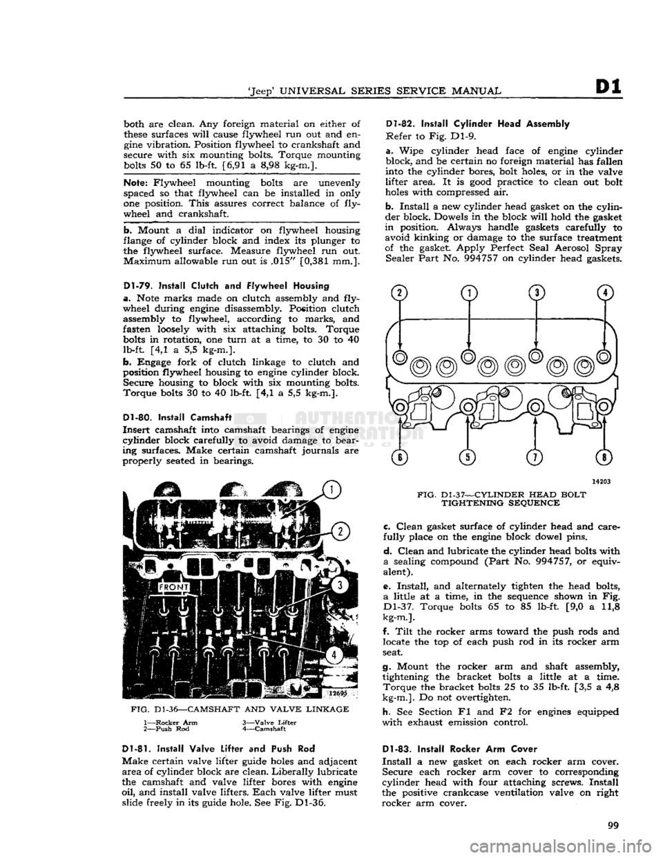
12695
FIG.
D1-36—CAMSHAFT
AND
VALVE LINKAGE
1—
Rocker
Arm
2—
Push
Rod 3—
Valve
Lifter
4—
Camshaft
14203
FIG.
Dl-37—CYLINDER
HEAD
BOLT TIGHTENING SEQUENCE c.
Clean
gasket surface of cylinder head and care
fully
place on the
engine
block dowel pins.
d.
Clean
and lubricate the cylinder head
bolts
with
a
sealing compound
(Part
No. 994757, or equiv
alent).
e.
Install,
and alternately tighten the head bolts,
a
little at a time, in the sequence shown in Fig.
Dl-37.
Torque
bolts
65 to 85 lb-ft. [9,0 a 11,8
kg-m.].
f.
Tilt
the rocker arms toward the push rods and locate the top of each push rod in its rocker arm
seat.
g.
Mount the rocker arm and shaft assembly, tightening the bracket
bolts
a little at a time.
Torque
the bracket
bolts
25 to 35 lb-ft. [3,5 a 4,8
kg-m.].
Do not overtighten.
h.
See Section Fl and F2 for
engines
equipped
with
exhaust emission control.
D1-81.
Install
Valve Lifter
and Push Rod
Make
certain valve lifter guide
holes
and adjacent
area
of cylinder block are clean.
Liberally
lubricate
the camshaft and valve lifter bores with
engine
oil,
and install valve lifters.
Each
valve lifter must slide freely in its guide hole. See Fig. Dl-36.
Dl-83.
Install
Rocker Arm Cover
Install
a new gasket on each rocker arm cover.
Secure
each rocker arm cover to corresponding
cylinder
head with four attaching screws.
Install
the positive crankcase ventilation valve on right
rocker
arm cover. 99
Page 100 of 376
Dl
DAUNTLESS
V-6
ENGINE
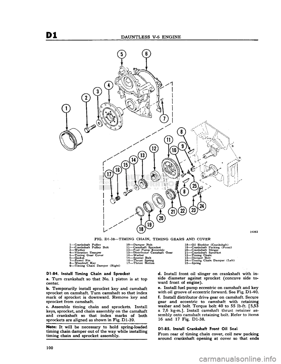
14262
FIG.
D1-38—TIMING
CHAIN,
TIMING
GEARS
AND
COVER
1—
Crankshaft
Pulley
2—
Crankshaft
Pulley Bolt
3—
Washer
4—
Vibration
Damper 5—
Timing
Gear
Cover
6—
Gasket
7—
Dowel
Pin
g—Woodruff Key
9—Timing
Chain
Damper (Right) 10—
Damper
Bolt
11—
Camshaft
Sprocket
12—
Fuel
Pump
Eccentric
13—
Distributor
Camshaft
Gear
14—
Washer
15—
Special
Bolt 16—
-Thrust
Spring
17—
Thrust
Button 18—
Oil
Shedder
(Crankshaft)
19—
-Crankshaft
Packing
(Front)
20—
-Crankshaft
Slinger •
21—
Crankshaft
Sprocket
22—
Timing
Chain
23—
Damper
Bolt .
2
A
Timing
Chain
Damper
(Left)
25
Spring
D1-84.
Install Timing Chain
and
Sprocket
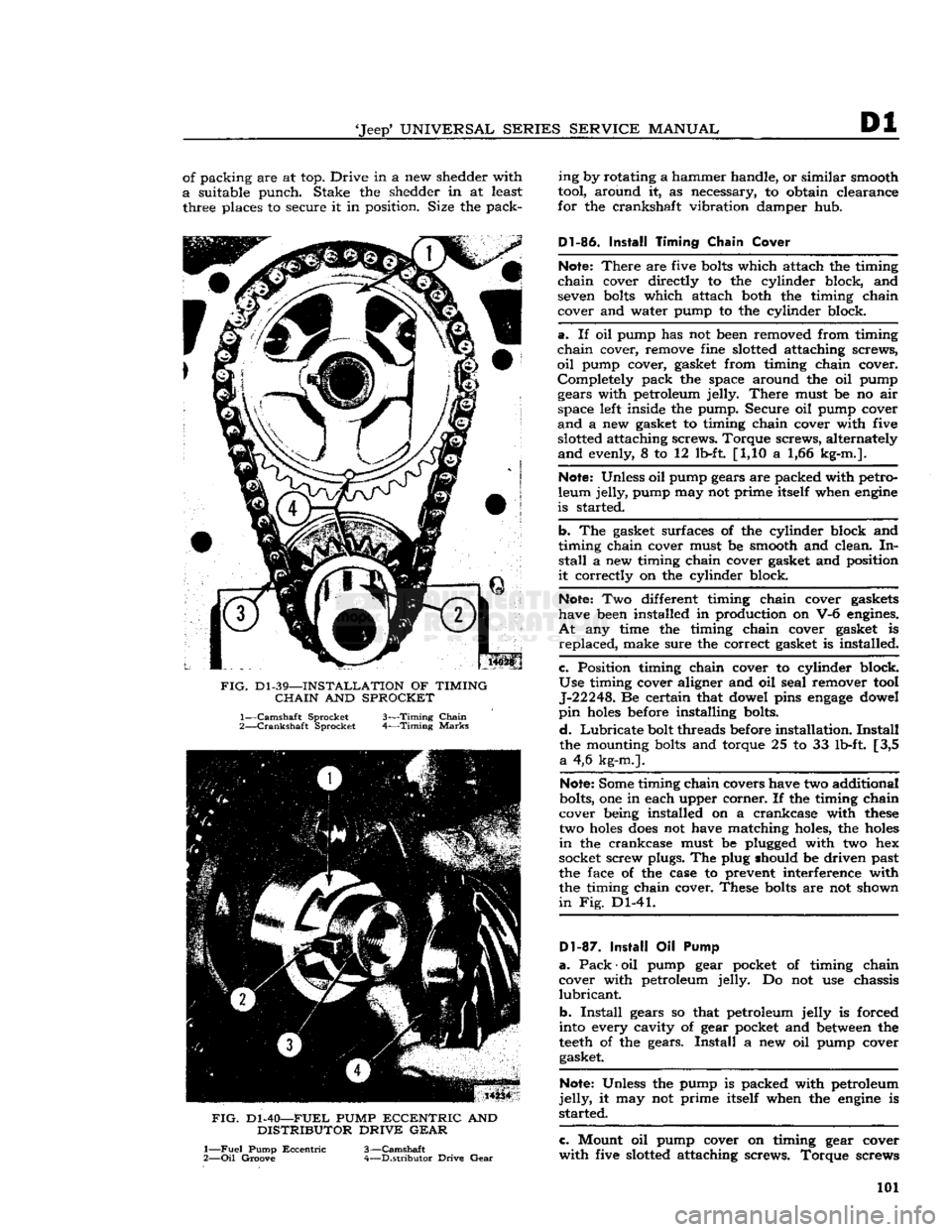
a.
Turn
crankshaft so that No. 1 piston is at top
center.
b.
Temporarily install sprocket key and camshaft
sprocket on camshaft.
Turn
camshaft so that index
mark
of sprocket is downward. Remove key and sprocket from camshaft.
c.
Assemble timing chain and sprockets.
Install
keys, sprocket, and chain assembly on the camshaft
and
crankshaft so that index marks of both sprockets are aligned as shown in
Fig.
Dl-39.
Note:
It
will
be necessary to hold spring-loaded
timing chain damper out of the way while installing
timing chain and sprocket assembly.
d.
Install
front oil slinger on crankshaft with in
side diameter against sprocket (concave side to
ward
front of engine).
e.
Install
fuel pump eccentric on camshaft and key
with
oil
groove
of eccentric forward. See
Fig.
Dl-40.
f.
Install
distributor drive gear on camshaft. Secure gear and eccentric to camshaft with retaining
washer and bolt. Torque
bolt
40 to 55 lb-ft. [5,53
a
7,6 kg-m.].
Install
camshaft thrust retainer as
sembly
onto
camshaft retaining bolt. Refer to
items
16 and 17 Fig. Dl-38.
Dl-85.
Install Crankshaft Front
Oil
Seal
From
rear
of timing chain cover, coil new packing
around
crankshaft opening at cover so that
ends
100
Page 101 of 376
'Jeep*
UNIVERSAL
SERIES SERVICE
MANUAL
Dl
of packing are at top. Drive in a new shedder with
a
suitable punch. Stake the shedder in at least three places to secure it in position. Size the pack-
FIG.
Dl-39—INSTALLATION
OF
TIMING
CHAIN
AND
SPROCKET
1—
Camshaft
Sprocket 3—Timing
Chain
2—
Crankshaft
Sprocket 4—Timing
Marks
FIG.
Dl-40—FUEL
PUMP
ECCENTRIC
AND
DISTRIBUTOR
DRIVE GEAR
1—
Fuel
Pump
Eccentric
3—Camshaft
2—
Oil
Groove 4—Distributor Drive
Gear
ing by rotating a hammer handle, or similar smooth
tool, around it, as necessary, to obtain clearance
for the crankshaft vibration damper hub.
Dl-86.
Install
Timing
Chain
Cover
Note:
There
are five
bolts
which attach the timing
chain
cover directly to the cylinder block, and seven
bolts
which attach both the timing chain
cover and water pump to the cylinder block.
a.
If oil pump has not been removed from timing
chain
cover, remove fine slotted attaching screws,
oil
pump cover, gasket from timing chain cover. Completely pack the space around the oil pump gears with petroleum jelly.
There
must be no air
space left inside the pump. Secure oil pump cover
and
a new gasket to timing chain cover with five slotted attaching screws. Torque screws, alternately
and
evenly, 8 to 12 lb-ft [1,10 a 1,66 kg-m.].
Note:
Unless oil pump gears are packed with petro
leum jelly, pump may not prime itself when
engine
is started.
b.
The gasket surfaces of the cylinder block and
timing chain cover must be smooth and clean. In
stall
a new timing chain cover gasket and position
it
correctly on the cylinder block.
Note:
Two different timing chain cover gaskets
have been installed in production on V-6 engines.
At
any time the timing chain cover gasket is
replaced,
make sure the correct gasket is installed.
c.
Position timing chain cover to cylinder block.
Use
timing cover aligner and oil seal remover tool J-22248. Be certain that dowel pins
engage
dowel
pin
holes
before installing bolts.
d.
Lubricate
bolt threads before installation.
Install
the mounting
bolts
and torque 25 to 33 lb-ft. [3,5
a
4,6 kg-m.].
Note:
Some timing chain covers have two additional
bolts, one in each upper corner. If the timing chain
cover being installed on a crankcase with
these
two
holes
does
not have matching holes, the
holes
in
the crankcase must be plugged with two hex
socket screw plugs. The plug should be driven past
the face of the case to prevent interference with the timing chain cover. These
bolts
are not shown
in
Fig. Dl-41.
D1-87.
Install
Oil Pump
a.
Pack
•
oil pump gear pocket of timing chain
cover with petroleum jelly. Do not use chassis
lubricant.
b.
Install
gears so that petroleum jelly is forced
into every cavity of gear pocket and
between
the
teeth
of the gears.
Install
a new oil pump cover gasket.
Note:
Unless the pump is packed with petroleum
jelly,
it may not prime itself when the
engine
is
started.
c.
Mount oil pump cover on timing gear cover
with
five slotted attaching screws. Torque screws 101
Page 102 of 376
![JEEP CJ 1953 Owners Manual
Dl
DAUNTLESS
V-6
ENGINE
FIG.
Dl-41—WATER
PUMP
AND
TIMING CHAIN COVER BOLT LOCATION
Cover
Bolts
alternately and evenly 8 to 12 lb-ft. [1,10 a 1,66
kg-m.].
Dl-88.
Install
Cranksh JEEP CJ 1953 Owners Manual
Dl
DAUNTLESS
V-6
ENGINE
FIG.
Dl-41—WATER
PUMP
AND
TIMING CHAIN COVER BOLT LOCATION
Cover
Bolts
alternately and evenly 8 to 12 lb-ft. [1,10 a 1,66
kg-m.].
Dl-88.
Install
Cranksh](/img/16/57040/w960_57040-101.png)
Dl
DAUNTLESS
V-6
ENGINE
FIG.
Dl-41—WATER
PUMP
AND
TIMING CHAIN COVER BOLT LOCATION
Cover
Bolts
alternately and evenly 8 to 12 lb-ft. [1,10 a 1,66
kg-m.].
Dl-88.
Install
Crankshaft
Vibration
Damper
a.
Lubricate
the vibration damper hub
before
in
stallation to prevent
damage
to the crankshaft
front oil seal during installation and when the
engine
is first started.
b.
Install
the vibration damper on the crankshaft.
Secure it with its attaching flat washer and screw.
Torque
the screw to a minimum of 140 lb-ft.
[19,35
kg-m.].
Dl-89.
Install
Crankshaft Pulley
Secure the crankshaft pulley to the crankshaft
vibration
damper with six screws. Torque screws 18 to 25 lb-ft. [2,5 a 3,4 kg-m.].
Dl-90.
Install
Oil
Level
Dipstick
Insert
oil level dipstick
into
the dipstick tube.
Dl-91.
Install
Oil
Pressure Sending Unit
Install
oil pressure sending unit in cylinder block.
Connect electrical wiring harness to unit.
Dl-92.
Install Starting Motor
Secure starting motor and
solenoid
assembly to
the flywheel housing and cylinder block with two attaching screws. Torque screw, which attaches this
assembly to the flywheel housing, 30 to 40 lb-ft. [4,1 a 5,5 kg-m.]. Torque screw, which attaches
bracket
to cylinder block, 10 to 12 lb-ft. [1,4 a 1,7 kg-m.].
Dl-93.
Install
Oil
Filter
Install
a new oil filter
element
at oil filter nipple,
at
left
side
of timing chain cover. Torque 10 to 15 lb-ft. [1,38 a 2,07 kg-m.].
D1-94. Install Water Pump
Be
certain that mating surfaces of the water pump
and
timing chain cover are clean.
Install
a new
gasket
on the pump flange. Secure the pump and
alternator adjustment bracket to the cover with
nine attaching bolts. Torque
bolts
6 to 8 lb-ft. [0,83 a 1,10 kg-m.]. Refer to Fig. Dl-41.
D1-9S.
Install
Cooling Fan
Secure the cooling fan, fan hub, and fan drive
pulley to the water pump shaft
flange
with four
attaching screws. Torque screws 17 to 23 lb-ft. [2,35 a 3,18 kg-m.].
Dl-96.
Install
Alternator
and Fan
Belt
Mount the alternator and bracket assembly on
right
cylinder head with two attaching screws.
Torque
screws 30 to 40 lb-ft. [4,1 a 5,5 kg-m.].
Fasten
the alternator
loosely
to its adjustment
bracket
with attaching flat washer and nut.
Install
the fan
belt
on its pulleys. Pivot the alternator
outward,
away from cylinder block, to apply fan
belt
tension. Adjust fan
belt
tension to 80 lb. [36,2 kg.];
tighten
alternator-to-adjustment bracket
nut to secure adjustment
setting.
Connect wiring
harness to alternator.
Dl-97.
Install
Fuel Pump
Install
two mounting
bolts
and new
gasket
on
flange
of fuel pump. Secure pump to timing chain cover with screws; torque screws 17 to 23 lb-ft. [2,35 a 3,8 kg-m.]. Connect
output
fuel line to
pump.
Dl-98.
Install Exhaust Manifold
Secure each of two exhaust manifolds to corre
sponding cylinder head with five attaching screws,
and
one nut. Torque screws and nut 15 to 20 lb-ft. [2,07 a 2,8 kg-m.]. See Fig. Dl-42.
Dl-99.
Install Distributor
Insert
distributor drive gear
into
distributor mount-
FIG.
Dl-42—EXHAUST
MANIFOLD INSTALLATION
1—Torque
Bolts—15
to 20
lb-ft.
[2,07 a 2,8
kg-m.]
102
Page 104 of 376
Dl
DAUNTLESS
V-6
ENGINE
e.
Connect electrical wiring harness to coolant
temperature sending unit. Connect two distributor leads to ignition coil. Connect fuel line
between
fuel pump and carburetor, vacuum
hose
between
distributor and carburetor, and crankcase vent
hose
to intake manifold
below
rear
of carburetor.
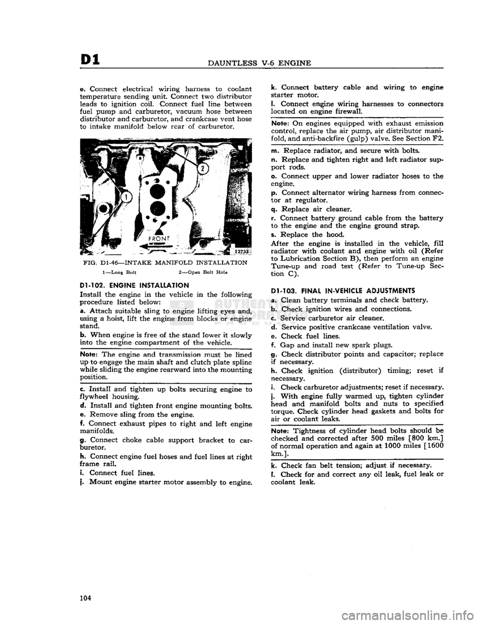
FIG.
D1-46—-INTAKE
MANIFOLD
INSTALLATION
1—Long Bolt 2—Open Bolt Hole
Dl-102.
ENGINE INSTALLATION
Install
the
engine
in the vehicle in the following
procedure listed
below:
a.
Attach suitable sling to
engine
lifting
eyes
and,
using a hoist, lift the
engine
from blocks or
engine
stand.
b. When
engine
is free of the stand lower it slowly
into
the
engine
compartment of the vehicle.
Note:
The
engine
and transmission must be lined
up to
engage
the main shaft and clutch plate spline
while sliding the
engine
rearward
into
the mounting
position.
c.
Install
and tighten up
bolts
securing
engine
to
flywheel housing.
d.
Install
and tighten front
engine
mounting bolts.
e.
Remove sling from the
engine.
I.
Connect exhaust pipes to right and
left
engine
manifolds.
g. Connect choke cable support bracket to
car
buretor.
h.
Connect
engine
fuel
hoses
and fuel lines at right
frame
rail.
I.
Connect fuel lines.
j.
Mount
engine
starter motor assembly to
engine.
k.
Connect battery cable and wiring to
engine
starter
motor.
I.
Connect
engine
wiring harnesses to connectors
located on
engine
firewall.
Note:
On
engines
equipped with exhaust emission
control, replace the air pump, air distributor mani
fold, and anti-backfire (gulp) valve. See Section F2.
m. Replace radiator, and secure with bolts,
n.
Replace and tighten right and
left
radiator sup
port rods.
0. Connect upper and lower radiator
hoses
to the
engine.
p. Connect alternator wiring harness from connec
tor at regulator,
q.
Replace air cleaner.
r.
Connect battery ground cable from the battery
to the
engine
and the
engine
ground strap,
s.
Replace the hood.
After
the
engine
is installed in the vehicle,
fill
radiator
with coolant and
engine
with oil (Refer to
Lubrication
Section B), then perform an
engine
Tune-up
and road
test
(Refer to Tune-up Sec
tion C).
Dl-103.
FINAL IN-VEHICLE ADJUSTMENTS
a.
Clean
battery terminals and check battery.
b.
Check
ignition wires and connections.
c. Service carburetor air cleaner.
d.
Service positive crankcase ventilation valve.
e.
Check
fuel lines.
f. Gap and install new
spark
plugs.
g.
Check
distributor
points
and capacitor; replace
if
necessary.
h.
Check
ignition (distributor) timing; reset if
necessary. 1.
Check
carburetor adjustments; reset if necessary,
j.
With
engine
fully warmed up, tighten cylinder
head and manifold
bolts
and nuts to specified
torque.
Check
cylinder head
gaskets
and
bolts
for
air
or coolant leaks.
Note:
Tightness of cylinder head
bolts
should be
checked and corrected after 500 miles [800 km.]
of normal operation and again at 1000 miles [1600
km.].
k.
Check
fan belt tension; adjust if necessary.
I.
Check
for and correct any oil leak, fuel leak or
coolant leak. 104
Page 118 of 376
E
FUEL
SYSTEM
Note:
Do not remove pressed-in parts such as
nozzle, pump jet, or antipercolator air bleed.
j.
Remove body flange attaching screws, body flange assembly, and gasket.
k.
Remove idle-adjustment screw, spring, idle
port
rivet, throttle lever assembly, washer, fast
idle arm, throttle plate screws, throttle plate, and throttle shaft.
1. Remove throttle shaft seal by prying out seal
retainer.
Note:
Do not remove pressed-in vacuum passage
orifice.
m.
Remove choke valve screws and choke valve.
Unhook
choke spring and slide shaft from housing,
n.
Wash all parts in carburetor cleaning solution
and
blow out passages with compressed air. Do not immerse diaphragm or seals in cleaning solution.
Inspect
all parts for wear or damage. Always use
new gaskets when reassembling.
E-22.
Carburetor
Reassembly
•
Refer to Fig. E-13.
To
expedite
reassembly, it is advisable to group all
related
parts by the circuit to which they belong.
a.
Install
throttle shaft seal and retainer in flange casting.
b.
Install
fast-idle
arm,
washer, and lever assembly
on throttle shaft. Slide shaft into place and install throttle valve.
c.
Install
idle port rivet plug and idle adjusting
screw
and spring.
d.
Attach flange assembly to body casting. Use new gasket.
e.
Install
low-speed jet assembly.
f.
Early
production models install pump intake
strainer
in pump diaphragm housing and carefully
press into recess.
Note:
If strainer is even slightly damaged, a new
one must be installed.
g.
Install
pump diaphragm assembly in diaphragm housing.
Then,
install pump diaphragm spring
(lower)
and retainer.
h.
Install
pump lifter
link,
metering rod
arm,
upper
pump spring, and retainer.
I.
Install
metering rod jet.
Note:
No gasket is used with this jet.
j.
Install
diaphragm housing attaching screws in
the diaphragm housing, making sure that the
edges
of the diaphragm are not wrinkled.
Lower
into place and tighten screws evenly and securely,
k.
Install
throttle shaft seal, dust seal washer, and
shaft seal spring.
I.
Install
pump connector
link
in the throttle arm
assembly.
Install
throttle shaft arm assembly on
throttle shaft guiding connector
link
in pump lifter
link
hole.
CAUTION:
Linkage
must not bind in any throttle
position. If binding occurs,
loosen
clamp screw in
throttle arm, adjust slightly, then retighten screw.
m.
Install
pump check disc, disc retainer, and lock
ring.
n.
Install
metering rod and pin spring. Connect
metering rod spring.
o.
Check
and if necessary correct meter ing rod adjustment. Follow procedure of
Par.
E-16.
p.
Install
needle
seat and gasket assembly, needle,
float
and
float pin. The
stop
shoulder on the float
pin
must be on the side away from the bore of
the carburetor.
q.
Set float level to specifications. Follow pro cedure of
Par.
E-12.
r.
Install
air horn gasket and air horn assembly.
Install
attaching screws, lock washers, and choke
tube clamp assembly. Tighten center screws first,
s. Slide choke shaft and lever assembly into place
and
connect choke lever
spring.
Install
choke valve.
Center
the valve by tapping lightly, then hold in
place with fingers when tightening screws,
t.
Install
fast-idle connector rod with
offset
portion
of rod on top and pin spring on outside.
Install
fast-idle connecting rod spring.
E-23.
Correcting Acceleration
Flat
Spot
Early
production
Carburetor
Models 938-S, 938-
SA,
938-SC
Inasmuch
as a flat
spot
on acceleration or low speed
stumble can
come
from causes other than
car
buretor
malfunction, it is recommended that
engine
tuning be thoroughly checked before attempting
any
actual carburetor work. Make sure that
ignition, compression, and timing are correct and
that fuel pump is supplying enough gas. Also, the F-head
engine
employs a water-heated intake
manifold.
Proper vaporization of the fuel depends
on correct intake manifold temperature. Since this
temperature is controlled by the cooling system
thermostat, include an operational check of the
thermostat when diagnosing the stumble. Operating
temperatures consistently below
155°F.
can cause stumble.
If
the stumble persists, a
YF-938-S,
YF-938-SA,
or
YF-938-SC
carburetor can be converted to a
YF-938-SD
carburetor by installing Special Kit
924161, consisting of a pump discharge check
needle, a metering rod, and a metering rod jet. If this kit is installed, the pump discharge check
needle
replaces the original
ball,
weight, and re
tainer
and the small wire-type retainer used with
the
ball
check assembly must not be reinstalled.
When
installing the kit, check the size of the pump discharge jet, No. 2, Fig. E-14.
Early
production
YF-938S
and
YF-938SA
carburetors have a .025" [0,635 mm.] jet installed. If the carburetor being
converted has a .025" jet it must be opened up to .031" [0,787 mm.] by running a No. 68
drill
through
the jet as shown in
Fig.
E-14.
The jet must be drilled
as it is a pressed in part and cannot be replaced.
Upon
completing the installation of the conversion
kit,
mark
or tag the carburetor to indicate that it
is a
YF-938SD.
118
Page 123 of 376
'Jeep9
UNIVERSAL
SERIES
SERVICE
MANUAL
E
exterior moving parts of a carburetor are
often
responsible for unsatisfactory performance.
For
this
reason,
efficient carburetion depends upon careful cleaning and inspection while servicing.
a.
Thoroughly clean carburetor castings and metal
parts
in carburetor cleaning solvent.
Caution:
Accelerator pump plunger and any fiber
or
rubber parts should never be immersed in
car
buretor
cleaner. Wash pump plunger in cleaning
solvent.
b.
Blow out all passages in the castings with com
pressed air. Dry all parts with compressed air.
Make
sure all jets and passages are clean. Do
not use wire to clean fuel passages or air bleeds.
c.
Check
inlet valve
needle
and seat for wear. If
wear
is noted, the assembly must be replaced.
d.
Check
float hinge pin for wear and check float
for damage.
e.
Check
throttle and choke shaft bores for wear
and
out-of-round.
f. Inspect idle mixture adjustment
needles
for
burrs
or
grooves; replace if damaged.
g. Inspect cup of accelerator pump plunger; re
place if damaged, worn, or hardened. Inspect pump
well
in bowl for wear or scoring.
h.
Check
filter screens for
dirt
or lint.
Clean,
and
if
they remain
clogged,
replace.
i.
If for any reason parts have
become
loose
or
damaged in the cluster assembly, the assembly
must be replaced.
Note:
Use ijew gaskets whenever the carburetor
is disassembled.
E-37.
Throttle Body Assembly
a.
Install
idle mixture adjustment
needles
and
springs in throttle body. Tighten finger-tight, then
unthread
one
turn
as a preliminary adjustment
setting.
Caution:
Do not force idle mixture adjustment
needles
against
seats
or damage may result.
b.
Invert
fuel bowl body and place new throttle
body gasket on bowl. Fasten throttle body to bowl
body with three screws and lockwashers; tighten
securely.
E-38.
Fuel
Bowl Body Assembly
a.
Drop steel discharge check
tall
of accelerator
pump into discharge hole.
Install
pump discharge
spring
and T-shaped retainer. Stake retainer in
place.
Note:
Top of retainer must be flush with flat
surface
of fuel bowl body.
b.
Install
two inserts in main well. Align surface
on lip of insert with flat surface in recess on top
of main well.
Install
venturi cluster with gasket,
and
tighten mounting screws evenly and securely.
Be
certain that center screw is fitted with fiber gasket, and that a special smooth shank screw is
used.
c.
Install
two main metering jets, power valve
gasket and power valve.
d.
Install
small aluminum inlet check
ball
in ac
celerator
pump inlet at
bottom
of pump well. In
sert
pump return spring into well, and center by
pressing spring downward with finger.
e.
Install
pump inlet screen in
bottom
of fuel
bowl.
E-39.
Air
Horn Body
Assembly
a.
Install
choke lever and collar on choke shaft.
Prong
on choke lever must face away from air
horn
body and be on top of choke trip lever.
b.
Install
choke shaft and lever assembly into the
air
horn. Choke rod
hole
in the choke lever must
face fuel inlet side of carburetor.
c.
Install
choke valve plate in choke shaft so that
letters RP
will
face upward in finished carburetor.
Install
two new valve plate attaching screws, but
do not tighten securely until valve plate is centered.
To
center choke valve plate on choke shaft, hold
choke valve tightly closed, then slide choke shaft
inward
to obtain approximately .020" [0,508 mm.]
clearance
between
choke trip lever and choke lever
and
collar assembly. Tighten choke valve screws
securely,
and stake lightly in place. Choke valve
will
be perfectly free in all positions when installed
correctly.
d.
Insert
outer accelerator pump lever and shaft as sembly into air horn body, with lever pointing to
ward
choke shaft.
Install
inner pump arm, with plunger
hole
inward,
and tighten set screw securely.
Position pump plunger assembly on inner pump
arm,
with pump shaft pointing
inward,
and install
retainer.
e.
Install
needle
seat screen on inlet valve seat. In
stall
seat and gasket in air horn body. Tighten seat
securely with a wide-blade screwdriver.
f.
Install
power piston into vacuum cavity.
Lightly
stake piston retainer washer in place. Piston should
travel
freely in cavity.
g.
Install
air horn gasket on air horn body, fitting
gasket over guide pin.
h.
Attach inlet valve
needle
to float.
Carefully
position float and insert float hinge pin. Drop tang
at
rear
of float arm downward toward air horn.
i.
Install
fuel inlet fitting, if removed.
j.
With
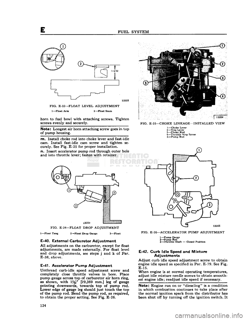
air horn assembly inverted, measure the distance from the air horn gasket to top of float
at toe \%£f [27,78 mm.] for standard carburetors
and
\%i [29,36 mm.] for exhaust emission control
equipped carburetors, as shown in Fig. E-23. Use
float level
gauge
J-5127-2. Bend float arm as re
quired
to adjust float level.
k.
With
air horn body held upright, measure dis
tance from gasket to
bottom
of float
pontoon
at outer end. Use a l7/s" [47,625 mm.] float drop
gauge.
Bend float tang, as required, to adjust float
drop.
See Fig. E-24.
I.
Carefully
place air horn body on fuel bowl
body, making certain that the accelerator pump
plunger is properly positioned in the pump well.
Lower
the cover gently, straight down; install air 123
Page 124 of 376
FUEL
SYSTEM
1-5/32
133S2
FIG.
E-23—FLOAT
LEVEL
ADJUSTMENT
l—Float
Arm 2—Float Scam
horn
to fuel bowl with attaching screws. Tighten screws evenly and securely.
Note:
Longest air horn attaching screw
goes
in top
of pump housing.
m.
Install
choke rod into choke lever and fast-idle
cam.
Install
fast-idle cam screw and tighten se
curely.
See Fig. E-25 for proper installation,
n.
Insert accelerator pump rod through outer
hole
and
into throttle lever; fasten with retainer.
A33S3
FIG. E-24—FLOAT DROP ADJUSTMENT
1—Float Tang 2—Float Drop Gauge 3—Float
E-40.
External
Carburetor
Adjustment
All
adjustments on the carburetor, except for float
adjustments, are made externally. For float level
and
drop adjustments, see
steps
j and k of Par.
E-38,
above.
E-41.
Accelerator Pump Adjustment
Unthread
curb-idle speed adjustment screw and completely
close
throttle valves in bore. Place
pump
gauge
across top of carburetor air horn ring,
as shown, with 15^" [29,369 mm.] leg of
gauge
pointing downwards, towards top of pump rod.
Lower
edge
of
gauge
leg should just touch the top
of the pump rod. Bend the pump rod, as required, to obtain the proper setting. See Fig. E-26. ]
13354
FIG.
E-25—CHOKE LINKAGE—INSTALLED VIEW 1—
Choke
Lever
2—
Trip
Lever
3—
Choke
Rod
4—
Throttle
Stop Screw 5—
Pump
Rod
13355
FIG.
E-26—ACCELERATOR
PUMP
ADJUSTMENT 1—
Pump
Gauge 2—
Pump
Rod
3—
Throttle
Shaft — Closed Position
E-42.
Curb
Idle Speed and Mixture
Adjustments
Adjust
curb idle speed adjustment screw to obtain
engine
idle speed as specified in Par. E-79. See Fig.
E-15.
When
engine
is at normal operating temperatures,
adjust
idle mixture
needle
screws to obtain smooth
est
engine
idle; readjust idle speed if necessary.
Note:
Engine run on or "dieseling" is a condition
in
which combustion continues to take place after
the normal ignition spark from the distributor has
been shut off by turning off the ignition switch. It 124