key JEEP CJ 1953 Owner's Manual
[x] Cancel search | Manufacturer: JEEP, Model Year: 1953, Model line: CJ, Model: JEEP CJ 1953Pages: 376, PDF Size: 19.96 MB
Page 189 of 376
'Jeep'
UNIVERSAL
SERIES
SERVICE
MANUAL
H
U029p 1—
Oil
Retainer
2—
Bearing
3—
-Felt
Wick
4—
Oiler
5—
Commutator
End Head
6—
Brush
Lead
Screw
7—
Lockwasher
8—
Brush
Set
9—
Brush
Spring
10—
Brush
Arm
11—
Frame
12—
Insulating
Bushing
13—
Washer
14—
Lockwasher
15—
Hex
Nut
16—
Lockwasher
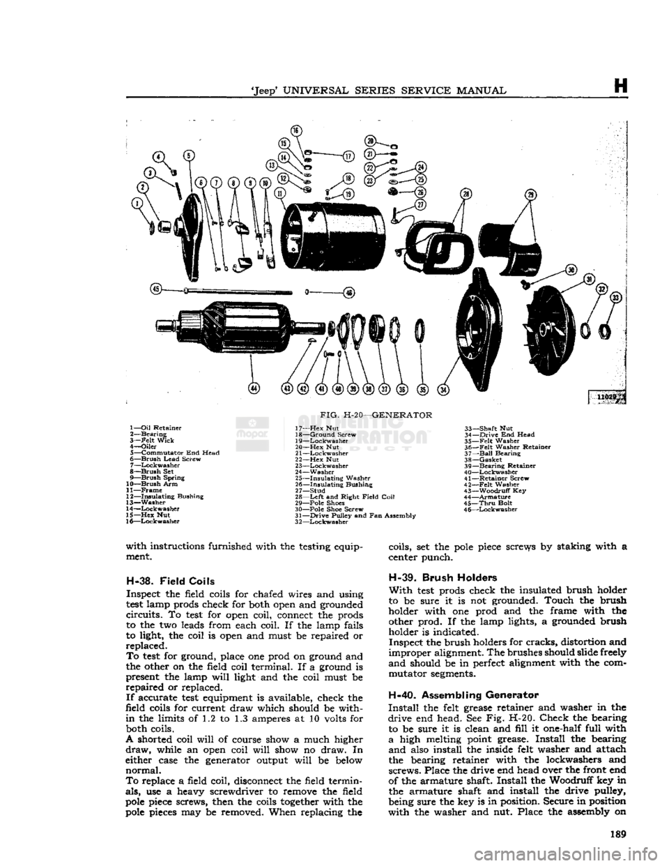
FIG.
H-20—GENERATOR
17—
Hex
Nut
18—
Ground
Screw
19—
Lockwasher
20—
Hex
Nut
21
—Lockwasher
22—
Hex
Nut
23—
Lockwasher
24—
Washer
25—
Insulating
Washer
26—
Insulating
Bushing
27—
Stud
28—
Left
and Right
Field
Coil
29— Pole Shoes
30— Pole Shoe Screw
31—
Drive
Pulley and Fan Assembly
3
2—Lockwasher
33—
Shaft
Nut
34—
Drive
End Head
35—
Felt
Washer
36—
Felt
Washer Retainer
37—
Ball
Bearing
38—
Gasket
39—
Bearing
Retainer
40—
Lockwasher
41—
Retainer
Screw
42—
-Felt
Washer
43—
Woodruff
Key
44—
Armature
45—
Thru
Bolt
4
6—Lockwasher
with
instructions furnished with the testing equip ment.
H-38.
Field
Coils
Inspect the field coils for chafed wires and using
test
lamp prods check for both open and grounded
circuits.
To
test
for open coil, connect the prods
to the two leads from each coil. If the lamp fails
to light, the coil is open and must be repaired or
replaced.
To
test
for ground, place one prod on ground and
the other on the field coil terminal. If a ground is present the lamp
will
light and the coil must be
repaired
or replaced.
If
accurate
test
equipment is available, check the
field coils for current draw which should be with
in
the limits of 1.2 to 1.3 amperes at 10 volts for both coils.
A shorted coil
will
of course show a much higher
draw,
while an open coil
will
show no draw. In
either case the generator output
will
be below
normal.
To
replace a field coil, disconnect the field termin
als,
use a heavy screwdriver to remove the field
pole
piece screws, then the coils
together
with the
pole
pieces may be removed. When replacing the coils, set the
pole
piece screws by staking with a
center punch.
H-39.
Brush
Holders
With
test
prods check the insulated brush holder
to be sure it is not grounded. Touch the brush
holder with one prod and the frame with the other prod. If the lamp lights, a grounded brush holder is indicated.
Inspect the brush holders for
cracks,
distortion and
improper
alignment. The brushes should slide freely
and
should be in perfect alignment with the com mutator
segments.
H-40.
Assembling Generator
Install
the felt grease retainer and washer in the
drive
end head. See Fig. H-20.
Check
the bearing to be sure it is clean and
fill
it one-half full with
a
high melting point grease.
Install
the bearing
and
also install the inside felt washer and attach
the bearing retainer with the lockwashers and
screws.
Place the drive end head over the front end
of the armature shaft.
Install
the Woodruff key in the armature shaft and install the drive pulley,
being sure the key is in position. Secure in position
with
the washer and nut. Place the assembly on 189
Page 196 of 376
H
ELECTRICAL
SYSTEM DC
ammeter — 0 to 60 ampere
DC
ammeter — 0 to 5 ampere
DC
voltmeter — 0 to 16 volt
Rheostat — 40 ohm capable of
handling
3 amps.
Carbon
Pile — 45 amperes
b.
Diode Rectifier Tester C-3829.
c.
12-volt DC
test
lamp.
d.
Ohmmeter of any commercial type is not absolutely necessary but can be helpful.
H-69.
Isolation Diode
Check
With
the ignition key in the off position the correct voltage at the auxiliary terminal is zero volts. If
voltage measured at auxiliary terminal is the same as voltage at output terminal, the isolation diode
is shorted. In most cases, the charge indicator lamp
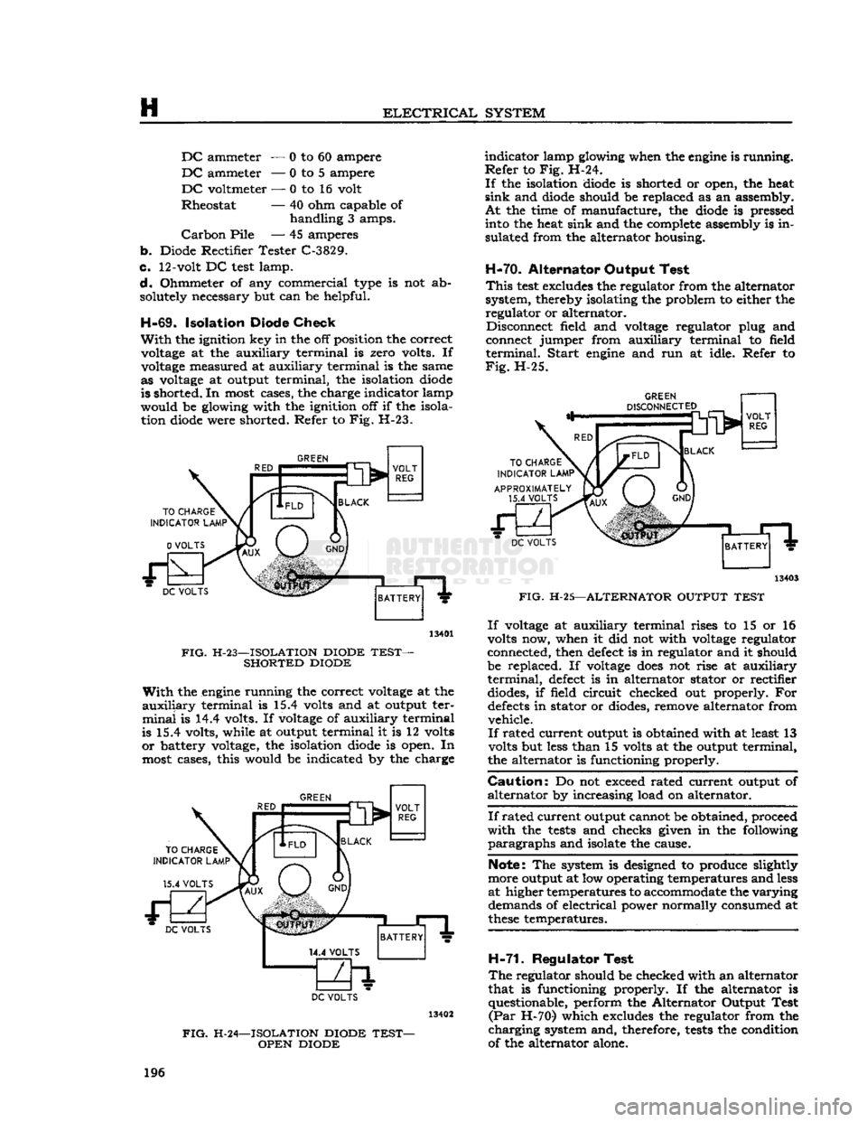
would be glowing with the ignition off if the isola tion diode were shorted. Refer to Fig. H-23.
GREEN
DC
VOLTS
13401
FIG.
H-23—ISOLATION DIODE
TEST-
SHORTED DIODE
With
the engine running the correct voltage at the
auxiliary
terminal is 15.4 volts and at output ter
minal
is 14.4 volts. If voltage of auxiliary terminal
is 15.4 volts, while at output terminal it is 12 volts
or
battery voltage, the isolation diode is open. In
most cases, this would be indicated by the charge
GREEN
TO
CHARGE
INDICATOR
LAMP1
15.4
VOLTS BLACK
VOLT
REG DC
VOLTS
BATTERY
DC
VOLTS
FIG.
H-24—ISOLATION DIODE
TEST-
OPEN DIODE
indicator
lamp glowing when the engine is running.
Refer
to Fig. H-24.
If
the isolation diode is shorted or open, the heat
sink
and diode should be replaced as an assembly.
At
the time of manufacture, the diode is pressed into the heat sink and the complete assembly is in
sulated from the alternator housing.
H-70.
Alternator Output Test
This
test
excludes the regulator from the alternator
system, thereby isolating the problem to either the regulator or alternator. Disconnect field and voltage regulator plug and
connect jumper from auxiliary terminal to field
terminal.
Start
engine and run at idle. Refer to
Fig.
H-25.
DC
VOLTS
13403
FIG.
H-25—ALTERNATOR OUTPUT
TEST
If
voltage at auxiliary terminal rises to 15 or 16
volts now, when it did not with voltage regulator
connected, then defect is in regulator and it should
be replaced. If voltage
does
not rise at auxiliary
terminal,
defect is in alternator stator or rectifier diodes, if field circuit checked out properly. For
defects
in stator or diodes, remove alternator from vehicle.
If
rated current output is obtained with at least 13
volts but less than 15 volts at the output terminal,
the alternator is functioning properly.
Caution:
Do not exceed rated current output of
alternator
by increasing load on alternator.
If
rated
current
output cannot be obtained, proceed
with
the
tests
and checks given in the following
paragraphs
and isolate the cause.
Note: The system is designed to produce slightly
more output at low operating temperatures and less
at higher temperatures to accommodate the
varying
demands of electrical power normally consumed at
these
temperatures.
H-71.
Regulator Test
The
regulator should be checked with an alternator
that is functioning properly. If the alternator is questionable, perform the Alternator Output Test
(Par
H-70) which excludes the regulator from the
charging
system and, therefore,
tests
the condition
of the alternator alone. 196
Page 197 of 376
'Jeep'
UNIVERSAL SERIES SERVICE
MANUAL
H
H-72.
Removal
and
Installation
of
Voltage Regulator
The
transistorized
voltage
regulator is a sealed unit.
It
cannot be disassembled or adjusted. If found to
be defective in any way, it must be replaced as
a
unit.
The
transistorized
voltage
regulator is mounted on
the fender dust shield by three mounting screws.
Wiring
connections to the charging circuit are made through a three-prong connector.
To
remove the regulator, disconnect the three
-
prong connector and remove the three mounting
screws.
Installation of the regulator is the reverse
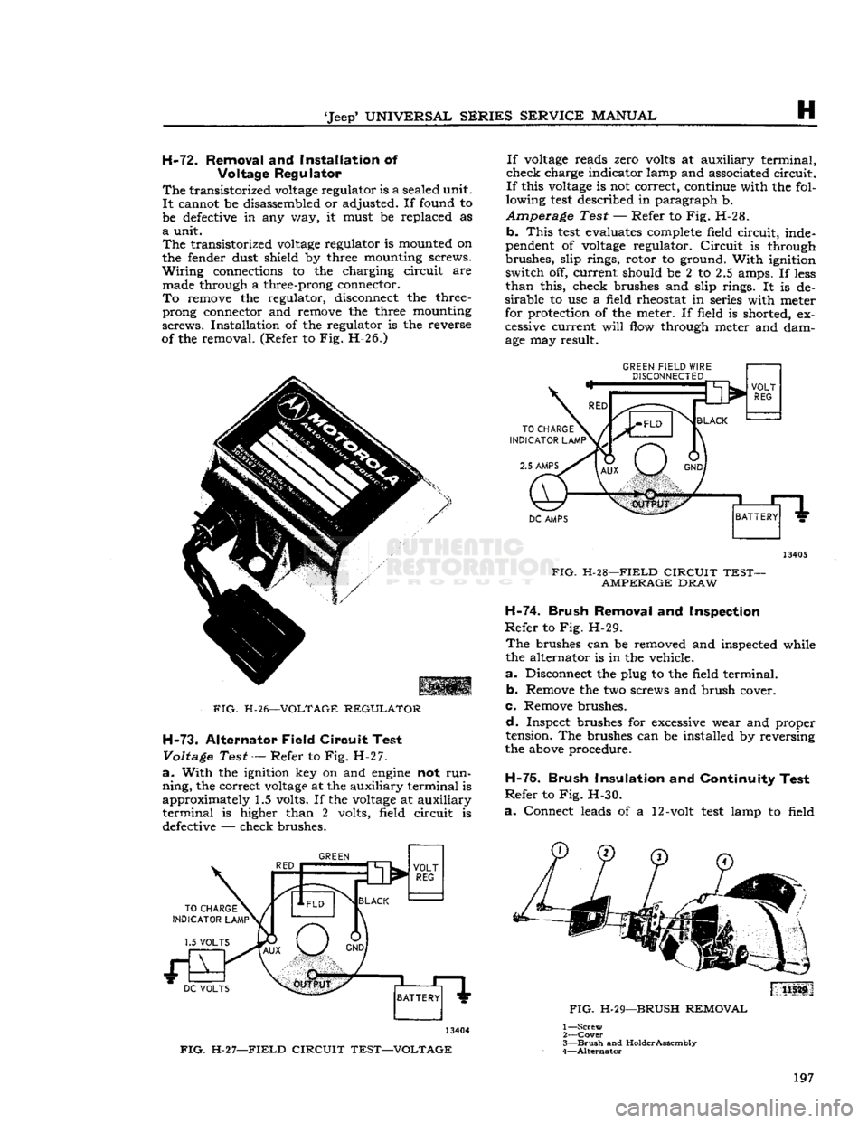
of the removal. (Refer to Fig. H-26.)
FIG.
H-26—VOLTAGE
REGULATOR
H-73.
Alternator Field Circuit Test
Voltage
Test — Refer to Fig. H-27.
a.
With the ignition key on and
engine
not
run
ning,
the correct
voltage
at the auxiliary terminal is
approximately 1.5 volts. If the
voltage
at auxiliary
terminal
is higher than 2 volts, field circuit is defective — check brushes.
GREEN
13404
FIG.
H-27—FIELD
CIRCUIT TEST—VOLTAGE If
voltage
reads zero volts at auxiliary terminal,
check charge indicator lamp and associated circuit.
If
this
voltage
is not correct, continue with the fol
lowing
test
described in paragraph b.
Amperage Test — Refer to Fig. H-28. b.
This
test
evaluates complete field circuit, inde
pendent of
voltage
regulator.
Circuit
is through
brushes, slip rings, rotor to ground. With ignition switch off, current should be 2 to 2.5 amps. If
less
than
this, check brushes and slip rings. It is de
sirable
to use a field rheostat in series with meter
for protection of the meter. If field is shorted, ex
cessive current
will
flow through meter and dam
age may result.
GREEN
FIELD
WIRE
DISCONNECTED
13405
FIG.
H-28—FIELD
CIRCUIT TEST- AMPERAGE
DRAW
H-74.
Brush Removal
and
Inspection
Refer
to Fig. H-29.
The
brushes can be removed and inspected while
the alternator is in the vehicle.
a.
Disconnect the plug to the field terminal. b. Remove the two screws and brush cover.
c. Remove brushes.
d.
Inspect brushes for excessive wear and proper
tension. The brushes can be installed by reversing
the above procedure.
H-75.
Brush Insulation
and
Continuity Test
Refer
to Fig. H-30.
a.
Connect leads of a 12-volt
test
lamp to field
FIG.
H-29—BRUSH
REMOVAL
1—
Screw
2—
Cover
3—
Brush
and
Holder
Assembly
4—
Alternator
197
Page 199 of 376
'Jeep'
UNIVERSAL
SERIES SERVICE
MANUAL
H
©
© © ® (a
1—
Bolt
2— Cap
Screw
3—
Brush
Assembly
Cover
4—
Brush
Assembly
5—
Locknut
6—
Isolation
Diode 7— Nut
8—
Insulated
Washer
9—
Rear
Housing
10—Slip
Ring
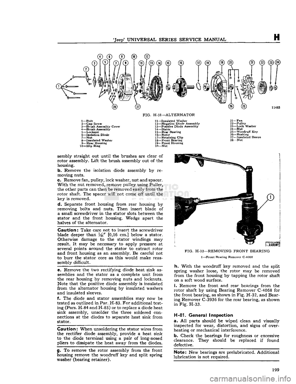
FIG.
H-31—ALTERNATOR
11—
Insulated
Washer 12— Negative Diode Assembly
13—
Positive Diode Assembly
14—
Stator
15—
Rear
Bearing 16—
Rotor
17—
Retaining
Clip
18—
Front
Bearing
19—
Front
Housing
20— Nut 11485
21—
Fan
22—
Pulley
23—
Lock
Washer
24— Nut 25—
Woodruff
Key 26—
Bushing
27—
Insulated
Sleeve
28— Nut sembly straight out until the brushes are clear of
rotor
assembly.
Lift
the brush assembly out of the housing.
b.
Remove the isolation
diode
assembly by re
moving nuts.
c.
Remove fan, pulley, lock
washer,
nut and spacer.
With
the nut removed, remove pulley using
Puller,
the other parts can then be removed easily from the
rotor
shaft. The spacer
will
not
come
off until the key is removed.
d.
Separate front housing from
rear
housing by
removing
bolts
and nuts.
Then
insert blade of
a
small screwdriver in the stator
slots
between
the
stator and the front housing. Wedge apart the
halves of the alternator.
Caution:
Take
care not to insert the screwdriver
blade deeper than J/f6" [0,16 cm.] below a stator.
Otherwise
damage to the stator windings may
result.
It may be necessary to apply pressure at
several
points around the stator to extract rotor
and
front housing as an assembly. Be careful not
to
burr
the stator core as this would make reas sembly difficult.
e.
Remove the two rectifying
diode
heat sink assemblies and the stator as a complete unit from
the
rear
housing by removing nuts and locknuts.
Note
that the positive
diode
assembly is insulated
from
the alternator housing by insulated washers
and
insulated sleeves.
f. The
diode
and stator assemblies may now be
tested
as outlined in
Par.
H-83.
For
additional
test
ing
(Pars.
H-84 and H-85) or to replace a
diode
heat
sink
assembly, unsolder the three soldered con
nections at the
diodes
to separate heat sink from stator.
Caution:
When unsoldering the stator wires from
the rectifier
diode
assembly, provide a heat sink
to the
diode
terminal using a
pair
of long-nosed
pliers
to dissipate the heat away from the diodes.
g.
To remove the rotor assembly from the front
housing remove the woodruff key and split spring
washer
(bearing retainer).
FIG.
H-32—REMOVING
FRONT
BEARING
1—Front
Bearing Remover C-4068
h.
With
the woodruff key removed and the split
spring
washer
loose,
the rotor may be removed
from
the front housing by tapping the rotor shaft
on a
soft
wood surface.
i.
Remove the front and
rear
bearings from the
rotor
shaft by using Bearing Remover C-4068 for
the front bearing, as shown in
Fig.
H-32, and
Bear
ing Remover C-3936 for the
rear
bearing, as shown
in Fig.
H-33.
H-81.
General
Inspection
a.
All parts should be wiped clean and visually inspected for wear, distortion, and signs of over
heating or mechanical interference.
b.
Check
the bearings for roughness or excessive
clearance.
They should be replaced if found defective.
Note:
New bearings are prelubricated. Additional
lubrication
is not required. 199
Page 201 of 376
'Jeep*
UNIVERSAL
SERIES
SERVICE
MANUAL
H
Resistance
should be approximately 0.1 ohm.
An
extremely accurate instrument would be neces
sary
to ascertain shorted turns.
Only
an open condi
tion can be detected with a commercial ohmmeter.
If
the alternator has been disassembled because of
an
electrical malfunction, replace stator only after
all
components have been checked and found to
be satisfactory.
H-85.
Out-Of-Circuit
Rectifier Diode Test
With
the rectifier diode heat sinks disconnected
from
the stator assembly (Par. H-80), the diodes
can
be individually checked with the Diode Tester
C-3829.
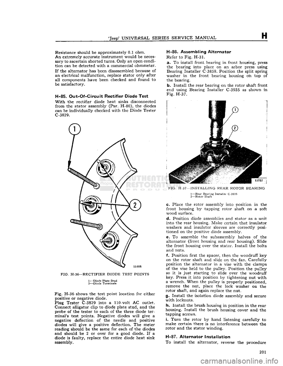
FIG.
H-36—RECTIFIER
DIODE
TEST
POINTS
1— Diode Plate Stud
2—
Diode Terminals
Fig.
H-36 shows the
test
point location for either positive or negative diode.
Plug
Tester C-3829 into a 110-volt AC outlet.
Connect
alligator clip to diode plate stud, and the probe of the tester to each of the three diode ter
minal's
test
points. Negative diodes
will
give a
negative deflection of the needle and positive
diodes
will
give a positive deflection. The meter
reading
should be the same for each of the diodes
and
should be 2 or over for a
good
diode. If a diode is faulty, replace the entire diode heat sink
assembly. H-86.
Assembling Alternator
Refer
to Fig. H-31.
a.
To install front bearing in front housing, press
the bearing into place on an arbor press using
Bearing
Installer C-3858. Position the split spring
washer
in the front bearing housing oh top of the bearing.
b.
Install
the
rear
bearing on the rotor shaft front
end using Bearing Installer C-3935 as shown in
Fig.
H-37.
FIG.
H-37—INSTALLING
REAR
ROTOR
BEARING
1—
Rear
Bearing Installer C-3935
2—
Rotor
Shaft
C.
Place the rotor assembly
into
position in the
front housing by tapping rotor shaft on a
soft
wood surface.
d.
Position diode assemblies and stator as a unit
into the
rear
housing. Make certain that insulator
washers and insulator
sleeves
are correctly posi
tioned on the positive diode assembly.
e.
To assemble the subassembly halves of the
alternator
(front
housing and
rear
housing). Slide
the front housing over the stator.
Install
the bolts
and
nuts.
f. Position first the spacer, then the woodruff key
on the rotor shaft and slide on the fan.
Carefully
position the alternator in a vise with the clamps
of the vise held to the pulley. Position the pulley
so it is just starting to slide over the woodruff
key.
Press it into position by tightening nut with
a
wrench. When the pulley is properly positioned,
remove the nut, place the lock washer on the
rotor
shaft, and again replace the nut.
g.
Install
the isolation diode assembly and secure
with
locknuts.
h.
Install
the brush housing in position in the
rear
housing.
Install
the brush housing cover and the
tapping screws.
i.
Turn
the rotor by hand listening carefully to
make
certain there is no interference between the
rotor
and the stator winding.
H-87.
Alternator Installation
To
install the alternator, reverse the procedure 201
Page 202 of 376
H
ELECTRICAL
SYSTEM
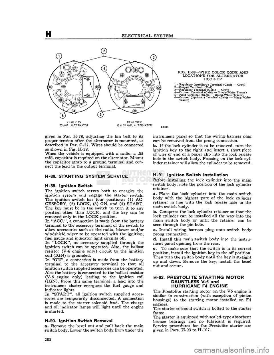
FIG.
H-38—WIRE
COLOR CODE
AND
LOCATIONS
FOR
ALTERNATOR HOOK-UP
1— Regulator (Auxiliary)
Terminal
(Cable —
Grey)
2— Output
Terminal:
(Red)
3—
Regulator
Terminal
(Cable —
Grey)
4—
Ground
Terminal
(Cable — Black-White
Tracer)
5—
Field
Terminal
(Cable — Green-White
Tracer)
6—
Ground
(Optional)
Terminal
(Cable — Black-White
Tracer)
REAR
VIEW
35
AMP.
ALTERNATOR
REAR
VIEW
40
& 55 AMP.
ALTERNATOR
given in Par. H-78, adjusting the fan belt to its
proper tension after the alternator is mounted, as described in Par. C-27. Wires should be connected
as shown in Fig. H-38.
When
the vehicle is equipped with a radio, a .55
mfd. capacitor is required on the alternator. Mount
the capacitor strap to a ground terminal and con
nect the lead to the output terminal.
H-88.
STARTING
SYSTEM
SERVICE
H-89.
Ignition
Switch
The
ignition switch serves both to energize the
ignition system and
engage
the starter switch.
The
ignition switch has four positions: (1) AC
CESSORY,
(2)
LOCK,
(3) ON, and (4)
START. The
key must be in the switch to turn it to any position other than
LOCK,
and the key can be
removed only in the
LOCK
position.
In "ACC",
a connection is made from the battery
terminal
to the accessory terminal of the switch to
allow accessories such as the radio, blower and/or
windshield wiper to be operated with the ignition, fuel
gauge
and indicator light circuits off.
In "LOCK",
no accessory supplied through the
ignition switch can be operated. Also, the ballast
resistor (V-6
engine
only) circuit to the ignition
coil
(IGN) is grounded.
In
"ON", a connection is made from the battery
terminal
to the accessory terminal so that all
ignition switch supplied accessories can be operated. Also the battery is connected to the ballast resistor
(V-6
engine
only) leading to the ignition coil
(IGN).
From
this same terminal, a lead
into
the
instrument cluster energizes the fuel
gauge
and
indicator lights.
In "START",
all ignition switch supplied acces
sories are temporarily disconnected. A connection is made to the starter solenoid lead. The charge
and
oil indicator lamps
will
light until the
engine
is started.
H-90.
Ignition
Switch
Removal
a.
Remove the bezel nut and pull back the main
switch body.
Lower
the switch
body
from under the instrument panel so that the wiring harness plug
can
be removed from the prong connection,
b. If the lock cylinder is to be removed, turn the
ignition key to the right and insert a short
piece
of wire or end of a paper clip
into
the lock release
hole
in the switch body. Pressing on the lock
cyl
inder retainer
will
allow the cylinder to be removed.
H-91.
Ignition
Switch
Installation
Before installing the lock cylinder
into
the main
switch body,
note
the position of the lock cylinder
retainer.
a.
Place the lock cylinder
into
the main switch
body
with the highest part of the lock cylinder
retainer in line with the lock release
hole
in the
main
switch body.
b. Compress the lock cylinder retainer so that the
lock cylinder can be installed all the way
into
the
main
switch
body
or until the retainer can be
seen
through the pin hole.
c.
Install
wiring harness plug
onto
switch
body
prong connection.
d.
Install
this main switch
body
into
the instru
ment panel opening from the
rear.
e. To make sure that the switch is in its correct position, install the ignition key in the off position.
Then
turn the switch
body
until the key is straight
up and down. Remove the key, install the bezel
nut and secure.
H-92.
PRESTOLITE
STARTING
MOTOR
DAUNTLESS
V-6 and
HURRICANE
F4
ENGINE
The
Prestolite starting motor on the V6
engine
is
similar
in construction (with exception of pinion housings) to the starting motor installed on F4
engines.
The
starter solenoid switch is bolted to the starter
frame.
The
starter is equipped with
sealed-type
absorbent
bronze bearings and no lubricant is required. Service procedures for the Prestolite starter are
given in
Pars.
H-93 to H-107. 202
Page 204 of 376
H
ELECTRICAL
SYSTEM
11035
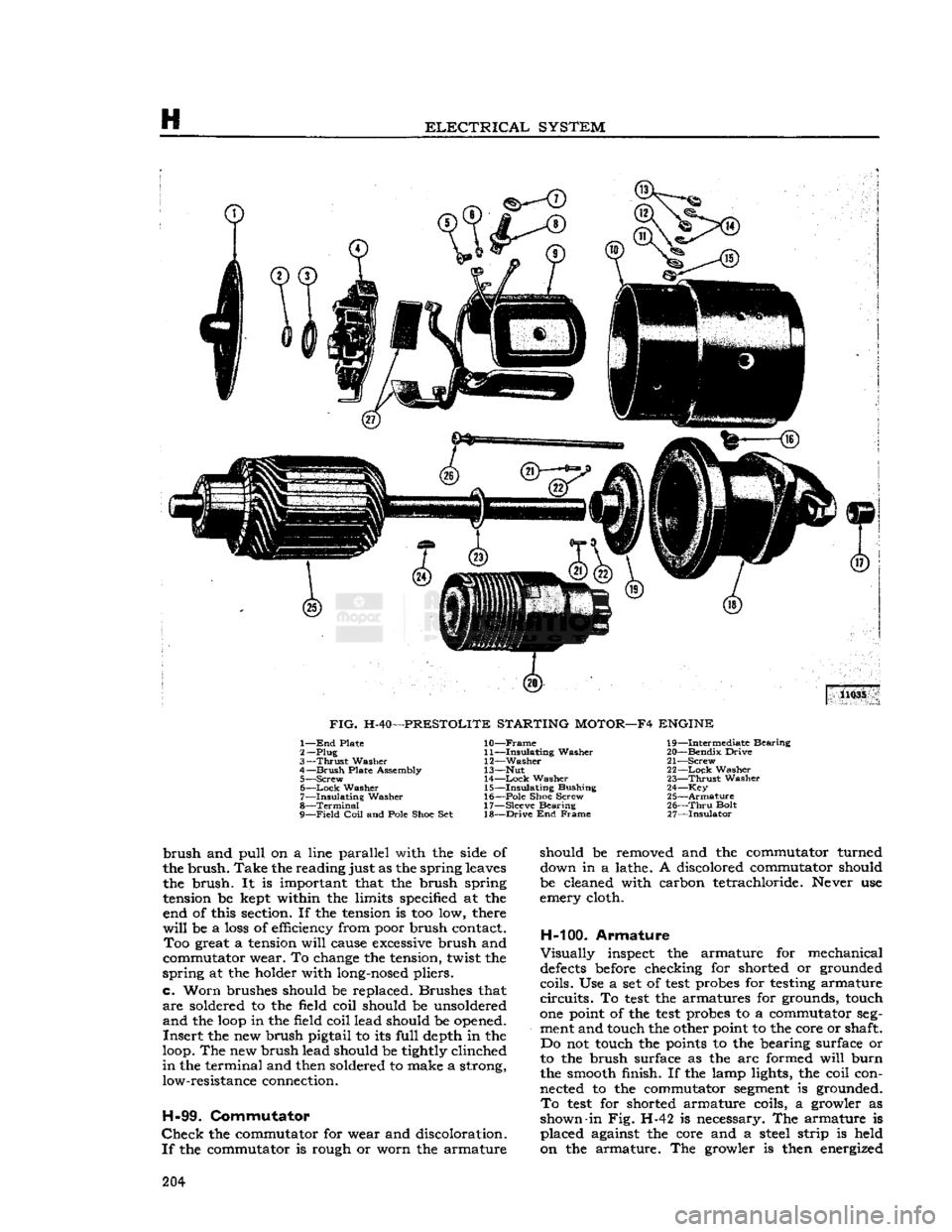
FIG.
H-40—PRESTOLITE STARTING MOTOR—F4 ENGINE 1— End
Plate
2—
Plug
3—
Thrust
Washer
4—
Brush
Plate Assembly 5— Screw
6—
—Lock
Washer
7—
Insulating
Washer
8—
Terminal
9—
Field
Coil
and Pole
Shoe
Set
10—
Frame
11—
Insulating
Washer
12—
Washer
13— Nut 14—
Lock
Washer
15—
Insulating
Bushing
16—
Pole
Shoe
Screw
17— Sleeve Bearing
18—
Drive
End Frame
19—
Intermediate Bearing
20—
Bendix
Drive
21—
Screw
22—
Lock
Washer
23—
Thrust
Washer
24— Key
25—
Armature
26—
Thru
Bolt
27—
Insulator
brush
and
pull
On
a line parallel with the side of
the
brush.
Take
the
reading
just as the spring leaves the
brush.
It is important that the brush spring
tension be kept within the limits specified at the end of this section. If the tension is too low, there
will
be a loss of efficiency from poor brush contact.
Too
great a tension
will
cause excessive brush and
commutator wear. To change the tension, twist the
spring
at the holder with long-nosed pliers,
c.
Worn
brushes should be replaced. Brushes that
are
soldered to the field coil should be unsoldered
and
the
loop
in the field coil lead should be opened.
Insert
the new brush pigtail to its
full
depth in the
loop. The new brush lead should be tightly clinched
in
the terminal and then soldered to make a strong, low-resistance connection.
H-99.
Commutator
Check
the commutator for wear and discoloration.
If
the commutator is rough or worn the armature should be removed and the commutator turned
down in a lathe. A discolored commutator should
be cleaned with carbon tetrachloride. Never use
emery cloth.
H-100.
Armature
Visually
inspect the armature for mechanical
defects
before checking for shorted or grounded
coils. Use a set of
test
probes for testing armature
circuits.
To
test
the armatures for grounds, touch
one point of the
test
probes to a commutator seg
ment and touch the other point to the core or shaft. Do not touch the points to the bearing surface or
to the brush surface as the arc formed
will
burn
the smooth finish. If the lamp lights, the coil con nected to the commutator segment is grounded.
To
test
for shorted armature coils, a growler as
shown-in Fig. H-42 is necessary. The armature is placed against the core and a steel strip is held
on the armature. The growler is then energized 204
Page 207 of 376
'Jeep'
UNIVERSAL
SERIES
SERVICE
MANUAL
H
require
a slight rotation of the pinion to index it
into the ring gear. When the
engine
starts the drive
pinion
will
automatically demesh from the ring
gear and return to its normal position.
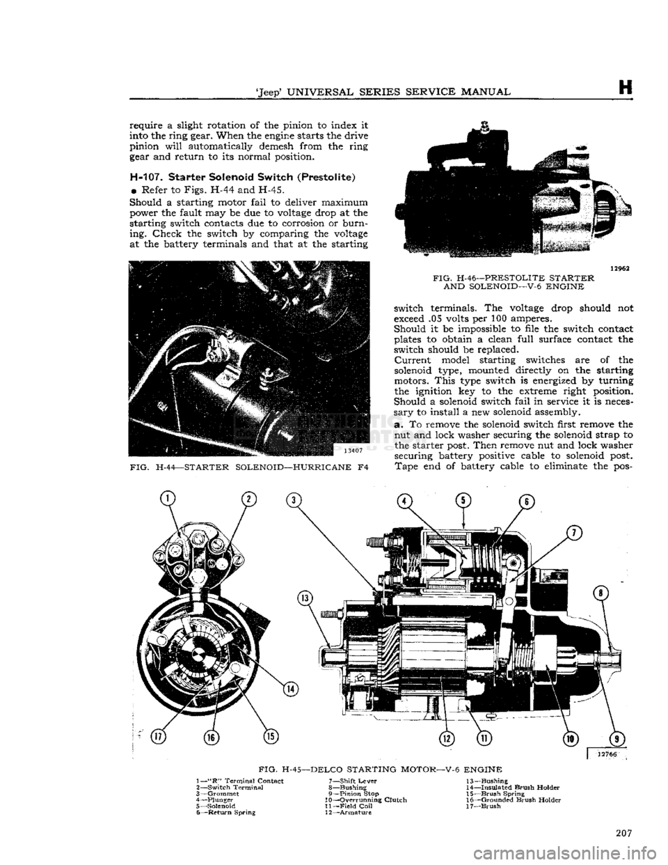
H-107. Starter Solenoid Switch (Prestolite)
•
Refer to
Figs.
H-44 and H-45.
Should
a starting motor
fail
to deliver maximum power the fault may be due to
voltage
drop at the
starting switch contacts due to corrosion or
burn
ing.
Check
the switch by comparing the
voltage
at the battery terminals and that at the starting 13407
FIG.
H-44—STARTER SOLENOID—HURRICANE
F4
FIG.
H-46—PRESTOLITE STARTER
AND SOLENOID—V-6 ENGINE
switch terminals. The
voltage
drop should not
exceed .05 volts per 100 amperes.
Should
it be impossible to file the switch contact
plates to obtain a clean
full
surface contact the
switch should be replaced.
Current
model starting switches are of the
solenoid type, mounted directly on the starting
motors.
This
type switch is energized by turning
the ignition key to the extreme right position.
Should
a solenoid switch
fail
in service it is neces
sary
to install a new solenoid assembly,
a.
To remove the solenoid switch first remove the nut and lock washer securing the solenoid strap to the starter
post.
Then
remove nut and lock washer securing battery positive cable to solenoid
post.
Tape
end of battery cable to eliminate the pos- 207
Page 211 of 376
'Jeep'
UNIVERSAL
SERIES SERVICE
MANUAL
H
Note:
Pinion clearance cannot be adjusted. If
clearance is not correct, motor must be disassem
bled and checked for the above mentioned defects.
Any
defective parts must be replaced.
H-118. Starting Motor Test —
Genera!
To
obtain
full
performance data on a starting motor, or to determine the cause of abnormal
operation, the motor should be submitted to no-
load and locked armature
tests,
with equipment designed for such
tests.
A high-current variable resistance is required to obtain the specified volt
age at the starting motor.
This
is necessary since
a
small variation in the
voltage
will
produce a
marked
difference in the current
drawn.
H-119.
Starting Motor No-Load Test
This
test
requires a DC voltmeter capable of
read
ing
voltages
in a 12-volt
circuit,
a DC ammeter
with
maximum range of several hundred amperes,
a
high-current variable resistance, an rpm. in
dicator,
and a fully-charged, 12-volt battery.
a.
Connect a jumper lead
between
S terminal
and
large battery terminal of starter solenoid.
Con
nect voltmeter
between
either of
these
terminals (positive) and motor frame (negative, ground).
Connect
ammeter and variable resistance in series
between
positive terminal of battery and battery
terminal
of solenoid. Set up rpm. indicator to show starting motor speed.
b.
Initially,
adjust variable resistance to a value of
approximately .25 ohm. To complete the
circuit,
connect negative terminal of battery to motor
frame.
Adjust variable resistance to obtain a volt meter reading of 10.6 volts;
note
speed of starting motor and ammeter reading. Motor speed should
be
6750
to
10,500
rpm.; ammeter reading should
be 50 to 80 amperes.
c. Rated speed and current indicate normal condi
tion of the starting motor. Low speed and high
cur
rent
may show friction; this could be caused by
tight, dirty, or worn bearings, bent armature shaft,
or
a
loose
field
pole
shoe
dragging against the
armature.
It could also be caused by a short-cir cuited armature, or by grounded armature or field
coils.
d.
Failure
to operate and high current indicates
a
direct short circuit to ground at either the battery
terminal
or field coils.
e.
Failure
to operate and no current are usually
caused by broken brush springs, worn brushes, high insulation
between
commutator
bars,
or
some
other
condition preventing
good
contact
between
the brushes and commutator. It can also be caused by
open circuit in either the field coils or armature coils.
f. Low speed and low current show high resistance due to poor connections, defective leads, dirty com
mutator, or one of the conditions mentioned in e,
above.
g. High speed and high current indicates a short
circuit
in the field coils. H-120-
Locked
Armature Test
This
test
requires a DC voltmeter with range ap
propriate
to read
voltages
in a 12-volt
circuit,
a DC
ammeter with maximum range of several hundred
amperes, a high-current variable resistance, a
clamping fixture to lock
together
the motor shaft
and
case, and a fully-charged 12-volt battery.
a.
Connect a jumper lead
between
S terminal and
large battery terminal of starter solenoid. Connect
voltmeter
between
either of
these
terminals (posi
tive) and motor frame (negative, ground). Connect
ammeter and variable resistance in series
between
positive terminal of battery and battery terminal
of solenoid.
Install
clamping fixture to lock motor
shaft and case
together
securely.
b.
Initially,
adjust variable resistance to approxi
mately .05 ohm. To complete the
circuit,
connect
negative terminal of battery to motor frame. Ad
just
variable resistance to obtain a voltmeter
read
ing of 4.0 volts. Ammeter reading should be 280
to 320 amperes.
H-121.
Solenoid Starter Switch — Delco
The
solenoid-type switch is mounted directly on
the starting motor.
This
type of switch is energized
by turning the ignition key to the extreme right position. Should the solenoid switch
fail
in service
it
is necessary to install a new assembly.
Should
a starting motor
fail
to deliver maximum power the fault may be due to
voltage
drop at the
starter
switch contacts due to corrosion or burning.
Check
the switch by comparing the
voltage
at the
battery across the terminals. The
voltage
drop
should not exceed .05 volts per 100 amperes.
In
order to remove the starter solenoid, it is neces
sary
to remove the starter assembly.
H-122.
ELECTRICAL
INSTRUMENTS
H-123.
Fuel
Gauge —
CJ-3B
The
fuel
gauge
circuit is composed of the indicating
unit,
mounted on the instrument panel, and the
fuel tank unit, connected by a single wire through the ignition switch.
Should
the
gauge
fail
to register, check all wire con nections to be sure they are tight and clean; also
be sure both units are well grounded. If, after this
check, the
gauge
does
not indicate properly, remove
the wire from the tank unit and connect it to a
new tank unit which must be grounded to the tank
or
frame for
test.
Turn
the ignition switch "ON"
and
move
the float arm through its range of travel,
watching the dash unit to determine if it indicates
correctly.
If it fails to do so the trouble is probably
in
the dash unit and it should be replaced.
Should
a new tank unit be unavailable for this
test,
disconnect tank unit wire at the instrument panel
gauge.
Connect one lead of a 12 V, 1 CP
test
light
to the instrument panel unit terminal and with the
ignition switch
"ON"
ground the other lead. If the
unit is operating correctly the pointer
will
move
approximately three-quarter across the
dial.
Do not attempt to repair either unit; replacement
is the only precedure. 211
Page 225 of 376
'Jeep'
UNIVERSAL
SERIES SERVICE
MANUAL
CLUTCH
Contents
SUBJECT
PAR.
GENERAL
.1-1
Clutch
Maintenance 1-2
Clutch
Pedal Linkage and Adjustment.... 1-3
Pilot Bushing Inspection and
Replacement 1-8
CLUTCH
—HURRICANE
F4
ENGINE.
. . .1-4
Clutch
Removal. 1-5
Clutch
Pressure Plate and Disc Inspection.
.
1-6
Clutch
Pressure Plate Adjustment 1-7
Clutch
Installation 1-9
CLUTCH
—DAUNTLESS
V-6
ENGINE,
DIAPHRAGM
SPRING
TYPE
1-10
Clutch
Removal.
........
.1-11
Clutch
Inspection, Diaphragm Spring Type. . 1-12
Clutch
Installation 1-27
SUBJECT
PAR.
SERVICING COIL
SPRING
TYPE CLUTCH
. .1-13 Pressure Plate Adjustment. 1-14
Pressure Plate Disassembly. . . . . 1-15
Inspection of Parts 1-16 thru 1-20 Pressure Plate Reassembly. . . . .1-21 thru 1-23
Clutch
Lever Adjustment 1-24
Clutch
Fitxure . .1-26
CLUTCH
THROWOUT
RELEASE
BEARING
1-25
SERVICE
DIAGNOSIS
1-28
CLUTCH
SPECIFICATIONS
1-29
CLUTCH
ADJUSTING
FIXTURE
DATA
1-30
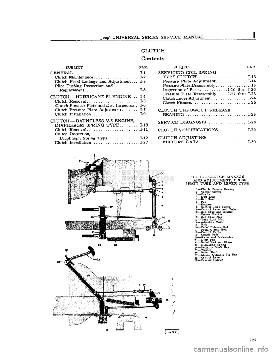
FIG.
I-1—CLUTCH
LINKAGE AND
ADJUSTMENT,
CROSS
SHAFT
TUBE
AND
LEVER
TYPE
1—
Clutch
Release Bearing
2—
Carrier
Spring
3—
Bracket
4— Dust Seal 5—
Ball
Stud 6—
Pad
7— Retainer
8—
Control
Tube Spring
9—
Control
Lever and Tube
10—
Ball
Stud and Bracket
11—
Frame
Bracket
12—
Ball
Stud Nut 13—
Yoke
Lock
Nut
14— Adjusting Yoke
15— Bolt
16— Pedal Release Rod
17— Pedal Clamp Bolt 18—
Control
Cable
19—
Clutch
Pedal
20— Screw and Lockwasher
21—
Draft
Pad 22— Pedal Pad and Shank
23— Retracting Spring
24— Pedal to Shaft Key 25— Washer
26— Pedal Shaft
27— Master Cylinder Tie Bar
28—
Control
Lever
29— Bearing
Carrier
10734
225