light JEEP CJ 1953 Manual PDF
[x] Cancel search | Manufacturer: JEEP, Model Year: 1953, Model line: CJ, Model: JEEP CJ 1953Pages: 376, PDF Size: 19.96 MB
Page 182 of 376
H
ELECTRICAL
SYSTEM
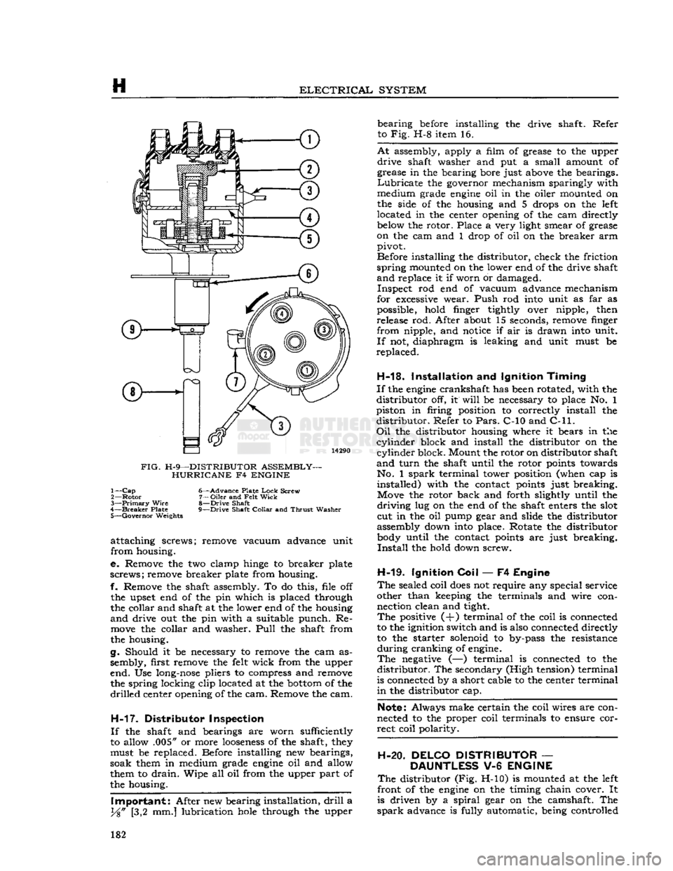
FIG.
H-9—DISTRIBUTOR ASSEMBLY- HURRICANE F4 ENGINE 1—
Cap
6—Advance Plate
Lock
Screw
2—
Rotor
7—Oiler and
Felt
Wick
3—
Primary
Wire
8—Drive Shaft
4—
Breaker
Plate 9—Drive Shaft
Collar
and
Thrust
Washer 5—
Governor
Weights
attaching screws; remove vacuum advance unit
from housing.
e. Remove the two clamp
hinge
to breaker plate
screws; remove breaker plate from housing.
f. Remove the shaft assembly. To do this, file off
the upset end of the pin which is placed through
the collar and shaft at the lower end of the housing
and
drive out the pin with a suitable punch. Re
move
the collar and washer.
Pull
the shaft from
the housing.
g. Should it be necessary to remove the cam as
sembly, first remove the
felt
wick from the upper
end. Use
long-nose
pliers to compress and remove the spring locking clip located at the
bottom
of the
drilled
center opening of the cam. Remove the cam.
H-17.
Distributor Inspection
If
the shaft and bearings are worn sufficiently
to allow .005" or more
looseness
of the shaft,
they
must be replaced. Before installing new bearings,
soak them in medium grade
engine
oil and allow
them to
drain.
Wipe all oil from the upper part of
the housing.
Important:
After new bearing installation,
drill
a
y%"
[3,2 mm.] lubrication
hole
through the upper bearing
before
installing the drive shaft. Refer
to Fig. H-8 item 16.
At
assembly, apply a film of grease to the upper
drive
shaft washer and put a small amount of
grease in the bearing bore just
above
the bearings.
Lubricate
the governor mechanism sparingly with
medium grade
engine
oil in the oiler mounted on
the side of the housing and 5 drops on the
left
located in the center opening of the cam directly
below
the rotor. Place a very light smear of grease
on the cam and 1 drop of oil on the breaker arm pivot.
Before installing the distributor, check the friction
spring
mounted on the lower end of the drive shaft
and
replace it if worn or damaged. Inspect rod end of vacuum advance mechanism
for
excessive
wear. Push rod
into
unit as far as
possible, hold finger tightly over nipple, then release rod. After about 15 seconds, remove finger
from nipple, and
notice
if air is drawn
into
unit.
If
not, diaphragm is leaking and unit must be
replaced.
H-18.
Installation and Ignition
Timing
If
the
engine
crankshaft has
been
rotated, with the
distributor off, it
will
be necessary to place No. 1
piston in firing position to correctly install the distributor. Refer to
Pars.
C-10 and
C-ll. Oil
the distributor housing where it bears in the
cylinder
block and install the distributor on the
cylinder
block. Mount the rotor on distributor shaft
and
turn
the shaft until the rotor
points
towards No. 1
spark
terminal tower position (when cap is installed) with the contact
points
just breaking. Move the rotor back and forth slightly until the
driving
lug on the end of the shaft enters the
slot
cut in the oil pump gear and slide the distributor
assembly down
into
place. Rotate the distributor
body
until the contact
points
are just breaking.
Install
the hold down screw.
H-19.
Ignition
Coil
— F4 Engine
The
sealed coil
does
not require any special service
other than keeping the terminals and wire con nection clean and tight.
The
positive (+) terminal of the coil is connected
to the ignition switch and is also connected directly
to the starter solenoid to by-pass the resistance
during
cranking of
engine.
The
negative
(—) terminal is connected to the
distributor. The secondary (High tension) terminal
is connected by a short cable to the center terminal
in
the distributor cap.
Note:
Always make certain the coil wires are con
nected to the proper coil terminals to ensure cor
rect coil polarity.
H-20. DELCO DISTRIBUTOR
—
DAUNTLESS
V-6
ENGINE
The
distributor (Fig. H-10) is mounted at the
left
front of the
engine
on the timing chain cover. It
is driven by a
spiral
gear on the camshaft. The
spark
advance is fully automatic, being controlled 182
Page 186 of 376
ELECTRICALJ
SYSTEM
d.
Inspect for
excessive
wear
between
centrifugal
weights
and advance cam and pivot pins.
Turn
weight
base plate in a clockwise direction until
weights
are fully extended. Release and allow
springs to return
weights
to
retard
position. Repeat several times. Springs should return
weights
to
stop
without sticking and there should be no
excessive
free
movement
in the
retard
position. Inspect
springs for distortion and fatigue.
e. Inspect cam
lobes
for scoring or
excessive
wear.
Check
weight
base plate for binding or
excessive
looseness
on distributor shaft.
f.
Check
breaker plate for
excessive
looseness
on
outside
diameter of upper distributor shaft bushing.
Check
breaker plate ground lead for poor
spot
we
Id
at plate end and for
loose
or frayed terminal con
nections.
g.
Check
for
excessive
wear
between
distributor
shaft and bushings in housing. Inspect shaft for distortion. Inspect gear for scoring of
teeth
or
excessive
wear.
h.
Inspect rod end of vacuum advance mechanism
for
excessive
wear. Push rod
into
unit as far as
possible, hold finger tightly over nipple, then re
lease
rod. After about 15 seconds, remove finger
from nipple, and
notice
if air is drawn
into
unit.
If
not, diaphragm is leaking and unit must be
replaced.
H-29.
Distributor Reassembly
Refer
to Fig. H-l5.
a.
Install
distributor
primary
lead and rubber grommet in distributor housing. Mount vacuum
advance unit on housing with two
slotted
attaching
screws; insert ground lead terminal of breaker plate under outer mounting screw.
b.
Install
felt
washer over upper shaft bushing of
distributor housing and apply a few drops of light
oil.
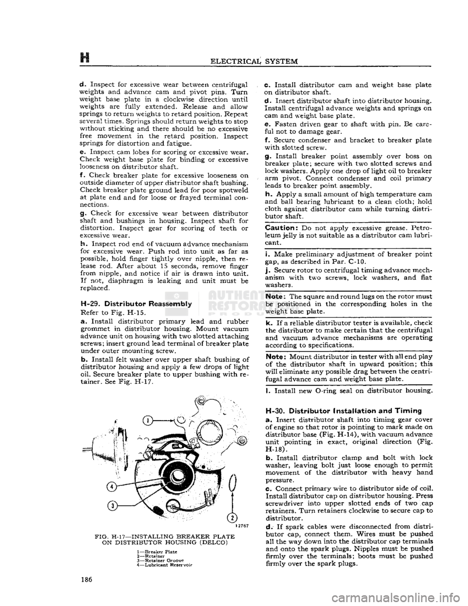
Secure breaker plate to upper bushing with re tainer. See Fig. H-17.
12767
FIG.
H-17—INSTALLING
BREAKER
PLATE
ON
DISTRIBUTOR
HOUSING
(DELCO)
1—
Breaker
Plate
2—
Retainer
3—
Retainer
Groove
4—
Lubricant
Reservoir c.
Install
distributor cam and
weight
base plate
on distributor shaft.
d.
Insert distributor shaft
into
distributor housing.
Install
centrifugal advance
weights
and springs on
cam
and
weight
base plate. e. Fasten driven gear to shaft with pin. Be care
ful
not to damage gear.
f.
Secure condenser and bracket to breaker plate
with
slotted
screw.
g.
Install
breaker point assembly over
boss
on
breaker
plate; secure with two
slotted
screws and
lock washers. Apply one drop of light oil to breaker
arm
pivot. Connect condenser and coil
primary
leads to breaker point assembly.
h.
Apply a small amount of high temperature cam
and
ball
bearing lubricant to a clean cloth; hold cloth against distributor cam while turning
distri
butor shaft.
Caution:
Do not apply
excessive
grease. Petro
leum jelly is not suitable as a distributor cam
lubri
cant.
i.
Make preliminary adjustment of breaker point
gap, as described in Par. C-10.
].
Secure rotor to centrifugal timing advance mech
anism with two screws, lock washers, and flat
washers.
Note:
The square and round
lugs
on the rotor must
be positioned in the corresponding
holes
in the
weight
base plate.
k. If a reliable distributor tester is available, check
the distributor to make certain that the centrifugal
and
vacuum advance mechanisms are operating
according to specifications.
Note:
Mount distributor in tester with all end play
of the distributor shaft in upward position; this
will
eliminate any possible drag
between
the centri fugal advance cam and
weight
base plate.
I.
Install
new
O-ring
seal on distributor housing.
H-30.
Distributor
Installation
and
Timing
a.
Insert distributor shaft
into
timing gear cover
of
engine
so that rotor is pointing to
mark
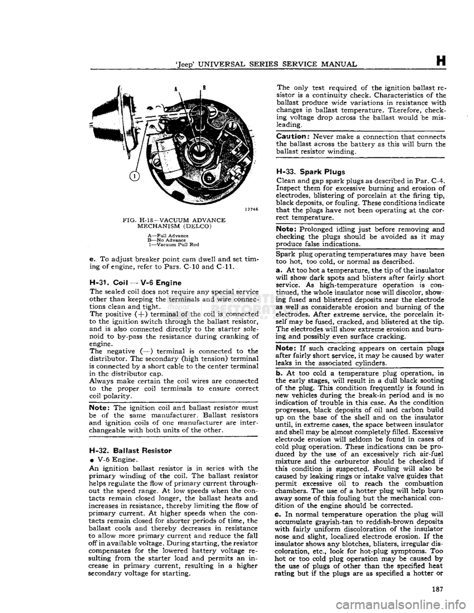
made on distributor base (Fig. H-14), with vacuum advance
unit pointing in exact, original direction (Fig.
H-18).
b.
Install
distributor clamp and
bolt
with lock
washer, leaving
bolt
just
loose
enough
to permit
movement
of the distributor with heavy hand
pressure.
C.
Connect
primary
wire to distributor side of coil.
Install
distributor cap on distributor housing. Press
screwdriver
into
upper
slotted
ends
of two cap
retainers.
Turn
retainers clockwise to secure cap to distributor.
d.
If
spark
cables were disconnected from
distri
butor cap, connect them. Wires must be pushed
all
the way down
into
the distributor cap terminals
and
onto
the
spark
plugs. Nipples must be pushed
firmly
over the terminals;
boots
must be pushed
firmly
over the
spark
plugs. 186
Page 187 of 376
'Jeep'
UNIVERSAL
SERIES SERVICE
MANUAL
H
12746
FIG.
H-l8—VACUUM
ADVANCE
MECHANISM
(DELCO)
A—Full
Advance
B—No
Advance
1—Vacuum
Pull
Rod
e.
To adjust breaker point cam dwell and set tim
ing of engine, refer to
Pars.
C-10 and
C-ll.
H-31. Coil
— V-6 Engine
The
sealed coil
does
not require any special service
other than keeping the terminals and wire connec
tions clean and tight.
The
positive (+) terminal of the coil is connected
to the ignition switch through the ballast resistor,
and
is also connected directly to the starter
sole
noid to by-pass the resistance during cranking of
engine.
The
negative (—) terminal is connected to the
distributor.
The secondary (high tension) terminal
is connected by a short cable to the center terminal
in
the distributor cap.
Always
make certain the coil wires are connected to the proper coil terminals to ensure correct
coil
polarity.
Note:
The ignition coil and ballast resistor must
be of the same manufacturer. Ballast resistors
and
ignition coils of one manufacturer are interchangeable with both units of the other. H-32.
Ballast
Resistor
•
V-6 Engine.
An
ignition ballast resistor is in series with the
primary
winding of the coil. The ballast resistor
helps regulate the flow of
primary
current through
out the speed range. At low
speeds
when the con
tacts remain closed longer, the ballast heats and
increases in resistance, thereby limiting the flow of
primary
current. At higher
speeds
when the con
tacts remain closed for shorter periods of time, the ballast
cools
and thereby decreases in resistance
to allow more
primary
current and reduce the
fall
off
in
available voltage.
During
starting, the resistor compensates for the lowered battery
voltage
re
sulting from the starter load and permits an in crease in
primary
current, resulting in a higher
secondary
voltage
for starting.
The
only
test
required of the ignition ballast re
sistor is a continuity check. Characteristics of the ballast produce wide variations in resistance with
changes in ballast temperature. Therefore, check ing
voltage
drop across the ballast would be mis
leading.
Caution:
Never make a connection that connects
the ballast across the battery as this
will
burn
the ballast resistor winding.
H-33.
Spark
Plugs
Clean
and gap
spark
plugs as described in
Par.
C-4.
Inspect them for excessive burning and erosion of
electrodes, blistering of porcelain at the firing tip,
black
deposits, or fouling. These conditions indicate
that the plugs have not been operating at the cor
rect
temperature.
Note:
Prolonged idling just before removing and
checking the plugs should be avoided as it may
produce false indications.
Spark
plug operating temperatures may have been
too hot, too cold, or normal as described.
a.
At too hot a temperature, the tip of the insulator
will
show
dark
spots
and blisters after fairly short service. As high-temperature operation is con
tinued, the whole insulator
nose
will
discolor, show
ing fused and blistered
deposits
near the electrode
as well as considerable erosion and burning of the
electrodes. After extreme service, the porcelain it self may be fused, cracked, and blistered at the tip.
The
electrodes
will
show extreme erosion and
burn
ing and possibly even surface cracking.
Note:
If such cracking appears on certain plugs
after fairly short service, it may be caused by water
leaks in the associated cylinders.
b. At too cold a temperature plug operation, in
the early
stages,
will
result in a
dull
black
sooting
of the plug.
This
condition frequently is found in new vehicles during the break-in period and is no
indication of trouble in this case. As the condition progresses, black
deposits
of oil and carbon build
up on the base of the shell and on the insulator
until,
in extreme cases, the space
between
insulator
and
shell may be almost completely filled. Excessive
electrode erosion
will
seldom be found in cases of cold plug operation. These indications can be pro
duced by the use of an excessively
rich
air-fuel mixture and the carburetor should be checked if
this condition is suspected. Fouling
will
also be
caused by leaking rings or intake valve
guides
that
permit excessive oil to reach the combustion
chambers.
The use of a hotter plug
will
help
burn
away
some
of this fouling but the mechanical con dition of the
engine
should be corrected.
c. In normal temperature operation the plug
will
accumulate grayish-tan to reddish-brown
deposits
with
fairly uniform discoloration of the insulator
nose
and slight, localized electrode erosion. If the
insulator shows any blotches, blisters,
irregular
dis
coloration, etc., look for hot-plug symptoms. Too
hot or too cold plug operation may be caused by
the use of plugs of other than the specified heat
rating
but if the plugs are as specified a hotter or 187
Page 188 of 376
H
ELECTRICAL
SYSTEM
colder plug may be desirable. However, under- or
over-heating is usually caused by factors other than the type of
spark
plugs and the cause should be determined before changing plugs. The design of the
engine
calls for plugs equivalent to Champion
J-8
for F4
engines
and
A.C.
44S or
UJ12Y
Champ
ion for the V6 engines, (as installed in production)
though any factor that consistently affects
engine
operating temperature may cause this requirement
to change. Overheating may be caused by in sufficient tightening of the plug in the head, which interferes with the flow of heat away from the firing
tip.
If this is the case, the plug gasket
will
show very
little flattening. Over-tightening, in
turn,
will
pro duce too easy a heat flow path and result in cold
plug operation.
This
will
be evident by excessive
flattening
and
deformation of the gasket.
Prevailing
temperatures, condition of the cooling system, and
air-fuel
mixture can affect the
engine
operating temperature and should be taken into consideration.
H-34.
GENERATOR
— F4
ENGINE
The
generator is an air-cooled, two-brush unit
which
cannot be adjusted to increase or decrease output. For replacement,
voltage
regulator and generator must be matched for
voltage
and capa
city,
polarity, and common source of manufacture.
Otherwise,
either a
loss
of ampere capacity or a
burned
out generator
will
result. Generators for
these
vehicles are 12-volt. Par. H-l explains the 12-volt system. Refer to the specifications at the
end of this section for information on correct generator rating for a specific model series.
The
circuit
breaker,
voltage
regulator, and current-
limiting
regulator are built into one combination
unit.
Because the regulator and battery are part
of the generator
circuit,
the output of the generator
depends upon the
state
of charge and temperature
of the battery.
With
a discharged battery, the
output
will
be high, decreasing proportionally as the battery
becomes
charged. For service informa
tion covering current regulator see Par. H-41.
H-36.
Generator
Maintenance
A
periodic inspection should be made of the charg
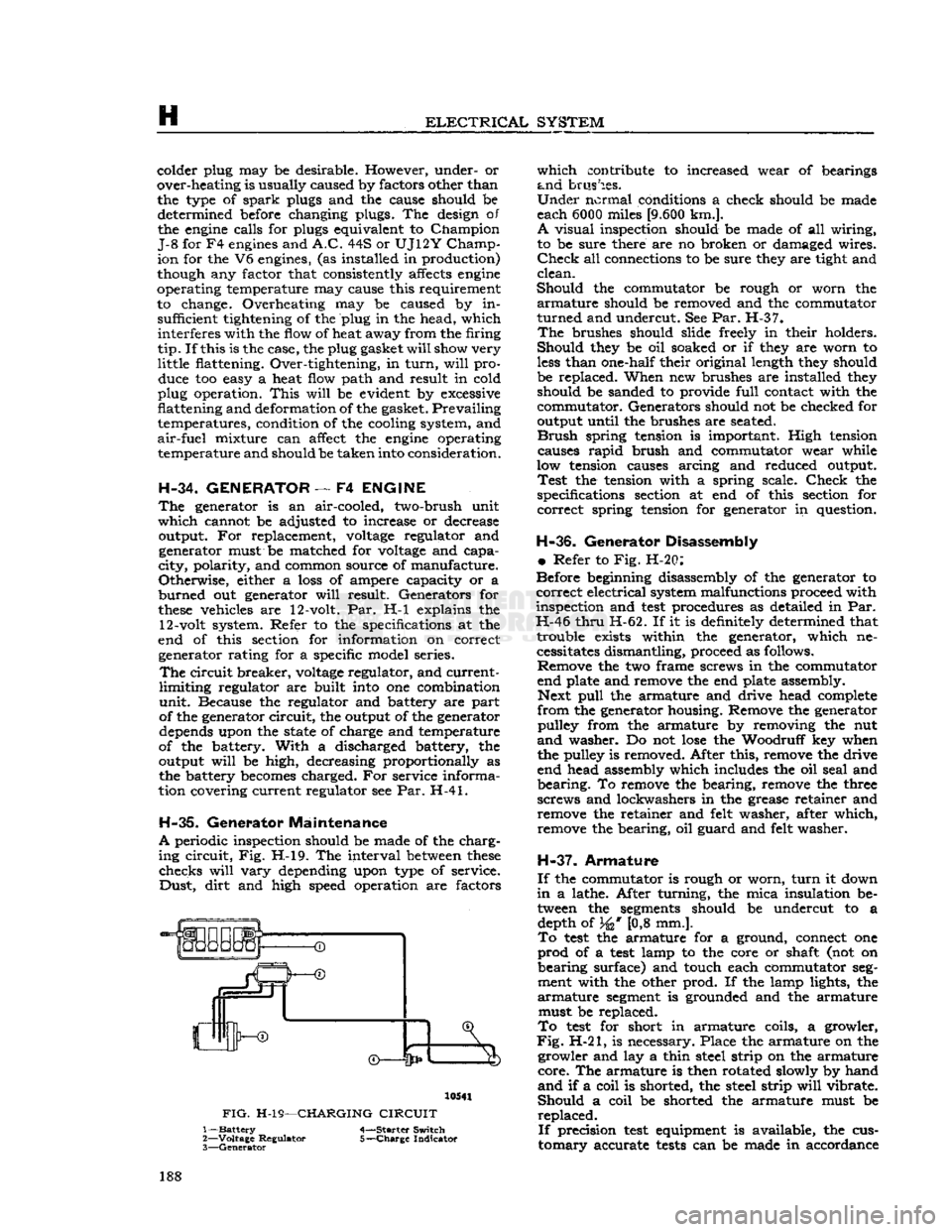
ing
circuit,
Fig. H-l9. The interval
between
these
checks
will
vary
depending upon type of service.
Dust,
dirt
and high speed operation are factors 10541
FIG.
H-19—CHARGING
CIRCUIT
1—
Battery
4-—Starter Switch
2—
Voltage
Regulator 5-—Charge Indicator
3—
Generator
which
contribute to increased wear of bearings
and
brushes.
Under
normal conditions a check should be made
each 6000 miles
[9.600
km.].
A
visual inspection should be made of all wiring,
to be sure there are no broken or damaged wires.
Check
all connections to be sure they are tight and
clean.
Should
the commutator be rough or worn the
armature
should be removed and the commutator
turned
and undercut. See Par. H-37.
The
brushes should slide freely in their holders.
Should
they be oil soaked or if they are worn to
less
than one-half their original length they should
be replaced. When new brushes are installed they should be sanded to provide
full
contact with the
commutator. Generators should not be checked for
output until the brushes are seated.
Brush
spring tension is important. High tension causes
rapid
brush and commutator wear while
low tension causes arcing and reduced output.
Test
the tension with a spring scale.
Check
the
specifications section at end of this section for
correct
spring tension for generator in question.
H-36.
Generator Disassembly
•
Refer to Fig. H-20:
Before beginning disassembly of the generator to
correct
electrical system malfunctions proceed with
inspection and
test
procedures as detailed in Par.
H-46
thru
H-62. If it is definitely determined that trouble exists within the generator, which necessitates dismantling, proceed as follows. Remove the two frame screws in the commutator
end plate and remove the end plate assembly. Next
pull
the armature and drive head complete
from
the generator housing. Remove the generator pulley from the armature by removing the nut
and
washer. Do not
lose
the Woodruff key when
the pulley is removed. After this, remove the drive
end head assembly which includes the oil seal and
bearing.
To remove the bearing, remove the three
screws and lockwashers in the grease retainer and remove the retainer and felt washer, after which,
remove the bearing, oil guard and felt washer.
H-37.
Armature
If
the commutator is rough or worn,
turn
it down
in
a lathe. After turning, the mica insulation be tween the
segments
should be undercut to a depth of 34* [0,8 mm.].
To
test
the armature for a ground, connect one
prod
of a
test
lamp to the core or shaft (not on
bearing
surface) and touch each commutator
seg
ment with the other prod. If the lamp lights, the
armature
segment
is grounded and the armature must be replaced.
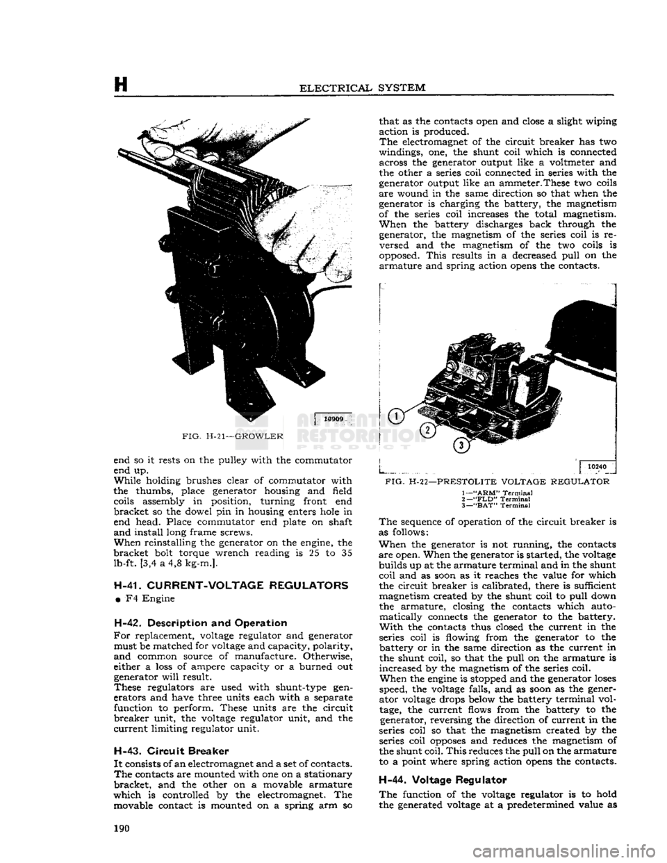
To
test
for short in armature coils, a growler,
Fig.
H-21, is necessary. Place the armature on the growler and lay a thin steel strip on the armature
core.
The armature is then rotated slowly by hand
and
if a coil is shorted, the steel strip
will
vibrate.
Should
a coil be shorted the armature must be
replaced.
If
precision
test
equipment is available, the cus
tomary
accurate
tests
can be made in accordance 188
Page 189 of 376
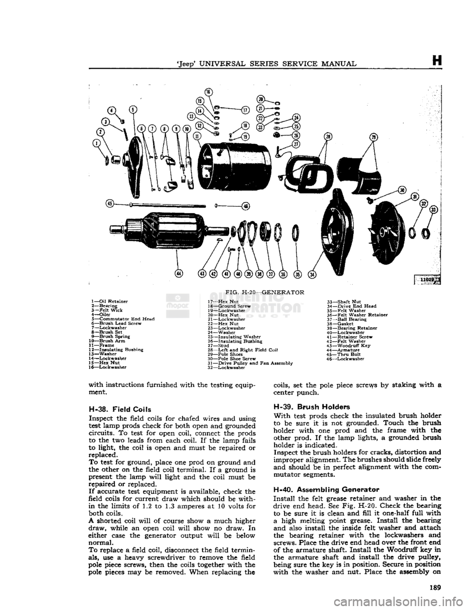
'Jeep'
UNIVERSAL
SERIES
SERVICE
MANUAL
H
U029p 1—
Oil
Retainer
2—
Bearing
3—
-Felt
Wick
4—
Oiler
5—
Commutator
End Head
6—
Brush
Lead
Screw
7—
Lockwasher
8—
Brush
Set
9—
Brush
Spring
10—
Brush
Arm
11—
Frame
12—
Insulating
Bushing
13—
Washer
14—
Lockwasher
15—
Hex
Nut
16—
Lockwasher
FIG.
H-20—GENERATOR
17—
Hex
Nut
18—
Ground
Screw
19—
Lockwasher
20—
Hex
Nut
21
—Lockwasher
22—
Hex
Nut
23—
Lockwasher
24—
Washer
25—
Insulating
Washer
26—
Insulating
Bushing
27—
Stud
28—
Left
and Right
Field
Coil
29— Pole Shoes
30— Pole Shoe Screw
31—
Drive
Pulley and Fan Assembly
3
2—Lockwasher
33—
Shaft
Nut
34—
Drive
End Head
35—
Felt
Washer
36—
Felt
Washer Retainer
37—
Ball
Bearing
38—
Gasket
39—
Bearing
Retainer
40—
Lockwasher
41—
Retainer
Screw
42—
-Felt
Washer
43—
Woodruff
Key
44—
Armature
45—
Thru
Bolt
4
6—Lockwasher
with
instructions furnished with the testing equip ment.
H-38.
Field
Coils
Inspect the field coils for chafed wires and using
test
lamp prods check for both open and grounded
circuits.
To
test
for open coil, connect the prods
to the two leads from each coil. If the lamp fails
to light, the coil is open and must be repaired or
replaced.
To
test
for ground, place one prod on ground and
the other on the field coil terminal. If a ground is present the lamp
will
light and the coil must be
repaired
or replaced.
If
accurate
test
equipment is available, check the
field coils for current draw which should be with
in
the limits of 1.2 to 1.3 amperes at 10 volts for both coils.
A shorted coil
will
of course show a much higher
draw,
while an open coil
will
show no draw. In
either case the generator output
will
be below
normal.
To
replace a field coil, disconnect the field termin
als,
use a heavy screwdriver to remove the field
pole
piece screws, then the coils
together
with the
pole
pieces may be removed. When replacing the coils, set the
pole
piece screws by staking with a
center punch.
H-39.
Brush
Holders
With
test
prods check the insulated brush holder
to be sure it is not grounded. Touch the brush
holder with one prod and the frame with the other prod. If the lamp lights, a grounded brush holder is indicated.
Inspect the brush holders for
cracks,
distortion and
improper
alignment. The brushes should slide freely
and
should be in perfect alignment with the com mutator
segments.
H-40.
Assembling Generator
Install
the felt grease retainer and washer in the
drive
end head. See Fig. H-20.
Check
the bearing to be sure it is clean and
fill
it one-half full with
a
high melting point grease.
Install
the bearing
and
also install the inside felt washer and attach
the bearing retainer with the lockwashers and
screws.
Place the drive end head over the front end
of the armature shaft.
Install
the Woodruff key in the armature shaft and install the drive pulley,
being sure the key is in position. Secure in position
with
the washer and nut. Place the assembly on 189
Page 190 of 376
H
ELECTRICAL
SYSTEM
FIG.
H-21—GROWLER
end so it rests on the pulley with the commutator
end up.
While
holding brushes clear of commutator with
the thumbs, place generator housing and field coils assembly in position, turning front end
bracket
so the dowel pin in housing enters
hole
in
end head. Place commutator end plate on shaft
and
install long frame screws.
When
reinstalling the generator on the engine, the
bracket
bolt torque wrench reading is 25 to 35 lb-ft. [3,4 a 4,8 kg-m.].
H-41.
CURRENT-VOLTAGE REGULATORS •
F4 Engine
H-42.
Description and
Operation
For
replacement,
voltage
regulator and generator must be matched for
voltage
and capacity, polarity,
and
common source of manufacture. Otherwise,
either a
loss
of ampere capacity or a burned out generator
will
result.
These
regulators are used with shunt-type gen
erators
and have three units each with a separate function to perform. These units are the circuit
breaker
unit, the
voltage
regulator unit, and the
current
limiting regulator unit.
H-43.
Circuit
Breaker
It
consists of
an
electromagnet and a set of contacts.
The
contacts are mounted with one on a stationary
bracket,
and the other on a movable armature
which
is controlled by the electromagnet. The movable contact is mounted on a spring arm so that as the contacts open and
close
a slight wiping
action is produced.
The
electromagnet of the circuit breaker has two
windings, one, the shunt coil which is connected across the generator output like a voltmeter and
the other a series coil connected in series with the
generator output like an ammeter.These two coils
are
wound in the same direction so that when the
generator is charging the battery, the magnetism
of the series coil increases the total magnetism.
When
the battery discharges back through the generator, the magnetism of the series coil is re versed and the magnetism of the two coils is
opposed.
This
results in a decreased
pull
on the
armature
and spring action
opens
the contacts.
10240
FIG.
H-22—PRESTOLITE VOLTAGE REGULATOR
1—
"ARM"
Terminal
2—
"FLD"
Terminal
3— "BAT"
Terminal
The
sequence of operation of the circuit breaker is
as follows:
When
the generator is not running, the contacts
are
open. When the generator is started, the
voltage
builds up at the armature terminal and in the shunt
coil
and as
soon
as it reaches the value for which
the circuit breaker is calibrated, there is sufficient magnetism created by the shunt coil to
pull
down
the armature, closing the contacts which auto
matically
connects the generator to the battery.
With
the contacts thus closed the current in the
series coil is flowing from the generator to the battery or in the same direction as the current in
the shunt coil, so that the
pull
on the armature is
increased
by the magnetism of the series coil.
When
the
engine
is stopped and the generator
loses
speed, the
voltage
falls, and as
soon
as the gener
ator
voltage
drops below the battery terminal vol
tage,
the current flows from the battery to the generator, reversing the direction of current in the
series coil so that the magnetism created by the series coil
opposes
and reduces the magnetism of
the shunt
coil.
This
reduces the
pull
on the
armature
to a point where spring action
opens
the contacts.
H-44.
Voltage
Regulator
The
function of the
voltage
regulator is to hold
the generated
voltage
at a predetermined value as 190
Page 191 of 376
'Jeep*
UNIVERSAL SERIES SERVICE
MANUAL
H
long as the circuit values allow the voltage to build
up to the operating voltage.
The
electromagnet of the voltage regulator unit has
a
winding of many turns of fine wire and is con
nected across the charging circuit so that the sys tem voltage controls the amount of magnetism.
The
contacts of the voltage regulator unit are con
nected in the generator field circuit so that the field
circuit
is completed through the contacts when they
are
closed and through a resistor when the contacts
are
opened.
When
the voltage rises to a predetermined value
there is sufficient magnetism created by the regu
lator
winding to
pull
the
armature
down.
This
opens
the contacts and inserts resistance in the field
cir
cuit
of the generator thus reducing the
field
current.
The
generated voltage immediately drops, which
reduces the
pull
on the
armature
to the point where
the spring closes the contacts. The output again
rises
and the cycle is repeated.
These
cycles occur at high enough frequencies to
hold the generated voltage at a constant value and
will
continue as long as the voltage of the circuit
is high enough to keep the voltage regulator unit
in
operation.
With
the addition of a current load great enough to lower the battery voltage below
the operating voltage of the unit, the contacts
will
remain
closed and the generator
will
maintain a
charging
rate as limited by its speed or the current
limiting
regulator.
Due
to the
effect
of heat on the operating
charac
teristics of regulator windings it is necessary to
compensate for the changes in coil resistance when
the regulator is operating under varying tempera
ture
conditions.
This
is accomplished through the
use of a nickel iron magnetic by-pass on the volt
age regulator unit.
This
shunt by-passes
some
of
the magnetic flux when the unit is cold and allows most of the flux to act on the armature when the
unit
is hot.
Thus
when the coil is hot and not as
efficient, the magnetic shunt reduces the amount of flux needed to vibrate the armature.
The
compensation is usually more than enough to
offset
the changes in regulator coil resistance due
to heat. The excess compensation allows the regu
lator
to operate at higher voltage under cold
operating conditions than under hot conditions.
This
is necessary as it requires a higher voltage to charge a battery with its internal resistance in
creased
by low temperatures.
H-45.
Current-Limiting
Regulator
The
function of the current-limiting regulator is to limit the output of the generator to its maxi
mum
safe output.
The
electromagnet of the current regulator unit
consists of
a
winding of heavy
wire
that is connected
in
series with the generator output. When the gen
erator
output reaches a predetermined value, the
current
in the winding produces enough magnetism
to overcome the spring tension and
pull
the
arma
ture
down.
This
opens
the contacts and inserts re
sistance in the field circuit of the generator.
With
the field current reduced by the resistance, the
generator output falls and there is no longer enough
magnetism to hold the contacts open. As soon as
the spring closes the contacts, the output rises and the cycle is repeated. These cycles occur at high
enough frequencies to limit the output to a mini
mum
fluctuation.
H-46.
Preliminary Inspection
a.
Wiring—Check
the wiring to see that it is prop
erly
connected to the generator.
b.
Generator
Performance—Make
sure the genera
tor operates correctly without the regulator in the
circuit.
Remove the armature and battery leads
from
the regulator and connect an ammeter be
tween them. Remove the field lead from the regu
lator
and while operating at idle speed touch the
field
lead
to the regulator base. Increase the speed slowly noting the charging rate.
CAUTION:
Do not increase the output above
the rated output of the generator.
If
the generator output
will
not build up inspect
the wiring harness for shorts and
opens
and remove the generator for an overhaul. To check the genera
tor circuit when a suitable ammeter is unavailable,
Fig.
H-19, disconnect the armature cable at the
regulator.
Connect one lead of
a
12v
test
lamp to the regulator terminal marked "armature" and with
the engine running, ground the other lead. Should
the
test
light
fail
to
burn
there is a fault either in the generator or regulator. To localize the fault, discon
nect both the
"Field"
and
"Armature"
cables at the generator. Connect a wire from the
"Field"
ter
minal
to ground and use a 60 watt, 110 volt
test
lamp
to ground the
"Armature"
terminal. If the
generator is charging satisfactorily the
test
lamp
will
glow
at approximately 1500 rpm. engine speed
and
the fault
will
be definitely localized in the
regulator.
c.
Incorrect Regulator—Make sui he regulator
is the correct type for use with the generator.
d.
Battery—Check
the specific gravity and termi
nal
voltage of the battery. If the \ ttery is not up
to specifications substitute temporarily
for
test
pur
poses
a fully charged battery of the same type and
capacity.
e. High Resistance Connections—Inspect the
wir
ing between the generator, regulator and battery for broken wires and high resistance connections.
Pay
special attention to the ground connections at
all
three units. Connect a reliable ammeter with 1-ampere graduations in series with the regulator
B-terminal
and the lead removed from this
terminal.
Run
the generator at a medium speed and
turn
on the lights or accessories until the ammeter shows a 10-ampere charging rate. At this charging rate
measure the voltage drop between the following
points using an accurate voltmeter graduated in
,1-volt divisions. The voltmeter should not show
a
reading above the maximum noted.
Generator
"A" terminal to regulator
"A"
terminal
—.1-volt maximum.
Generator
"F"
terminal to regulator
"F"
terminal
—.05-volt maximum.
Battery
terminal to regulator "B" terminal— .1-volt maximum.
Regulator
ground screw to generator frame— .03-volt maximum. 191
Page 192 of 376
H
ELECTRICAL
SYSTEM
Regulator
ground screw to battery ground post
—.03-volt maximum.
Generator
frame to battery ground post—.03-volt
maximum.
H-47.
Test Procedure
a.
Circuit
Breaker—Connect
an ammeter in series between the regulator B-terminal and the lead
wire
removed from that terminal. Connect a
voltmeter between the regulator
A-terminal
and the regulator mounting base. Disconnect the field lead
from
the regulator
F-terminal
and insert a variable resistance (3 amp., 50 ohm capacity) between the
lead
and the regulator terminal. Run the generator
at about 1000 generator rpm. Insert all the re
sistance in the field
circuit,
then slowly reduce the
resistance noting the voltage reading just before the change caused by the closing of the circuit
breaker.
Increase the charging rate to the figure
specified for the regulator being tested then reduce
the charging rate by inserting resistance in the
field
circuit.
Note
the voltmeter and ammeter
reading
just before the circuit breaker
opens
and
the ammeter reading drops to zero. The closing voltage and the opening voltage or current should
be within the limits specified. An accurate method
for noting the exact instant of the opening or closing
of the circuit breaker is to connect a headphone (2000 ohms or higher) to the battery and armature
terminals
of the regulator. When the contacts
open or close a
click
will
be
heard
in the headphones.
To
adjust the closing voltage change the armature
spring
tension by bending the hanger at the lower end of the spring. Increase the spring tension to
raise
the closing voltage or decrease the tension
to lower the closing voltage. To adjust the opening voltage raise or lower the stationary contact
keeping the contacts perfectly aligned. Increasing
the contact gap lowers the opening
'
voltage.
Change
the contact gap by expanding or contract
ing the stationary contact bracket, keeping the
contacts aligned. Do not adjust the gap between
the contacts to less than the specified minimum.
b.
Voltage Regulator—Connect the ammeter as in
step
a. Connect the voltmeter between the regulator
B-terminal
and the regulator base. Remove the
variable
resistance from the field
circuit.
Run the
generator at
half
output for 15 minutes to bring
the regulator to normal operating temperature.
Keep
the cover on the regulator during the
warm-
up period and also when taking readings.
Stop the engine then bring it up to approximately 2500 generator rpm. Adjust the amperage to
half
maximum
output by turning on lights or accessor
ies and then
note
the voltmeter reading.
This
read
ing should be within the limits specified for the voltage regulator operation. To adjust the oper
ating voltage change the
armature
spring tension by
bending the hanger at the lower end of the
arma
ture
spring. After each adjustment
stop
the engine then restart it.
Bring
it up to speed and adjust the
current
before taking a reading. In order to obtain
an
accurate indication of the operation of the volt
age regulator unit connect a headphone (2000 ohm
or
higher) between the
F-terminal
and ground to
pick
up the sound of the opening and closing of the
contacts. The clicks should be regular and clear without irregularities or missing. If the
tone
is not
clear
and regular remove the regulator cover and
inspect the contacts. The contacts should be flat
and
not burned excessively and should be aligned
to make
full
face contact. If the contacts need
cleaning refer to paragraph d for the method.
c.
Current
Regulator—Connect the regulator and the
test
equipment as in
step
b. Running the generator at approximately 3000 generator rpm.,
turn
on lights and accessories so that the generator must charge at maximum rate. The ammeter should give a reading within the limits specified.
To
adjust opening amperage, change the armature
spring
tension by bending the hanger at the lower
end of the armature spring. After each adjustment,
stop
the engine, then restart it.
Bring
the engine up to speed and take an ammeter reading. Keep
the cover on the regulator when taking
these
readings.
Connect
a headphone (2000 ohms or higher) be
tween the regulator
F-terminal
and ground to pick
up the sound of opening and closing of the contacts.
Clear,
regular clicks should be heard over the
headphones; they should not be
irregular
or missing.
If
the
tone
is not clear and regular remove the
regulator cover and inspect the contacts. The
contacts should be flat and not burned excessively
and
should be aligned to make
full
face contact. If
the contacts need cleaning refer to paragraph d.
below for the method.
d.
Contacts—Inspect the contacts on all three
units.
In normal use the contacts
will
become
grayed.
If the contacts are burned or dirty or if they are not smooth, file the contacts with a #6
American,
Swiss cut, equalling file. Move the file
parallel
and lengthwise to the armature.
File
just
enough so that the contacts present a smooth
sur
face toward each other. It is not necessary to remove every trace of pitting. After filing, dampen
a
piece of linen or lintless bond tape in refined
carbon
tetrachloride and draw the tape between
the contacts. Repeat with a dry piece of tape. Use
clean
tape for each set of contacts.
e. Recheck—Operate the unit at
half
maximum
output for five minutes with the cover on the regu
lator.
Repeat the testing procedure for all units as described in a, b, c above. Be sure cover is on regu
lator
when taking readings.
H-48.
Quick
Checks
H-49.
Low Charging Rate with a
Fully
Charged
Battery
A
fully charged battery and a low charging rate
indicates normal regulator operation.
A
further check of the regulator operation can be
made by using the starting motor for 5 to 10
seconds with the ignition switch in the "off" posi tion.
Then
start the engine and operate at a genera
tor speed of 2500 to 3000 rpm. The charging rate should rise to its maximum value then taper off to
a
minimum charge as the battery becomes charged.
H-50.
High Charging Rate with a
Fully
Charged
Battery
This
is usually an indication that the voltage regu
lator
is not operating correctly. The high voltage 192
Page 194 of 376
H
ELECTRICAL
SYSTEM H-61.
Test Nine
Operate
at a medium speed with the jumper re moved. Remove the regulator cover and hold the
voltage
regulator contacts closed.
a.
Voltage builds up—voltage regulator contacts
burned
or dirty or incorrect regulator setting.
Clean
the contacts and adjust the regulator as in
Par.
H-47d.
b.
Voltage
does
not build up—clean contacts and
repeat
test.
If the
voltage
still
does
not build up, see
test
10.
H-62.
Test Ten
Remove the regulator cover and hold the current
regulator contacts closed.
a.
Voltage builds up—current regulator contacts
burned
or dirty or incorrect regulator setting.
Clean
the contacts and adjust the regulator as in
Par.
H-47d.
b.
Voltage
does
not build up—clean the contacts
and
repeat the
test.
If the
voltage
still
does
not
build
up remove the regulator for an overhaul.
H-63. ALTERNATOR CHARGING SYSTEM
Most vehicles have, as standard equipment, a 35-
amp.,
12-volt, negative ground alternator and a
transistorized
voltage
regulator.
The
alternator charging circuit consists of the
battery, alternator,
voltage
regulator, ignition
switch,
and charge indicator light.
An
alternator differs from a conventional DC
shunt generator in that the armature is stationary,
and
is called the stator, while the field rotates,
and
is called the rotor.
With
the alternator con
struction,
the higher current values involved in
the stator may be conducted to the external circuit through fixed leads and connections, rather than
through a rotating commutator and brushes, as in the DC generator.
The
alternator employs a three-phase stator
winding. The rotor consists of a field coil encased
between
six poled interleaved sections, producing
a
twelve
pole
magnetic field with alternator north
and
south poles. By rotating the rotor inside the stator, an alternating current is induced in the stator windings.
This
alternating current is
changed to direct current by
diodes
and conducted
to the output terminal of the alternator.
Six
silicon
diode
rectifiers act as electrical one-way valves.
Three
of the
diodes
have negative polarity
and
are grounded. The other three
diodes
have
positive polarity and connected to the output
terminal.
In all alternators discussed in this
manual,
the
diodes
are pressed into heat sinks.
There
are two heat sinks, one positive and the
other negative.
Since
the
diodes
have a high resistance to the
flow of
current
in one direction and a low resistance
in
the
opposite
direction, they are connected in a
manner
which allows current to flow from the
alternator to the battery in the low resistance
direction.
The high resistance in the
opposite
direction prevents the flow of current from the
battery to the alternator. Because of this feature,
no
circuit
breaker
is
required
between
the alternator
and
the battery.
Residual
magnetism in the rotor field
poles
is
negligible. Therefore the starting field current must be supplied by the battery. It is connected
to the field winding through the ignition switch
and
charge indicator lamp.
As
in the DC shunt generator, the alternator
voltage
is regulated by varying the field current.
In
these
alternator systems, this is accomplished
electronically in the transistorized
voltage
reg
ulator.
No current regulator is required since all
alternators have self-limiting current character
istics.
The
entire DC output of the alternator has to pass
through the isolation diode. The isolation
diode
is
not essential for rectification. Its purpose is threefold.
It
provides automatic solid
state
switch for
illumi
nating the alternator charge
-
discharge indicator
light when the alternator is not charging properly.
It
automatically connects the
voltage
regulator to
the alternator and battery when the alternator is
operating.
It
eliminates electrical leakage across the alternator
diodes
so that leakage is negligible when the vehicle
is not in use.
The
isolation
diode
is mounted in a separate alumi
num
heat sink. The 35-amp. alternator has a single
silicon diode. The alternator is designed to supply the electrical demands of the battery and the
accessory circuits through a wide range of
engine
speeds. The alternator is lighter and more compact
than
a conventional DC shunt generator of com
parable
electrical size.
The
principal
components of the alternator are
the stator, the rotor, the slip ring end head, the
drive
end head, the
diode
rectifiers, and the isolation diode.
a.
The stator consists of a laminated iron core on
which
the three-phase windings are wound in
slots
around
the inside circumference. A
pair
of leads
are
connected to each of the three points of the
winding. One of each
pair
of leads connects to a
negative
diode
rectifier and one to a positive
diode
rectifier.
b.
The rotor consists of a single field coil encased
between
two six-fingered, interleaved iron sections assembled to the shaft. The two ends of the field
coil
are connected to two slip rings which are in
sulated from each other and from the shaft.
c. The slip ring end head supports the rectifier heat sinks; a prelubricated sealed
ball
bearing, in
which
the rotor shaft rotates; and the brush holders
and
brushes.
d.
The drive end head supports a prelubricated
sealed
ball
bearing in which the drive end of the rotor shaft rotates.
e. The
diode
rectifiers are pressed in the rectifier brackets or heat sinks and are connected to the
stator leads.
f. The isolation
diode
is pressed in the aluminum heat sink mounted to the
rear
of the alternator. The
complete assembly is covered with a red insulating coating.
For
repairing the alternator, many of its major components are furnished as complete assemblies
including:
complete brush assembly which requires 194
Page 195 of 376
'Jeep*
UNIVERSAL
SERIES SERVICE
MANUAL
H
no soldering or unsoldering of leads; two complete
rectifying
diode assemblies
which
eliminate the need
for removing and replacing individual diodes; a
corpplete isolation diode assembly; and a rotor
assembly complete with shaft,
pole
pieces, field
coil,
and slip rings.
The
transistorized
voltage
regulator is an electronic
switching device. It
senses
the
voltage
appearing
at the auxiliary terminal of the alternator and
supplies the necessary field current for maintaining
the system
voltage
at the output terminal. The
output current is determined by the battery electri
cal
load; such as headlights, heater, etc.
The
transistorized
voltage
regulator is a sealed
unit,
has no adjustments, and must be replaced
as a complete unit.
H-64. ALTERNATOR
PRECAUTIONS
The
following precautions must be observed to
prevent damage to the alternator and regulator.
a.
Never reverse battery connections. Always
check
the battery polarity with a voltmeter before
any
connections are made to be sure that all con
nections correspond to the battery ground polarity of the vehicle.
b.
Booster batteries for starting must be properly
connected. Make sure that the negative cable of
the booster battery is connected to the negative
terminal
of the battery in the vehicle. The positive
cable of the booster battery should be connected
to the positive terminal of the battery in the
vehicle.
c.
Disconnect the battery cables before using a fast charger.
d.
Never use a fast charger as a booster for
starting
the vehicle.
e.
Never disconnect the
voltage
regulator while
the
engine
is running.
f.
Do not ground the alternator output terminal.
g.
Do not operate the alternator on an open
circuit
with
the field energized.
h.
Do not attempt to polarize an alternator.
These
precautions are stated here as an aid to
service
personnel. They are also restated at appro
priate
places in the
text
of this section of the
manual.
H-65. ALTERNATOR
CHARGING
SYSTEM SERVICE
Important:
All alternator
tests
for the 35, 40 and
55 amp alternator are the same, however, there is a
difference
between
the location of the various ter
minals
and field current specifications. The field
current
of the 35 amp alternator should be 1.7 to 2.3 amps, 40 and 55 amp alternators should be 1.8
to 2.4 amps, with
full
battery
voltage
applied to
the filed coil. Disassembly and assembly procedures
are
the same for all three alternators.
Terminal
locations and wire harness color
codes
for the 35,
40 and 55 amp alternator are shown in Fig. H-38.
H-66.
Service Diagnosis
In
diagnosing a suspected malfunction of the
alternator
charging system, consideration must
be given to the complete electrical power plant of the vehicle; including the alternator, regulator,
ignition switch, charge indicator lamp, battery,
and
all associated wiring. If it is suspected that the
alternator
is not fully charging the battery and
fulfilling
the electrical requirements of the electrical
system, several checks should be made before
checking
the alternator itself:
Note:
Whenever service is required in connection
with
an alternator problem, the first
step
should be to verify that the wiring harness hook-up is correct
as indicated in Fig. H-38.
a.
Test the condition of the battery and
state
of
charge
(Par. H-2).
If the battery is not fully charged
and
in
good
condition, use a replacement battery
for making alternator system
tests.
Caution:
Make certain that the negative battery
post
is connected to ground when making the
battery installation. Serious damage to the alter
nator
can result if battery polarity is reversed.
b.
Check
fan belt for proper tension (Par.
C-27).
Caution:
To increase belt tension, apply pressure
to alternator front housing only as permanent damage can result if pressure is applied to
rear
housing.
H-67.
Alternator In Vehicle Tests
The
following
tests
are made with the alternator
in
the vehicle with output and regulator connec
tions maintained to the alternator except as noted
in
Fig. H-27 and H-28. The field plug and
voltage
regulator are disconnected for
these
tests.
The
tests
are given in proper order and detail in the
following paragraphs.
a.
Isolation Diode Test: To determine if the isola
tion diode is open or shorted, refer to Par. H-69.
b.
Alternator Output Test: To isolate the trouble
to the alternator or regulator, refer to Par. H-70.
c.
Alternator
Field
Circuit
Test: To determine the condition of the field
circuit
(brushes and rotor),
refer
to Par. H-73.
d.
Brush
Insulation
and Continuity
Test:
To deter
mine the condition of the
brush,
refer to
Par.
H-75.
e.
Rotor In-Vehicle Test: To determine whether
the rotor coil is open or shorted, refer to
Par.
H-73.
f. Any further
tests
must be conducted with the
alternator
removed and disassembled. When this
is done, the condition of the rotor, the rectifying
and
isolation diodes, and the stator can be further
tested.
A
commercial alternator tester Sun
Electric
Model
VAT-20
or equivalent can be used to make all
necessary
tests
on the alternator system. If a com
mercial
tester is used, follow the recommended
testing procedure outlined by the tester manu
facturer.
If
a commercial tester is not available, follow the
testing procedure as outlined in this manual.
H-68.
Test Equipment
a.
Volt Ampere Tester such as Sun
Electric
Model
VAT-20
or equivalent with meter ranges as shown
in
the following list can be used. 195