warning lights JEEP COMPASS 2019 Owner handbook (in English)
[x] Cancel search | Manufacturer: JEEP, Model Year: 2019, Model line: COMPASS, Model: JEEP COMPASS 2019Pages: 362, PDF Size: 6.23 MB
Page 77 of 362
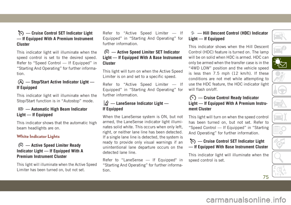
— Cruise Control SET Indicator Light
— If Equipped With A Premium Instrument
Cluster
This indicator light will illuminate when the
speed control is set to the desired speed.
Refer to “Speed Control — If Equipped” in
“Starting And Operating” for further informa-
tion.
— Stop/Start Active Indicator Light —
If Equipped
This indicator light will illuminate when the
Stop/Start function is in “Autostop” mode.
— Automatic High Beam Indicator
Light — If Equipped
This indicator shows that the automatic high
beam headlights are on.
White Indicator Lights
— Active Speed Limiter Ready
Indicator Light — If Equipped With A
Premium Instrument Cluster
This light will illuminate when the Active Speed
Limiter has been turned on, but not set.
Refer to “Active Speed Limiter — If
Equipped” in “Starting And Operating” for
further information.
— Active Speed Limiter SET Indicator
Light — If Equipped With A Base Instrument
Cluster
This light will turn on when the Active Speed
Limiter is on and set to a specific speed.
Refer to “Active Speed Limiter — If
Equipped” in “Starting And Operating” for
further information.
— LaneSense Indicator Light —
If Equipped
When the LaneSense system is ON, but not
armed, the LaneSense indicator light illumi-
nates solid white. This occurs when only left,
right, or neither lane line has been detected.
If a single lane line is detected, the system is
ready to provide only visual warnings if an
unintentional lane departure occurs on the
detected lane line.
Refer to “LaneSense — If Equipped" in
“Starting And Operating” for further informa-
tion.
— Hill Descent Control (HDC) Indicator
Light — If Equipped
This indicator shows when the Hill Descent
Control (HDC) feature is turned on. The lamp
will be on solid when HDC is armed. HDC can
only be armed when the transfer case is in the
“4WD LOW” position and the vehicle speed
is less then 7.5 mph (12 km/h). If these
conditions are not met while attempting to
use the HDC feature, the HDC indicator light
will flash on/off.
— Cruise Control Ready Indicator
Light — If Equipped With A Premium Instru-
ment Cluster
This light will turn on when the speed control
has been turned on, but not set. Refer to
“Speed Control — If Equipped” in “Starting
And Operating” for further information.
— Cruise Control SET Indicator Light
— If Equipped With Base Instrument Cluster
This indicator light will illuminate when the
speed control is set.
75
Page 78 of 362
Refer to “Speed Control — If Equipped” in
“Starting And Operating” for further informa-
tion.
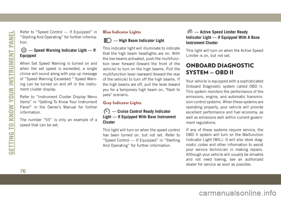
— Speed Warning Indicator Light — If
Equipped
When Set Speed Warning is turned on and
when the set speed is exceeded, a single
chime will sound along with pop up message
of “Speed Warning Exceeded.” Speed Warn-
ing can be turned on and off in the instru-
ment cluster display.
Refer to “Instrument Cluster Display Menu
Items” in “Getting To Know Your Instrument
Panel” in the Owner’s Manual for further
information.
The number “55” is only an example of a
speed that can be set.
Blue Indicator Lights
— High Beam Indicator Light
This indicator light will illuminate to indicate
that the high beam headlights are on. With
the low beams activated, push the multifunc-
tion lever forward (toward the front of the
vehicle) to turn on the high beams. Pull the
multifunction lever rearward (toward the rear
of the vehicle) to turn off the high beams. If
the high beams are off, pull the lever toward
you for a temporary high beam on, "flash to
pass" scenario.
Gray Indicator Lights
— Cruise Control Ready Indicator
Light — If Equipped With Base Instrument
Cluster
This light will turn on when the speed control
has been turned on, but not set. Refer to
“Speed Control — If Equipped” in “Starting
And Operating” for further information.
— Active Speed Limiter Ready
Indicator Light — If Equipped With A Base
Instrument Cluster
This light will turn on when the Active Speed
Limiter is on, but not set.
ONBOARD DIAGNOSTIC
SYSTEM — OBD II
Your vehicle is equipped with a sophisticated
Onboard Diagnostic system called OBD II.
This system monitors the performance of the
emissions, engine, and automatic transmis-
sion control systems. When these systems are
operating properly, your vehicle will provide
excellent performance and fuel economy, as
well as emissions well within current govern-
ment regulations.
If any of these systems require service, the
OBD II system will turn on the Malfunction
Indicator Light (MIL). It will also store diag-
nostic codes and other information to assist
your service technician in making repairs.
Although your vehicle will usually be drivable
and not need towing, see an authorized
dealer for service as soon as possible.
GETTING TO KNOW YOUR INSTRUMENT PANEL
76
Page 93 of 362
Modes Of Operation
Three selectable modes of operation are
available in the Uconnect System. Refer to
“Uconnect Settings” in “Multimedia” in the
Owner’s Manual for further information.
Blind Spot Alert Lights Only (Default Setting)
When operating in Blind Spot Alert mode, the
BSM system will provide a visual alert in the
appropriate side view mirror based on a de-
tected object. However, when the system is
operating in Rear Cross Path (RCP) mode, the
system will respond with both visual and
audible alerts when a detected object is pres-
ent. Whenever an audible alert is requested,
the radio is muted.
Blind Spot Alert Lights/Chime
When operating in Blind Spot Alert Lights/
Chime mode, the BSM system will provide a
visual alert in the appropriate side view mirror
based on a detected object. If the turn signal
is then activated, and it corresponds to an
alert present on that side of the vehicle, an
audible chime will also be sounded. When-
ever a turn signal and detected object are
present on the same side at the same time,both the visual and audible alerts will be
issued. In addition to the audible alert the
radio (if on) will also be muted.
NOTE:
Whenever an audible alert is requested by the
BSM system, the radio is also muted.
When the system is in RCP, the system shall
respond with both visual and audible alerts
when a detected object is present. Whenever
an audible alert is requested, the radio vol-
ume is reduced. Turn/hazard signal status is
ignored; the RCP state always requests the
chime.
Blind Spot Alert Off
When the BSM system is turned off there will
be no visual or audible alerts from either the
BSM or RCP systems.
NOTE:
The BSM system will store the current oper-
ating mode when the vehicle is shut off. Each
time the vehicle is started the previously
stored mode will be recalled and used.Blocked Sensor
If the system detects degraded performance
due to contamination or foreign objects, a
message will warn you of a blocked sensor
and the warning indicators in side view mir-
rors will be illuminated. The warning indica-
tors will remain illuminated until blockage
clearing conditions are met. First clear the
fascia area around the sensors of the block-
age. After removing the blockage, reset the
system by cycling the ignition from ON to OFF
and then back ON.
Forward Collision Warning (FCW)
With Mitigation — If Equipped
Forward Collision Warning (FCW)
With Mitigation Operation
The Forward Collision Warning (FCW) system
with mitigation provides the driver with au-
dible warnings, visual warnings (within the
instrument cluster display), and may apply a
brake jerk to warn the driver when it detects a
potential frontal collision. The warnings and
limited braking are intended to provide the
driver with enough time to react, avoid or
mitigate the potential collision.
91
Page 113 of 362
The Passenger Air Bag DISABLE Feature
consists of the following:
• Occupant Restraint Controller (ORC)
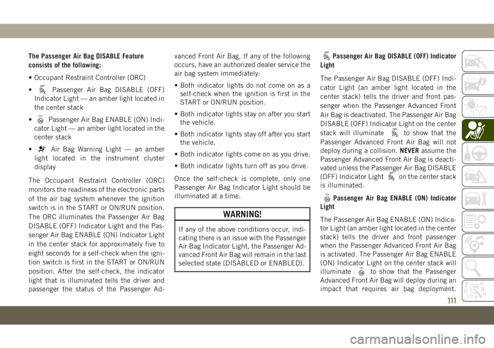
•
Passenger Air Bag DISABLE (OFF)
Indicator Light — an amber light located in
the center stack
•
Passenger Air Bag ENABLE (ON) Indi-
cator Light — an amber light located in the
center stack
•
Air Bag Warning Light — an amber
light located in the instrument cluster
display
The Occupant Restraint Controller (ORC)
monitors the readiness of the electronic parts
of the air bag system whenever the ignition
switch is in the START or ON/RUN position.
The ORC illuminates the Passenger Air Bag
DISABLE (OFF) Indicator Light and the Pas-
senger Air Bag ENABLE (ON) Indicator Light
in the center stack for approximately five to
eight seconds for a self-check when the igni-
tion switch is first in the START or ON/RUN
position. After the self-check, the indicator
light that is illuminated tells the driver and
passenger the status of the Passenger Ad-vanced Front Air Bag. If any of the following
occurs, have an authorized dealer service the
air bag system immediately:
• Both indicator lights do not come on as a
self-check when the ignition is first in the
START or ON/RUN position.
• Both indicator lights stay on after you start
the vehicle.
• Both indicator lights stay off after you start
the vehicle.
• Both indicator lights come on as you drive.
• Both indicator lights turn off as you drive.
Once the self-check is complete, only one
Passenger Air Bag Indicator Light should be
illuminated at a time.
WARNING!
If any of the above conditions occur, indi-
cating there is an issue with the Passenger
Air Bag Indicator Light, the Passenger Ad-
vanced Front Air Bag will remain in the last
selected state (DISABLED or ENABLED).
Passenger Air Bag DISABLE (OFF) Indicator
Light
The Passenger Air Bag DISABLE (OFF) Indi-
cator Light (an amber light located in the
center stack) tells the driver and front pas-
senger when the Passenger Advanced Front
Air Bag is deactivated. The Passenger Air Bag
DISABLE (OFF) Indicator Light on the center
stack will illuminate
to show that the
Passenger Advanced Front Air Bag will not
deploy during a collision.NEVERassume the
Passenger Advanced Front Air Bag is deacti-
vated unless the Passenger Air Bag DISABLE
(OFF) Indicator Light
on the center stack
is illuminated.
Passenger Air Bag ENABLE (ON) Indicator
Light
The Passenger Air Bag ENABLE (ON) Indica-
tor Light (an amber light located in the center
stack) tells the driver and front passenger
when the Passenger Advanced Front Air Bag
is activated. The Passenger Air Bag ENABLE
(ON) Indicator Light on the center stack will
illuminate
to show that the Passenger
Advanced Front Air Bag will deploy during an
impact that requires air bag deployment.
111
Page 117 of 362
WARNING!
• Children 12 years or younger should
always ride buckled up in the rear seat of
a vehicle with a rear seat.
Knee Impact Bolsters
The Knee Impact Bolsters help protect the
knees of the driver and front passenger, and
position the front occupants for improved
interaction with the front air bags.
WARNING!
• Do not drill, cut, or tamper with the knee
impact bolsters in any way.
• Do not mount any accessories to the
knee impact bolsters such as alarm
lights, stereos, citizen band radios, etc.
Supplemental Seat-Mounted Side Air Bags
(SABs) (If Equipped)
Your vehicle may be equipped with Supple-
mental Seat-Mounted Side Air Bags (SABs).If your vehicle is equipped with Supplemen-
tal Seat-Mounted Side Air Bags (SABs),
please refer to the information below.
Supplemental Seat-Mounted Side Air Bags
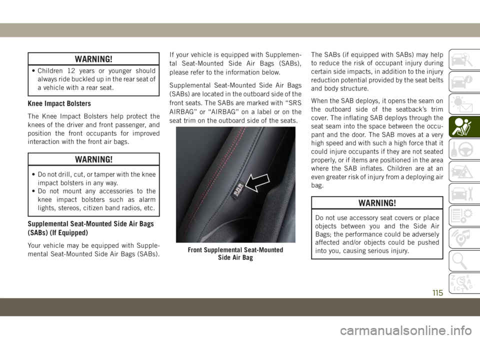
(SABs) are located in the outboard side of the
front seats. The SABs are marked with “SRS
AIRBAG” or “AIRBAG” on a label or on the
seat trim on the outboard side of the seats.The SABs (if equipped with SABs) may help
to reduce the risk of occupant injury during
certain side impacts, in addition to the injury
reduction potential provided by the seat belts
and body structure.
When the SAB deploys, it opens the seam on
the outboard side of the seatback’s trim
cover. The inflating SAB deploys through the
seat seam into the space between the occu-
pant and the door. The SAB moves at a very
high speed and with such a high force that it
could injure occupants if they are not seated
properly, or if items are positioned in the area
where the SAB inflates. Children are at an
even greater risk of injury from a deploying air
bag.
WARNING!
Do not use accessory seat covers or place
objects between you and the Side Air
Bags; the performance could be adversely
affected and/or objects could be pushed
into you, causing serious injury.
Front Supplemental Seat-Mounted
Side Air Bag
115
Page 121 of 362
see your doctor. If these particles settle on
your clothing, follow the garment manufac-
turer’s instructions for cleaning.
Do not drive your vehicle after the air bags
have deployed. If you are involved in another
collision, the air bags will not be in place to
protect you.
WARNING!
Deployed air bags and seat belt preten-
sioners cannot protect you in another col-
lision. Have the air bags, seat belt preten-
sioners, and the seat belt retractor
assemblies replaced by an authorized
dealer immediately. Also, have the Occu-
pant Restraint Controller System serviced
as well.
NOTE:
• Air bag covers may not be obvious in the
interior trim, but they will open during air
bag deployment.
• After any collision, the vehicle should be
taken to an authorized dealer immediately.
Enhanced Accident Response System
In the event of an impact, if the communica-
tion network remains intact, and the power
remains intact, depending on the nature of
the event, the ORC will determine whether to
have the Enhanced Accident Response Sys-
tem perform the following functions:
• Cut off fuel to the engine (If Equipped)
• Cut off battery power to the electric motor
(If Equipped)
• Flash hazard lights as long as the battery
has power
• Turn on the interior lights, which remain on
as long as the battery has power or for 15
minutes from the intervention of the En-
hanced Accident Response System.
• Unlock the power door locks.
Your vehicle may also be designed to perform
any of these other functions in response to
the Enhanced Accident Response System:
• Turn off the Fuel Filter Heater, Turn off the
HVAC Blower Motor, Close the HVAC Circu-
lation Door• Cut off battery power to the:
– Engine
– Electric Motor (if equipped)
– Electric power steering
– Brake booster
– Electric park brake
– Automatic transmission gear selector
– Horn
– Front wiper
– Headlamp washer pump
NOTE:
After an accident, remember to cycle the
ignition to the STOP (OFF/LOCK) position
and remove the key from the ignition switch
to avoid draining the battery. Carefully check
the vehicle for fuel leaks in the engine com-
partment and on the ground near the engine
compartment and fuel tank before resetting
the system and starting the engine. If there
are no fuel leaks or damage to the vehicle
electrical devices (e.g. headlights) after an
accident, reset the system by following the
procedure described below. If you have any
doubt, contact an authorized dealer.
119
Page 123 of 362
Customer ActionCustomer Will See
NOTE:
Each step MUST BE
held for at least
two seconds
12. Turn ignition
MAR/ACC/ON/RUN.
(Entire sequence
needs to be
completed within
one minute or
sequence will need
to be repeated).System is now reset
and the engine may
be started.
Turn hazard flashers
OFF (Manually).
If a reset procedure step is not completed
within 60 seconds, then the turn signal lights
will blink and the reset procedure must be
performed again in order to be successful.
Maintaining Your Air Bag System
WARNING!
• Modifications to any part of the air bag
system could cause it to fail when you
need it. You could be injured if the air
bag system is not there to protect you.
Do not modify the components or wiring,
including adding any kind of badges or
stickers to the steering wheel hub trim
cover or the upper passenger side of the
instrument panel. Do not modify the
front bumper, vehicle body structure, or
add aftermarket side steps or running
boards.
• It is dangerous to try to repair any part of
the air bag system yourself. Be sure to
tell anyone who works on your vehicle
that it has an air bag system.
• Do not attempt to modify any part of your
air bag system. The air bag may inflate
accidentally or may not function prop-
erly if modifications are made. Take your
vehicle to an authorized dealer for any
air bag system service. If your seat, in-
cluding your trim cover and cushion,
WARNING!
needs to be serviced in any way (includ-
ing removal or loosening/tightening of
seat attachment bolts), take the vehicle
to an authorized dealer. Only manufac-
turer approved seat accessories may be
used. If it is necessary to modify the air
bag system for persons with disabilities,
contact an authorized dealer.
Event Data Recorder (EDR)
This vehicle is equipped with an event data
recorder (EDR). The main purpose of an EDR
is to record, in certain crash or near crash-like
situations, such as an air bag deployment or
hitting a road obstacle, data that will assist in
understanding how a vehicle’s systems per-
formed. The EDR is designed to record data
related to vehicle dynamics and safety sys-
tems for a short period of time, typically
30 seconds or less.
121
Page 142 of 362
WARNING!
interference. If your floor mat interferes
with the operation of any pedal, or is not
secure to the floor, remove the floor mat
from the vehicle and place the floor mat
in your trunk.
• ONLY use the passenger’s side floor mat
on the passenger’s side floor area.
• ALWAYS make sure objects cannot fall or
slide into the driver’s side floor area
when the vehicle is moving. Objects can
become trapped under accelerator,
brake, or clutch pedals and could cause
a loss of vehicle control.
• NEVER place any objects under the floor
mat (e.g., towels, keys, etc.). These ob-
jects could change the position of the
floor mat and may cause interference
with the accelerator, brake, or clutch
pedals.
• If the vehicle carpet has been removed
and re-installed, always properly attach
carpet to the floor and check the floor
mat fasteners are secure to the vehicle
WARNING!
carpet. Fully depress each pedal to
check for interference with the accelera-
tor, brake, or clutch pedals then re-
install the floor mats.
• It is recommended to only use mild soap
and water to clean your floor mats. After
cleaning, always check your floor mat
has been properly installed and is se-
cured to your vehicle using the floor mat
fasteners by lightly pulling mat.
Periodic Safety Checks You Should Make
Outside The Vehicle
Tires
Examine tires for excessive tread wear and
uneven wear patterns. Check for stones,
nails, glass, or other objects lodged in the
tread or sidewall. Inspect the tread for cuts
and cracks. Inspect sidewalls for cuts,
cracks, and bulges. Check the wheel nuts for
tightness. Check the tires (including spare)
for proper cold inflation pressure.
Lights
Have someone observe the operation of brake
lights and exterior lights while you work the
controls. Check turn signal and high beam
indicator lights on the instrument panel.
Door Latches
Check for proper closing, latching, and lock-
ing.
Fluid Leaks
Check area under the vehicle after overnight
parking for fuel, coolant, oil, or other fluid
leaks. Also, if gasoline fumes are detected or
if fuel, or brake fluid leaks are suspected. The
cause should be located and corrected imme-
diately.
SAFETY
140
Page 146 of 362
WARNING!
N-Go in the ACC or ON/RUN mode. A
child could operate power windows,
other controls, or move the vehicle.
• Do not leave children or animals inside
parked vehicles in hot weather. Interior
heat build-up may cause serious injury
or death.
NOTE:
Engine start up in very low ambient tempera-
ture could result in evident white smoke. This
condition will disappear as the engine warms
up.
CAUTION!
The engine is allowed to crank as long as
30 seconds. If the engine fails to start
during this period, please wait at least two
minutes for the starter to cool before re-
peating start procedure.
Normal Starting Procedure — Keyless
Enter-N-Go
Observe the instrument panel cluster lights
when starting the engine.
NOTE:
Normal starting of either a cold or a warm
engine is obtained without pumping or press-
ing the accelerator pedal.
1. Always apply the parking brake.
2. Press and hold the brake pedal while
pushing the ENGINE START/STOP button
once.
NOTE:
A delay of the start of up to five seconds is
possible under very cold conditions. The
“Wait to Start” telltale will be illuminated
during the pre-heat process, When the
engine Wait To Start light goes off the
engine will automatically crank.
CAUTION!
If the “Water in Fuel Indicator Light” re-
mains on, DO NOT START the engine be-
fore the water is drained from the fuel
filters to avoid engine damage.
3. The system will automatically engage the
starter to crank the engine. If the vehicle
fails to start, the starter will disengage
automatically after 30 seconds.
4. If you wish to stop the cranking of the
engine prior to the engine starting, push
the button again.
5. Check that the oil pressure warning light
has turned off.
6. Release the parking brake.
STARTING AND OPERATING
144
Page 186 of 362
Emergency Gas Can Refueling
Most gas cans will not open the flapper door.
A funnel is provided to open the flapper door
to allow emergency refueling with a gas can.
1. Retrieve funnel from the rear cargo area.
2. Insert funnel into same filler pipe opening
as the fuel nozzle.
3. Ensure funnel is inserted fully to hold
flapper door open.
4. Pour fuel into funnel opening.
5. Remove funnel from filler pipe, clean off
prior to putting back in the spare tire
storage area.
NOTE:
• When the fuel nozzle “clicks” or shuts off,
the fuel tank is full.WARNING!
• Never have any smoking materials lit in
or near the vehicle when the fuel door is
open or the tank is being filled.
• Never add fuel when the engine is run-
ning. This is in violation of most coun-
tries regulations and may cause the
“Malfunction Indicator Light” to turn
on.
• Do not apply any object/cap to the end of
the filler which is not provided for the
car. The use of non-compliant objects/
plugs could cause a pressure increase
inside the tank, resulting in dangerous
situations.
• A fire may result if fuel is pumped into a
portable container that is inside of a
vehicle. You could be burned. Always
place fuel containers on the ground
while filling.
Adblue (UREA) — If Equipped
The vehicle is equipped with an UREA injec-
tion system and Selective Catalytic Reduc-
tion to meet emission standards. These two
systems ensure compliance with the diesel
emissions requirements; at the same, they
ensure fuel-efficiency, handling, torque and
power. For messages and system warnings,
refer to the "Warning Lights And Messages" in
the "Getting To Know Your Instrument Panel"
section. AdBlue (UREA) is a very stable prod-
uct with a long shelf life. Stored at tempera-
tures LOWER than 90 °F (32 °C), it has a
shelf life of at least one year. For more infor-
mation on the AdBlue liquid type, see the
“Fluids and lubricants” in the “Technical
specifications” section. The vehicle is
equipped with an automatic AdBlue heating
system when the engine starts allowing the
system to work correctly at temperatures
lower than 12 °F (-11 °C).
NOTE:
AdBlue freezes at temperatures lower than
12 °F (-11 °C).
STARTING AND OPERATING
184