lock JEEP COMPASS 2020 Owner handbook (in English)
[x] Cancel search | Manufacturer: JEEP, Model Year: 2020, Model line: COMPASS, Model: JEEP COMPASS 2020Pages: 328, PDF Size: 8.85 MB
Page 32 of 328
GETTING TO KNOW YOUR VEHICLE
30
NOTE:
The head restraints should only be removed
by qualified technicians, for service
purposes only. If either of the head restraints
require removal, see an authorized dealer.
STEERING WHEEL
Tilt/Telescoping Steering Column
This feature allows you to tilt the steering
column upward or downward. It also allows
you to lengthen or shorten the steering
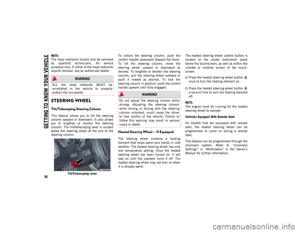
column. The tilt/telescoping lever is located
below the steering wheel at the end of the
steering column.Tilt/Telescoping Lever To unlock the steering column, push the
control handle downward (toward the floor).
To tilt the steering column, move the
steering wheel upward or downward as
desired. To lengthen or shorten the steering
column, pull the steering wheel outward or
push it inward as desired. To lock the
steering column in position, push the control
handle upward until fully engaged.
Heated Steering Wheel — If Equipped
The steering wheel contains a heating
element that helps warm your hands in cold
weather. The heated steering wheel has only
one temperature setting. Once the heated
steering wheel has been turned on, it will
stay on until the operator turns it off. The
heated steering wheel may not turn on when
it is already warm.
The heated steering wheel control button is
located on the center instrument panel
below the touchscreen, as well as within the
climate or controls screen of the touch
-
screen.
Press the heated steering wheel button
once to turn the heating element on.
Press the heated steering wheel button
a second time to turn the heating element
off.
NOTE:
The engine must be running for the heated
steering wheel to operate.
Vehicles Equipped With Remote Start
On models that are equipped with remote
start, the heated steering wheel can be
programmed to come on during a remote
start.
This feature can be programmed through the
Uconnect system. Refer to “Uconnect
Settings” in “Multimedia” in the Owner’s
Manual for further information.
WARNING!
ALL the head restraints MUST be
reinstalled in the vehicle to properly
protect the occupants.
WARNING!
Do not adjust the steering column while
driving. Adjusting the steering column
while driving or driving with the steering
column unlocked, could cause the driver
to lose control of the vehicle. Failure to
follow this warning may result in serious
injury or death.
2020_JEEP_M6_UG_UK.book Page 30
Page 33 of 328
31
EXTERIOR LIGHTS
Multifunction Lever
The multifunction lever controls the opera-
tion of the turn signals, headlight beam
selection and passing lights. The multifunc -
tion lever is located on the left side of the
steering column. Multifunction Lever
Headlight Switch
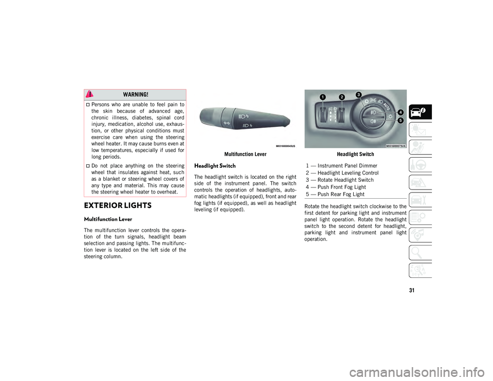
The headlight switch is located on the right
side of the instrument panel. The switch
controls the operation of headlights, auto
-
matic headlights (if equipped), front and rear
fog lights (if equipped), as well as headlight
leveling (if equipped). Headlight Switch
Rotate the headlight switch clockwise to the
first detent for parking light and instrument
panel light operation. Rotate the headlight
switch to the second detent for headlight,
parking light and instrument panel light
operation.
WARNING!
Persons who are unable to feel pain to
the skin because of advanced age,
chronic illness, diabetes, spinal cord
injury, medication, alcohol use, exhaus-
tion, or other physical conditions must
exercise care when using the steering
wheel heater. It may cause burns even at
low temperatures, especially if used for
long periods.
Do not place anything on the steering
wheel that insulates against heat, such
as a blanket or steering wheel covers of
any type and material. This may cause
the steering wheel heater to overheat.1 — Instrument Panel Dimmer
2 — Headlight Leveling Control
3 — Rotate Headlight Switch
4 — Push Front Fog Light
5 — Push Rear Fog Light
2020_JEEP_M6_UG_UK.book Page 31
Page 34 of 328
GETTING TO KNOW YOUR VEHICLE
32
Daytime Running Lights (DRL) — If
Equipped
The Daytime Running Lights will turn on
when the engine is started and remain on
unless the headlamps are turned on or the
ignition is in the OFF position.
NOTE:
If allowed by law in the country in which the
vehicle was purchased the Daytime Running
Lights can be turned on and off using the
Uconnect System. Refer to “Uconnect
Settings” in “Multimedia” in the Owner’s
Manual for further details.
High/Low Beam Switch
Push the multifunction lever toward the
instrument panel to switch the headlights to
high beams. Pulling the multifunction lever
back toward the steering wheel will return
the lights to low beams.
Automatic High Beam Headlamp Control
— If Equipped
The Automatic High Beam Headlamp Control
system provides increased forward lighting at
night by automating high beam control
through the use of a digital camera mounted
on the inside rearview mirror. This cameradetects vehicle specific light and automati
-
cally switches from high beams to low beams
until the approaching vehicle is out of view.
NOTE:
The Automatic High Beam Headlamp
Control can be turned on or off using the
Uconnect System. Refer to “Uconnect
Settings” in “Multimedia” in the Owner’s
Manual for further information.
Broken, muddy, or obstructed headlights
and taillights of vehicles in the field of
view will cause headlights to remain on
longer (closer to the vehicle). Also, dirt,
film, and other obstructions on the wind -
shield or camera lens will cause the
system to function improperly.
Flash-To-Pass
You can signal another vehicle with your
headlights by lightly pulling the multifunc -
tion lever toward you. This will cause the
high beam headlights to turn on, and remain
on, until the lever is released.
Automatic Headlights — If Equipped
This system automatically turns the head -
lights on or off according to ambient light
levels. To turn the system on, rotate the headlight switch clockwise to the last detent
for automatic headlight operation. When the
system is on, the headlight time delay
feature is also on. This means the headlights
will stay on for up to 90 seconds after you
place the ignition into the OFF position. To
turn the automatic system off, move the
headlight switch out of the AUTO position.
NOTE:
The engine must be running before the head
-
lights will come on in the automatic mode.
Headlight Time Delay
This feature provides the safety of headlight
illumination for up to 90 seconds (program -
mable) when leaving your vehicle in an unlit
area.
To activate the delay feature, place the igni -
tion in the OFF position while the headlights
are still on. Then, turn off the headlights
within 45 seconds. The delay interval begins
when the headlight switch is turned off.
If you turn the headlights or parking lights
on, or place the ignition in ACC or RUN, the
system will cancel the delay.
If you turn the headlights off before the igni -
tion, they will turn off in the normal manner.
2020_JEEP_M6_UG_UK.book Page 32
Page 36 of 328
GETTING TO KNOW YOUR VEHICLE
34
NOTE:
If either light remains on and does not
flash, or there is a very fast flash rate,
check for a defective outside light bulb. If
an indicator fails to light when the lever is
moved, it would suggest that the indicator
bulb is defective.
A “Turn Signal On” message will appear in
the instrument cluster display and a
continuous chime will sound if the vehicle
is driven more than 1 mile (1.6 km) witheither turn signal on.
When the Daytime Running Lights are on
and a turn signal is activated, the Daytime
Running Lamp will turn off on the side of
the vehicle in which the turn signal is
flashing. The Daytime Running Lamp will
turn back on when the turn signal is
turned off.
Headlight Leveling System — If Equipped
This system allows the driver to maintain
proper headlight beam position with the road
surface regardless of vehicle load.
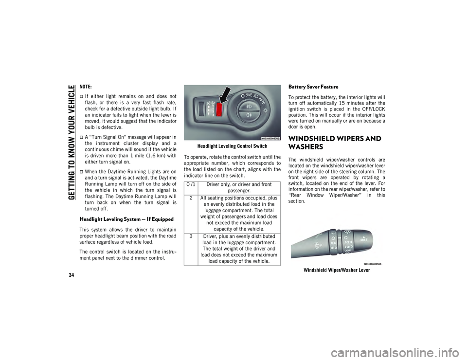
The control switch is located on the instru -
ment panel next to the dimmer control. Headlight Leveling Control Switch
To operate, rotate the control switch until the
appropriate number, which corresponds to
the load listed on the chart, aligns with the
indicator line on the switch.
Battery Saver Feature
To protect the battery, the interior lights will
turn off automatically 15 minutes after the
ignition switch is placed in the OFF/LOCK
position. This will occur if the interior lights
were turned on manually or are on because a
door is open.
WINDSHIELD WIPERS AND
WASHERS
The windshield wiper/washer controls are
located on the windshield wiper/washer lever
on the right side of the steering column. The
front wipers are operated by rotating a
switch, located on the end of the lever. For
information on the rear wiper/washer, refer to
“Rear Window Wiper/Washer” in this
section.
Windshield Wiper/Washer Lever
0 /1 Driver only, or driver and front
passenger.
2 All seating positions occupied, plus an evenly distributed load in the luggage compartment. The total
weight of passengers and load does not exceed the maximum load capacity of the vehicle.
3 Driver, plus an evenly distributed load in the luggage compartment. The total weight of the driver and
load does not exceed the maximum load capacity of the vehicle.
2020_JEEP_M6_UG_UK.book Page 34
Page 43 of 328
41
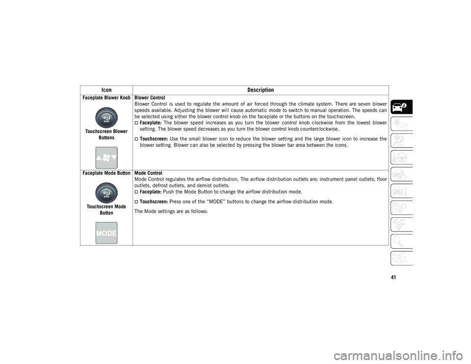
Faceplate Blower KnobTouchscreen Blower Buttons Blower Control
Blower Control is used to regulate the amount of air forced through the climate system. There are seven blower
speeds available. Adjusting the blower will cause automatic mode to switch to manual operation. The speeds can
be selected using either the blower control knob on the faceplate or the buttons on the touchscreen.
Faceplate:
The blower speed increases as you turn the blower control knob clockwise from the lowest blower
setting. The blower speed decreases as you turn the blower control knob counterclockwise.
Touchscreen: Use the small blower icon to reduce the blower setting and the large blower icon to increase the
blower setting. Blower can also be selected by pressing the blower bar area between the icons.
Faceplate Mode Button
Touchscreen Mode Button Mode Control
Mode Control regulates the airflow distribution. The airflow distribution outlets are: instrument panel outlets, floor
outlets, defrost outlets, and demist outlets.
Faceplate:
Push the Mode Button to change the airflow distribution mode.
Touchscreen: Press one of the “MODE” buttons to change the airflow distribution mode.
The Mode settings are as follows:
Icon Description
2020_JEEP_M6_UG_UK.book Page 41
Page 48 of 328
GETTING TO KNOW YOUR VEHICLE
46
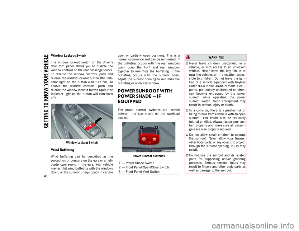
Window Lockout Switch
The window lockout switch on the driver's
door trim panel allows you to disable the
window controls on the rear passenger doors.
To disable the window controls, push and
release the window lockout button (the indi-
cator light on the button with turn on). To
enable the window controls, push and
release the window lockout button again (the
indicator light on the button will turn back
off).
Window Lockout Switch
Wind Buffeting
Wind buffeting can be described as the
perception of pressure on the ears or a heli -
copter-type sound in the ears. Your vehicle
may exhibit wind buffeting with the windows
down, or the sunroof (if equipped) in certain open or partially open positions. This is a
normal occurrence and can be minimized. If
the buffeting occurs with the rear windows
open, open the front and rear windows
together to minimize the buffeting. If the
buffeting occurs with the sunroof open,
adjust the sunroof opening to minimize the
buffeting or open any window.
POWER SUNROOF WITH
POWER SHADE — IF
EQUIPPED
The power sunroof switches are located
between the sun visors on the overhead
console.
Power Sunroof Switches
1 — Power Shade Switch
2 — Front Panel Open/Close Switch
3 — Front Panel Vent Switch
WARNING!
Never leave children unattended in a
vehicle, or with access to an unlocked
vehicle. Never leave the key fob in or
near the vehicle, or in a location acces-
sible to children. Do not leave the igni -
tion of a vehicle equipped with Keyless
Enter-N-Go in the ON/RUN mode. Occu -
pants, particularly unattended children,
can become entrapped by the power
sunroof while operating the power
sunroof switch. Such entrapment may
result in serious injury or death.
In a collision, there is a greater risk of
being thrown from a vehicle with an open
sunroof. You could also be seriously
injured or killed. Always fasten your seat
belt properly and make sure all passen -
gers are also properly secured.
Do not allow small children to operate
the sunroof. Never allow your fingers,
other body parts, or any object, to project
through the sunroof opening. Injury may
result.
Do not use the sunroof and its related
parts for supporting and/or grabbing
purposes. Serious personal injury may
result to fingers and other body parts as
well as damage to the sunroof.
2020_JEEP_M6_UG_UK.book Page 46
Page 51 of 328
49
HOOD
Opening The Hood
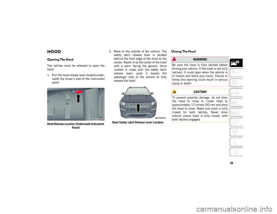
Two latches must be released to open the
hood.
1. Pull the hood release lever located under-
neath the driver’s side of the instrument
panel.
Hood Release Location (Underneath Instrument Panel) 2. Move to the outside of the vehicle. The
safety latch release lever is located
behind the front edge of the hood at the
center. Reach in at the center of the hood
with a palm facing the ground. Once
contact is made with the safety latch
release lever, push it toward the
passenger side of the vehicle to fully
release the hood.
Hood Safety Latch Release Lever Location
Closing The Hood
WARNING!
Be sure the hood is fully latched before
driving your vehicle. If the hood is not fully
latched, it could open when the vehicle is
in motion and block your vision. Failure to
follow this warning could result in serious
injury or death.
CAUTION!
To prevent possible damage, do not slam
the hood to close it. Lower hood to
approximately 12 inches (30 cm) and drop
the hood to close. Make sure hood is fully
closed for both latches. Never drive
vehicle unless hood is fully closed, with
both latches engaged.
2020_JEEP_M6_UG_UK.book Page 49
Page 52 of 328
GETTING TO KNOW YOUR VEHICLE
50
LIFTGATE
Opening
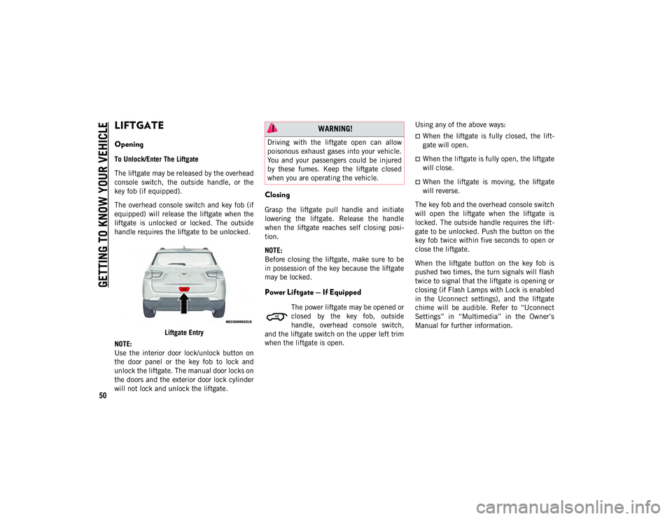
To Unlock/Enter The Liftgate
The liftgate may be released by the overhead
console switch, the outside handle, or the
key fob (if equipped).
The overhead console switch and key fob (if
equipped) will release the liftgate when the
liftgate is unlocked or locked. The outside
handle requires the liftgate to be unlocked.Liftgate Entry
NOTE:
Use the interior door lock/unlock button on
the door panel or the key fob to lock and
unlock the liftgate. The manual door locks on
the doors and the exterior door lock cylinder
will not lock and unlock the liftgate.
Closing
Grasp the liftgate pull handle and initiate
lowering the liftgate. Release the handle
when the liftgate reaches self closing posi -
tion.
NOTE:
Before closing the liftgate, make sure to be
in possession of the key because the liftgate
may be locked.
Power Liftgate — If Equipped
The power liftgate may be opened or
closed by the key fob, outside
handle, overhead console switch,
and the liftgate switch on the upper left trim
when the liftgate is open. Using any of the above ways:
When the liftgate is fully closed, the lift
-
gate will open.
When the liftgate is fully open, the liftgate
will close.
When the liftgate is moving, the liftgate
will reverse.
The key fob and the overhead console switch
will open the liftgate when the liftgate is
locked. The outside handle requires the lift -
gate to be unlocked. Push the button on the
key fob twice within five seconds to open or
close the liftgate.
When the liftgate button on the key fob is
pushed two times, the turn signals will flash
twice to signal that the liftgate is opening or
closing (if Flash Lamps with Lock is enabled
in the Uconnect settings), and the liftgate
chime will be audible. Refer to “Uconnect
Settings” in “Multimedia” in the Owner’s
Manual for further information.
WARNING!
Driving with the liftgate open can allow
poisonous exhaust gases into your vehicle.
You and your passengers could be injured
by these fumes. Keep the liftgate closed
when you are operating the vehicle.
2020_JEEP_M6_UG_UK.book Page 50
Page 53 of 328
51
(Continued)
NOTE:
Before closing the liftgate, make sure to
be in possession of the key because the
liftgate may be locked.
Use the interior door lock/unlock button
on the door panel or the key fob to lock
and unlock the liftgate. The manual door
locks on the doors and the exterior door
lock cylinder will not lock and unlock the
liftgate.
Lock The Vehicle
NOTE:
The liftgate will not power open or close if
the gear selector is in gear or the vehicle
speed is above 0 mph (0 km/h).
If anything obstructs the power liftgate
while it is closing or opening, the liftgate
will automatically reverse to the closed or
open position, provided it meets sufficient
resistance.
There are pinch sensors attached to the
side of the liftgate opening. Light pressure
anywhere along these strips will cause the
liftgate to return to the open position.
If the power liftgate encounters multiple
obstructions within the same cycle, the
system will automatically stop. If this
occurs, the liftgate must be opened or
closed manually.
The power liftgate will not operate in
temperatures below −22°F (−30°C) or
temperatures above 150°F (65°C). Be
sure to remove any buildup of snow or ice
from the liftgate before pushing any of the
power liftgate switches.
If the liftgate is left open for an extended
period of time, the liftgate may need to be
closed manually to reset power liftgate
functionality.
Gas props support the liftgate in the open
position. However, because the gas pres-
sure drops with temperature, it may be
necessary to assist the props when
opening the liftgate in cold weather.
Before driving off, check the instrument
cluster for a liftgate or door open message
or warning indicator. Failure to do this
could result in unintentionally leaving the
liftgate open while driving.
If your liftgate is power closing and you
put the vehicle in gear, the liftgate will
continue to power close. However, vehicle
movement may result in a detection of an
obstruction.
If the electronic liftgate release handle is
pushed while the power liftgate is
opening, the liftgate motor will disengage
to allow manual operation.
If the electronic liftgate release handle is
pushed while the power liftgate is closing,
the liftgate will reverse to the full open
position.
WARNING!
During power operation, personal injury or
cargo damage may occur. Ensure the
liftgate travel path is clear. Make sure the
liftgate is closed and latched before
driving away.
WARNING!
Driving with the liftgate open can allow
poisonous exhaust gases into your
vehicle. You and your passengers could
be injured by these fumes. Keep the lift -
gate closed when you are operating the
vehicle.
2020_JEEP_M6_UG_UK.book Page 51
Page 61 of 328
59
TRIP COMPUTER
Push and release the up or down arrow
button until the Trip A or Trip B icon is high-
lighted in the instrument cluster display
(Toggle left or right to select Trip A or Trip B).
Push and release the OK button to display
the Trip information.
WARNING LIGHTS AND
MESSAGES
The warning/indicator lights will illuminate
in the instrument panel together with a dedi -
cated message and/or acoustic signal when
applicable. These indications are indicative
and precautionary and as such must not be
considered as exhaustive and/or alternative to the information contained in the Owner’s
Manual, which you are advised to read care
-
fully in all cases. Always refer to the informa -
tion in this chapter in the event of a failure
indication. All active telltales will display
first if applicable. The system check menu
may appear different based upon equipment
options and current vehicle status. Some
telltales are optional and may not appear.
Red Warning Lights
Air Bag Warning Light
This warning light will illuminate to
indicate a fault with the air bag, and
will turn on for four to eight seconds
as a bulb check when the ignition is placed
in the ON/RUN or ACC/ON/RUN position. This light will illuminate with a single chime
when a fault with the air bag has been
detected, it will stay on until the fault is
cleared. If the light is either not on during
startup, stays on, or turns on while driving,
have the system inspected at an authorized
dealer as soon as possible.
Brake Warning Light
This warning light monitors various
brake functions, including brake
fluid level and parking brake appli
-
cation. If the brake light turns on it may indi -
cate that the parking brake is applied, that
the brake fluid level is low, or that there is a
problem with the anti-lock brake system.
Engine Will Not Start Service
AdBlue® System See Dealer
NOTE:
The display may take up to five seconds to update after adding 2 gallons (7.5 Liters) or more of
AdBlue® (UREA) to the AdBlue® (UREA) tank. If you have a fault related to the AdBlue® (UREA)
system, the display may not update to the new level. See an authorized dealer for service.
AdBlue® freezes at temperatures lower than 12°F (-11°C). If the car stands for a long time at this
temperature, refilling could be difficult. For this reason, it is advised to park the vehicle in a garage
and/or heated environment, and wait for the AdBlue® (UREA) to return to liquid state before topping
up.
MESSAGE
DESCRIPTION
2020_JEEP_M6_UG_UK.book Page 59