power steering JEEP COMPASS 2020 Owner handbook (in English)
[x] Cancel search | Manufacturer: JEEP, Model Year: 2020, Model line: COMPASS, Model: JEEP COMPASS 2020Pages: 328, PDF Size: 8.85 MB
Page 17 of 328
15
(Continued)
(side opposite of the emergency key) of the
key fob against the START/STOP ignition
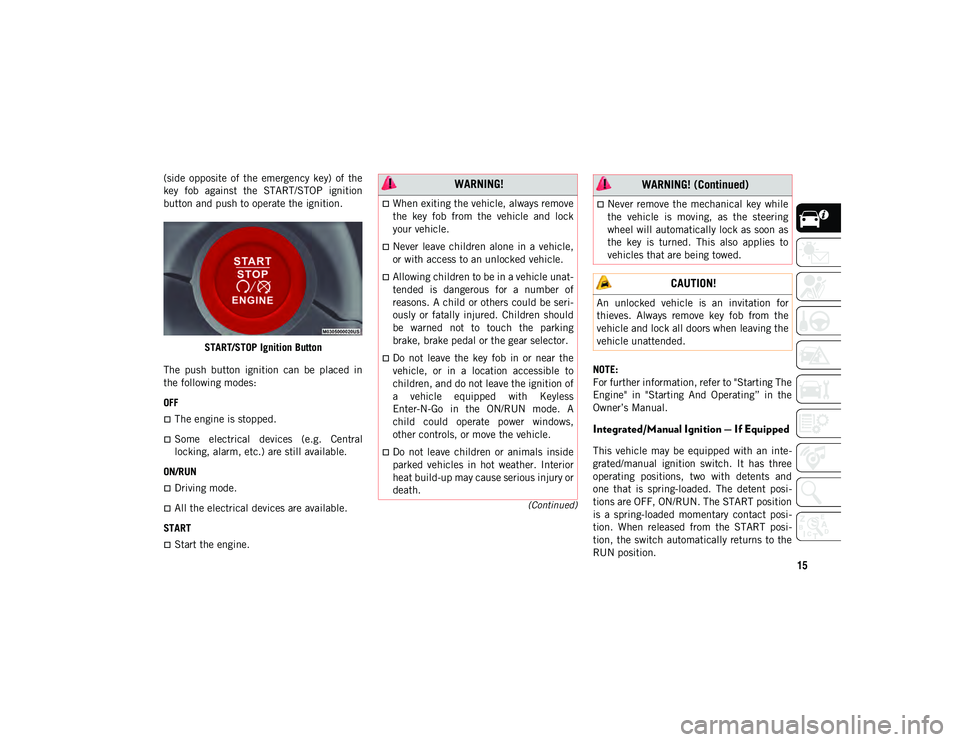
button and push to operate the ignition.START/STOP Ignition Button
The push button ignition can be placed in
the following modes:
OFF
The engine is stopped.
Some electrical devices (e.g. Central
locking, alarm, etc.) are still available.
ON/RUN
Driving mode.
All the electrical devices are available.
START
Start the engine. NOTE:
For further information, refer to "Starting The
Engine" in "Starting And Operating” in the
Owner’s Manual.
Integrated/Manual Ignition — If Equipped
This vehicle may be equipped with an inte
-
grated/manual ignition switch. It has three
operating positions, two with detents and
one that is spring-loaded. The detent posi -
tions are OFF, ON/RUN. The START position
is a spring-loaded momentary contact posi -
tion. When released from the START posi -
tion, the switch automatically returns to the
RUN position.
WARNING!
When exiting the vehicle, always remove
the key fob from the vehicle and lock
your vehicle.
Never leave children alone in a vehicle,
or with access to an unlocked vehicle.
Allowing children to be in a vehicle unat -
tended is dangerous for a number of
reasons. A child or others could be seri -
ously or fatally injured. Children should
be warned not to touch the parking
brake, brake pedal or the gear selector.
Do not leave the key fob in or near the
vehicle, or in a location accessible to
children, and do not leave the ignition of
a vehicle equipped with Keyless
Enter-N-Go in the ON/RUN mode. A
child could operate power windows,
other controls, or move the vehicle.
Do not leave children or animals inside
parked vehicles in hot weather. Interior
heat build-up may cause serious injury or
death.
Never remove the mechanical key while
the vehicle is moving, as the steering
wheel will automatically lock as soon as
the key is turned. This also applies to
vehicles that are being towed.
CAUTION!
An unlocked vehicle is an invitation for
thieves. Always remove key fob from the
vehicle and lock all doors when leaving the
vehicle unattended.
WARNING! (Continued)
2020_JEEP_M6_UG_UK.book Page 15
Page 18 of 328
GETTING TO KNOW YOUR VEHICLE
16
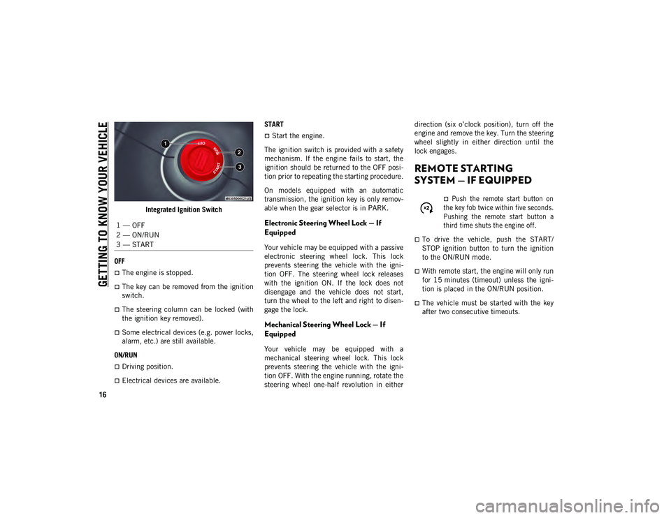
Integrated Ignition Switch
OFF
The engine is stopped.
The key can be removed from the ignition
switch.
The steering column can be locked (with
the ignition key removed).
Some electrical devices (e.g. power locks,
alarm, etc.) are still available.
ON/RUN
Driving position.
Electrical devices are available. START
Start the engine.
The ignition switch is provided with a safety
mechanism. If the engine fails to start, the
ignition should be returned to the OFF posi -
tion prior to repeating the starting procedure.
On models equipped with an automatic
transmission, the ignition key is only remov -
able when the gear selector is in PARK.
Electronic Steering Wheel Lock — If
Equipped
Your vehicle may be equipped with a passive
electronic steering wheel lock. This lock
prevents steering the vehicle with the igni -
tion OFF. The steering wheel lock releases
with the ignition ON. If the lock does not
disengage and the vehicle does not start,
turn the wheel to the left and right to disen -
gage the lock.
Mechanical Steering Wheel Lock — If
Equipped
Your vehicle may be equipped with a
mechanical steering wheel lock. This lock
prevents steering the vehicle with the igni -
tion OFF. With the engine running, rotate the
steering wheel one-half revolution in either direction (six o’clock position), turn off the
engine and remove the key. Turn the steering
wheel slightly in either direction until the
lock engages.
REMOTE STARTING
SYSTEM — IF EQUIPPED
Push the remote start button on
the key fob twice within five seconds.
Pushing the remote start button a
third time shuts the engine off.
To drive the vehicle, push the START/
STOP ignition button to turn the ignition
to the ON/RUN mode.
With remote start, the engine will only run
for 15 minutes (timeout) unless the igni -
tion is placed in the ON/RUN position.
The vehicle must be started with the key
after two consecutive timeouts.
1 — OFF
2 — ON/RUN
3 — START
2020_JEEP_M6_UG_UK.book Page 16
Page 63 of 328
61
Electric Power Steering Fault Warning Light
This warning light will turn on when
there's a fault with the EPS (Electric
Power Steering) system. Refer to
“Power Steering” in “Starting And
Operating” in the Owner’s Manual for further
information.
Electronic Throttle Control (ETC) Warning
Light
This warning light will illuminate to
indicate a problem with the Elec -
tronic Throttle Control (ETC)
system. If a problem is detected
while the vehicle is running, the light will
either stay on or flash depending on the
nature of the problem. Cycle the ignition
when the vehicle is safely and completely
stopped and the transmission is placed in
the PARK position. The light should turn off.
If the light remains on with the vehicle
running, your vehicle will usually be drivable;
however, see an authorized dealer for service
as soon as possible. NOTE:
This light may turn on if the accelerator and
brake pedals are pressed at the same time.
If the light continues to flash when the
vehicle is running, immediate service is
required and you may experience reduced
performance, an elevated/rough idle, or
engine stall and your vehicle may require
towing. The light will come on when the igni
-
tion is placed in the ON/RUN or ACC/ON/
RUN position and remain on briefly as a bulb
check. If the light does not come on during
starting, have the system checked by an
authorized dealer.
Engine Temperature Warning Light
This warning light will illuminate to
warn of an overheated engine condi -
tion. If the engine coolant tempera -
ture is too high, this light will illuminate and
a single chime will sound.
If the light turns on while driving, safely pull
over and stop the vehicle. If the A/C system
is on, turn it off. Also, shift the transmission
into NEUTRAL and idle the vehicle. If the
temperature reading does not return to
normal, turn the engine off immediately and
call for service. Refer to “If Your Engine Overheats” in “In
Case Of Emergency” for further information.
Hood Open Warning Light
This warning light will illuminate
when the hood is left open and not
fully closed.
NOTE:
If the vehicle is moving, there will also be a
single chime.
Liftgate Open Warning Light
This warning light will illuminate
when the liftgate is open.
NOTE:
If the vehicle is moving, there will also be a
single chime.
Oil Pressure Warning Light
This warning light will illuminate to
indicate low engine oil pressure. If
the light turns on while driving, stop
the vehicle, shut off the engine as soon as
possible, and contact an authorized dealer. A
chime will sound when this light turns on.
Do not operate the vehicle until the cause is
corrected. This light does not indicate how
WARNING!
Continued operation with reduced assist
could pose a safety risk to yourself and
others. Service should be obtained as soon
as possible.
2020_JEEP_M6_UG_UK.book Page 61
Page 75 of 328
73
If the “Anti-Lock Brake Warning Light” is on,
the brake system should be serviced as soon
as possible to restore the benefits of
anti-lock brakes. If the “Anti-Lock Brake
Warning Light” does not come on when the
ignition is turned to the ON/RUN mode, have
the light repaired as soon as possible.
Electronic Brake Control System
Your vehicle is equipped with an advanced
Electronic Brake Control system (EBC). This
system includes Electronic Brake Force
Distribution (EBD), Anti-Lock Brake System
(ABS), Brake Assist System (BAS), Hill Start
Assist (HSA), Traction Control System (TCS),
Electronic Stability Control (ESC), and Elec-
tronic Roll Mitigation (ERM). These systems
work together to enhance both vehicle
stability and control in various driving condi -
tions.
Your vehicle may also be equipped with
Ready Alert Braking (RAB), Rain Brake
Support (RBS), Trailer Sway Control (TSC),
Hill Descent Control (HDC), and Dynamic
Steering Torque (DST).
Brake Assist System (BAS) — If Equipped
The Brake Assist System (BAS) is designed
to optimize the vehicle’s braking capability during emergency braking maneuvers. The
system detects an emergency braking situa
-
tion by sensing the rate and amount of brake
application and then applies optimum pres -
sure to the brakes. This can help reduce
braking distances. The BAS complements
the Anti-Lock Brake System (ABS). Applying
the brakes very quickly results in the best
BAS assistance. To receive the benefit of the
system, you must apply continuous braking
pressure during the stopping sequence, (do
not “pump” the brakes). Do not reduce brake
pedal pressure unless braking is no longer
desired. Once the brake pedal is released,
the BAS is deactivated.
Brake System Warning Light
The red “Brake System Warning Light” will
turn on when the ignition is turned to the ON/
RUN mode and may stay on for as long as
four seconds.
If the “Brake System Warning Light”
remains on or comes on while driving, it indi -
cates that the brake system is not func -
tioning properly and that immediate service
is required. If the “Brake System Warning
Light” does not come on when the ignition is
turned to the ON/RUN mode, have the light
repaired as soon as possible.
Dynamic Steering Torque (DST)
Dynamic Steering Torque (DST) is a feature
of the ESC and Electric Power Steering
(EPS) modules that provides torque at the
steering wheel for certain driving conditions
in which the ESC module is detecting vehicle
instability. The torque that the steering
wheel receives is only meant to help the
driver realize optimal steering behavior in
order to reach/maintain vehicle stability. The
only notification the driver receives that the
feature is active is the torque applied to the
steering wheel. WARNING!
The Brake Assist System (BAS) cannot
prevent the natural laws of physics from
acting on the vehicle, nor can it increase
the traction afforded by prevailing road
conditions. BAS cannot prevent collisions,
including those resulting from excessive
speed in turns, driving on very slippery
surfaces, or hydroplaning. The capabilities
of a BAS-equipped vehicle must never be
exploited in a reckless or dangerous
manner, which could jeopardize the user's
safety or the safety of others.
2020_JEEP_M6_UG_UK.book Page 73
Page 76 of 328
SAFETY
74
NOTE:
The DST feature is only meant to help the
driver realize the correct course of action
through small torques on the steering wheel,
which means the effectiveness of the DST
feature is highly dependent on the driver’s
sensitivity and overall reaction to the applied
torque. It is very important to realize that this
feature will not steer the vehicle, meaning
the driver is still responsible for steering the
vehicle.
Electronic Brake Force Distribution (EBD)
This function manages the distribution of the
braking torque between the front and rear
axles by limiting braking pressure to the rear
axle. This is done to prevent overslip of the
rear wheels to avoid vehicle instability, and
to prevent the rear axle from entering ABS
before the front axle.
Electronic Roll Mitigation (ERM)
Electronic Roll Mitigation (ERM) anticipates
the potential for wheel lift by monitoring the
driver’s steering wheel input and the speed
of the vehicle. When ERM determines that
the rate of change of the steering wheel
angle and vehicle’s speed are sufficient to
potentially cause wheel lift, it then appliesthe appropriate brake and may also reduce
engine power to lessen the chance that
wheel lift will occur. ERM can only reduce
the chance of wheel lift occurring during
severe or evasive driving maneuvers; it
cannot prevent wheel lift due to other
factors, such as road conditions, leaving the
roadway, or striking objects or other vehicles.Electronic Stability Control (ESC)
Electronic Stability Control (ESC) enhances
directional control and stability of the
vehicle under various driving conditions.
ESC corrects for oversteering or under
-
steering of the vehicle by applying the brake
of the appropriate wheel(s) to assist in coun -teracting the oversteer or understeer condi
-
tion. Engine power may also be reduced to
help the vehicle maintain the desired path.
ESC uses sensors in the vehicle to determine
the vehicle path intended by the driver and
compares it to the actual path of the vehicle.
When the actual path does not match the
intended path, ESC applies the brake of the
appropriate wheel to assist in counteracting
the oversteer or understeer condition.
Oversteer — when the vehicle is turning
more than appropriate for the steering
wheel position.
Understeer — when the vehicle is turning
less than appropriate for the steering
wheel position.
The “ESC Activation/Malfunction Indicator
Light” located in the instrument cluster will
start to flash as soon as the ESC system
becomes active. The “ESC Activation/
Malfunction Indicator Light” also flashes
when the TCS is active. If the “ESC Activa -
tion/Malfunction Indicator Light” begins to
flash during acceleration, ease up on the
accelerator and apply as little throttle as
possible. Be sure to adapt your speed and
driving to the prevailing road conditions.
WARNING!
Many factors, such as vehicle loading,
road conditions and driving conditions,
influence the chance that wheel lift or
rollover may occur. ERM cannot prevent all
wheel lift or roll overs, especially those
that involve leaving the roadway or striking
objects or other vehicles. The capabilities
of an ERM-equipped vehicle must never
be exploited in a reckless or dangerous
manner which could jeopardize the user's
safety or the safety of others.
2020_JEEP_M6_UG_UK.book Page 74
Page 100 of 328
SAFETY
98
Seat Belt Pretensioner
The front and second row outboard seat belt
systems are equipped with pretensioning
devices that are designed to remove slack
from the seat belt in the event of a collision.
These devices may improve the performance
of the seat belt by removing slack from the
seat belt early in a collision. Pretensioners
work for all size occupants, including those
in child restraints.
NOTE:
These devices are not a substitute for proper
seat belt placement by the occupant. The
seat belt still must be worn snugly and posi-
tioned properly.
The pretensioners are triggered by the Occu -
pant Restraint Controller (ORC). Like the air
bags, the pretensioners are single use items.
A deployed pretensioner or a deployed air
bag must be replaced immediately.
Energy Management Feature — If Equipped
The front outboard seat belt system is
equipped and the second row outboard seat
belt system may be equipped with an Energy
Management feature that may help further
reduce the risk of injury in the event of a collision. The seat belt system has a retractor
assembly that is designed to release webbing
in a controlled manner.
Supplemental Restraint Systems (SRS)
Some of the safety features described in this
section may be standard equipment on some
models, or may be optional equipment on
others. If you are not sure, ask an authorized
dealer.
The air bag system must be ready to protect
you in a collision. The Occupant Restraint
Controller (ORC) monitors the internal
circuits and interconnecting wiring associ
-
ated with the electrical Air Bag System
Components. Your vehicle may be equipped
with the following Air Bag System Compo -
nents:
Air Bag System Components
Occupant Restraint Controller (ORC)
Air Bag Warning Light
Steering Wheel and Column
Instrument Panel
Knee Impact Bolsters
Driver and Front Passenger Air Bags
Seat Belt Buckle Switch
Supplemental Side Air Bags
Front and Side Impact Sensors
Seat Belt Pretensioners
Seat Track Position Sensors
Air Bag Warning Light
The Occupant Restraint Controller (ORC)
monitors the readiness of the electronic
parts of the air bag system whenever the igni -
tion switch is in the START or ON/RUN posi -
tion. If the ignition switch is in the OFF
position or in the ACC position, the air bag
system is not on and the air bags will not
inflate.
The ORC contains a backup power supply
system that may deploy the air bag system
even if the battery loses power or it becomes
disconnected prior to deployment.
The ORC turns on the Air Bag Warning Light
in the instrument panel for approximately
four to eight seconds for a self-check when
the ignition switch is first in the ON/RUN
position. After the self-check, the Air Bag
Warning Light will turn off. If the ORC
detects a malfunction in any part of the
2020_JEEP_M6_UG_UK.book Page 98
Page 113 of 328
111
NOTE:
Air bag covers may not be obvious in the
interior trim, but they will open during air
bag deployment.
After any collision, the vehicle should be
taken to an authorized dealer immedi-
ately.
Enhanced Accident Response System
In the event of an impact, if the communica -
tion network remains intact, and the power
remains intact, depending on the nature of
the event, the ORC will determine whether to
have the Enhanced Accident Response
System perform the following functions:
Cut off fuel to the engine (If Equipped)
Cut off battery power to the electric motor
(If Equipped)
Flash hazard lights as long as the battery
has power
Turn on the interior lights, which remain
on as long as the battery has power or for
15 minutes from the intervention of the
Enhanced Accident Response System.
Unlock the power door locks. Your vehicle may also be designed to perform
any of these other functions in response to
the Enhanced Accident Response System:
Turn off the Fuel Filter Heater, turn off the
HVAC Blower Motor, close the HVAC
Circulation Door
Cut off battery power to the:
Engine
Electric motor (if equipped)
Electric power steering
Brake booster
Electric park brake
Automatic transmission gear selector
Horn
Front wiper
Headlamp washer pump
NOTE:
After an accident, remember to place the
ignition to the STOP (OFF/LOCK) position
and remove the key from the ignition switch
to avoid draining the battery. Carefully check
the vehicle for fuel leaks in the engine
compartment and on the ground near the
engine compartment and fuel tank before resetting the system and starting the engine.
If there are no fuel leaks or damage to the
vehicle electrical devices (e.g. headlights)
after an accident, reset the system by
following the procedure described below. If
you have any doubt, contact an authorized
dealer.
Enhanced Accident Response System Reset
Procedure
After the event occurs, when the system is
active, a message regarding fuel cutoff is
displayed. Turn the ignition switch from igni
-
tion AVV/START or MAR/ACC/ON/RUN to
ignition STOP/OFF/LOCK. Carefully check
the vehicle for fuel leaks in the engine
compartment and on the ground near the
engine compartment and fuel tank before
resetting the system and starting the engine.
Depending on the nature of the event the left
and right turn signal lights, located in the
instrument panel, may both be blinking and
will continue to blink. In order to move your
vehicle to the side of the road, you must
follow the system reset procedure.
2020_JEEP_M6_UG_UK.book Page 111
Page 174 of 328
STARTING AND OPERATING
172
Tongue Weight (TW)
The tongue weight is the downward force
exerted on the hitch ball by the trailer. You
must consider this as part of the load on your
vehicle.
Trailer Frontal Area
The frontal area is the maximum height
multiplied by the maximum width of the
front of a trailer.
Trailer Sway Control
The trailer sway control can be a mechanical
telescoping link that can be installed
between the hitch receiver and the trailer
tongue that typically provides adjustable fric-
tion associated with the telescoping motion
to dampen any unwanted trailer swaying
motions while traveling.
If equipped, the electronic Trailer Sway
Control (TSC) recognizes a swaying trailer
and automatically applies individual wheel
brakes and/or reduces engine power to
attempt to eliminate the trailer sway.
Weight-Carrying Hitch
A weight-carrying hitch supports the trailer
tongue weight, just as if it were luggage
located at a hitch ball or some other
connecting point of the vehicle. These kinds
of hitches are the most popular on the
market today and they are commonly used to
tow small and medium sized trailers.
Weight-Distributing Hitch
A weight-distributing system works by
applying leverage through spring (load) bars.
They are typically used for heavier loads to
distribute trailer tongue weight to the tow
vehicle's front axle and the trailer axle(s).
When used in accordance with the manufac -
turer's directions, it provides for a more level
ride, offering more consistent steering and
brake control thereby enhancing towing
safety. The addition of a friction/hydraulic
sway control also dampens sway caused by
traffic and crosswinds and contributes posi -
tively to tow vehicle and trailer stability. Trailer sway control and a weight distributing
(load equalizing) hitch are recommended for
heavier Tongue Weights (TW) and may be
required depending on vehicle and trailer
configuration/loading to comply with Gross
Axle Weight Rating (GAWR) requirements.
WARNING!
An improperly adjusted Weight Distrib
-
uting Hitch system may reduce
handling, stability, braking performance,
and could result in a collision.
Weight Distributing Systems may not be
compatible with Surge Brake Couplers.
Consult with your hitch and trailer manu -
facturer or a reputable Recreational
Vehicle dealer for additional informa-
tion.
2020_JEEP_M6_UG_UK.book Page 172
Page 184 of 328
IN CASE OF EMERGENCY
182
FUSES
General Information
The fuses protect electrical systems against
excessive current.
When a device does not work, you must
check the fuse element inside the blade fuse
for a break/melt.
Also, please be aware that when using power
outlets for extended periods of time with the
engine off may result in vehicle battery
discharge.
Fuse Location
The fuses are grouped into controllers
located in the engine compartment.
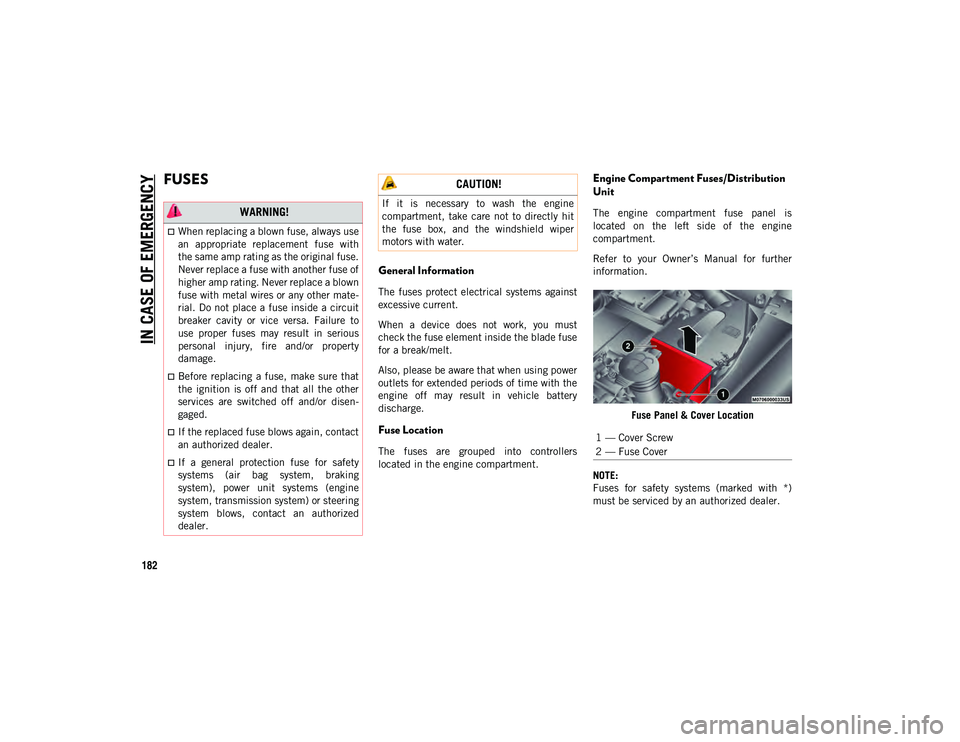
Engine Compartment Fuses/Distribution
Unit
The engine compartment fuse panel is
located on the left side of the engine
compartment.
Refer to your Owner’s Manual for further
information.Fuse Panel & Cover Location
NOTE:
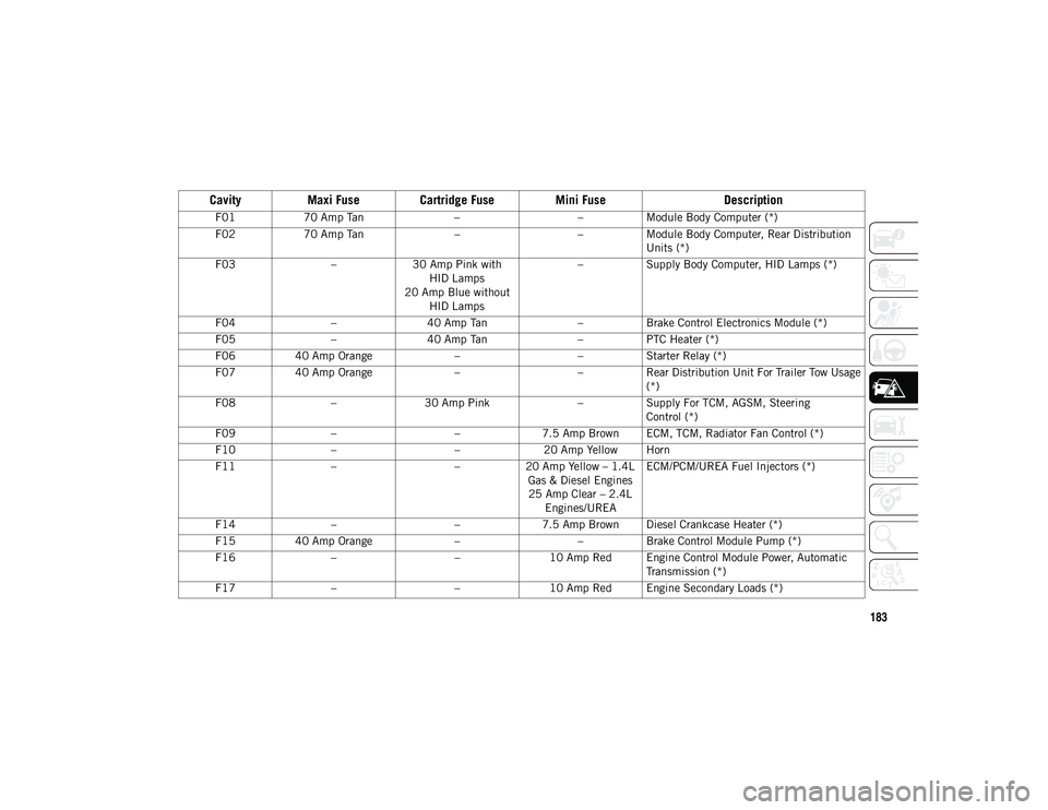
Fuses for safety systems (marked with *)
must be serviced by an authorized dealer. WARNING!
When replacing a blown fuse, always use
an appropriate replacement fuse with
the same amp rating as the original fuse.
Never replace a fuse with another fuse of
higher amp rating. Never replace a blown
fuse with metal wires or any other mate-
rial. Do not place a fuse inside a circuit
breaker cavity or vice versa. Failure to
use proper fuses may result in serious
personal injury, fire and/or property
damage.
Before replacing a fuse, make sure that
the ignition is off and that all the other
services are switched off and/or disen -
gaged.
If the replaced fuse blows again, contact
an authorized dealer.
If a general protection fuse for safety
systems (air bag system, braking
system), power unit systems (engine
system, transmission system) or steering
system blows, contact an authorized
dealer.
CAUTION!
If it is necessary to wash the engine
compartment, take care not to directly hit
the fuse box, and the windshield wiper
motors with water.
1 — Cover Screw
2 — Fuse Cover
2020_JEEP_M6_UG_UK.book Page 182
Page 185 of 328
183
Cavity
Maxi Fuse Cartridge Fuse Mini Fuse Description
F0170 Amp Tan ––Module Body Computer (*)
F02 70 Amp Tan ––Module Body Computer, Rear Distribution
Units (*)
F03 –30 Amp Pink with
HID Lamps
20 Amp Blue without HID Lamps –
Supply Body Computer, HID Lamps (*)
F04 –40 Amp Tan –Brake Control Electronics Module (*)
F05 –40 Amp Tan –PTC Heater (*)
F06 40 Amp Orange ––Starter Relay (*)
F07 40 Amp Orange ––Rear Distribution Unit For Trailer Tow Usage
(*)
F08 –30 Amp Pink –Supply For TCM, AGSM, Steering
Control (*)
F09 – –7.5 Amp Brown ECM, TCM, Radiator Fan Control (*)
F10 – –20 Amp Yellow Horn
F11 – –20 Amp Yellow – 1.4L
Gas & Diesel Engines25 Amp Clear – 2.4L Engines/UREA ECM/PCM/UREA Fuel Injectors (*)
F14 – –7.5 Amp Brown Diesel Crankcase Heater (*)
F15 40 Amp Orange ––Brake Control Module Pump (*)
F16 – –10 Amp Red Engine Control Module Power, Automatic
Transmission (*)
F17 – –10 Amp Red Engine Secondary Loads (*)
2020_JEEP_M6_UG_UK.book Page 183