clock JEEP GLADIATOR 2023 User Guide
[x] Cancel search | Manufacturer: JEEP, Model Year: 2023, Model line: GLADIATOR, Model: JEEP GLADIATOR 2023Pages: 448, PDF Size: 17.37 MB
Page 195 of 448
STARTING AND OPERATING193
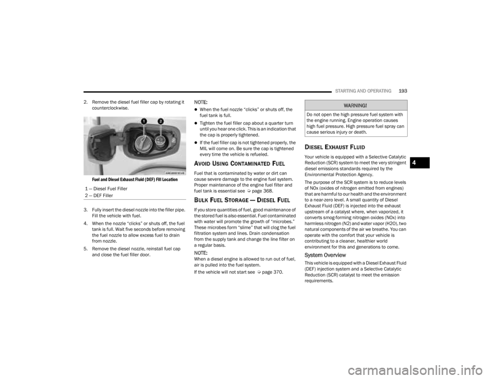
2. Remove the diesel fuel filler cap by rotating it counterclockwise.
Fuel and Diesel Exhaust Fluid (DEF) Fill Location
3. Fully insert the diesel nozzle into the filler pipe. Fill the vehicle with fuel.
4. When the nozzle “clicks” or shuts off, the fuel tank is full. Wait five seconds before removing
the fuel nozzle to allow excess fuel to drain
from nozzle.
5. Remove the diesel nozzle, reinstall fuel cap and close the fuel filler door.
NOTE:
When the fuel nozzle “clicks” or shuts off, the
fuel tank is full.
Tighten the fuel filler cap about a quarter turn
until you hear one click. This is an indication that
the cap is properly tightened.
If the fuel filler cap is not tightened properly, the
MIL will come on. Be sure the cap is tightened
every time the vehicle is refueled.
AVOID USING CONTAMINATED FUEL
Fuel that is contaminated by water or dirt can
cause severe damage to the engine fuel system.
Proper maintenance of the engine fuel filter and
fuel tank is essential see Ú page 368.
BULK FUEL STORAGE — DIESEL FUEL
If you store quantities of fuel, good maintenance of
the stored fuel is also essential. Fuel contaminated
with water will promote the growth of “microbes.”
These microbes form “slime” that will clog the fuel
filtration system and lines. Drain condensation
from the supply tank and change the line filter on
a regular basis.
NOTE:When a diesel engine is allowed to run out of fuel,
air is pulled into the fuel system.
If the vehicle will not start see Ú page 370.
DIESEL EXHAUST FLUID
Your vehicle is equipped with a Selective Catalytic
Reduction (SCR) system to meet the very stringent
diesel emissions standards required by the
Environmental Protection Agency.
The purpose of the SCR system is to reduce levels
of NOx (oxides of nitrogen emitted from engines)
that are harmful to our health and the environment
to a near-zero level. A small quantity of Diesel
Exhaust Fluid (DEF) is injected into the exhaust
upstream of a catalyst where, when vaporized, it
converts smog-forming nitrogen oxides (NOx) into
harmless nitrogen (N2) and water vapor (H2O), two
natural components of the air we breathe. You can
operate with the comfort that your vehicle is
contributing to a cleaner, healthier world
environment for this and generations to come.
System Overview
This vehicle is equipped with a Diesel Exhaust Fluid
(DEF) injection system and a Selective Catalytic
Reduction (SCR) catalyst to meet the emission
requirements.
1 — Diesel Fuel Filler
2 — DEF Filler
WARNING!
Do not open the high pressure fuel system with
the engine running. Engine operation causes
high fuel pressure. High pressure fuel spray can
cause serious injury or death.
4
23_JT_OM_EN_USC_t.book Page 193
Page 220 of 448
218MULTIMEDIA
Voice
Clock
When the Voice button is pressed on the touchscreen, the system displays the options related to the vehicle’s Voice Recognition feature.
NOTE:Depending on the vehicle’s options, feature settings may vary.
Setting Name Description
Voice Response Length This setting will change the response length for the Voice Recognition system.
The “Brief” setting provides a shortened audio description from the system.
The “Detailed” setting provides the full audio description from the system.
Show Command List This setting will allow you to turn the Command List on or off. The “Always”
setting will always show the Command List. The “With Help” setting will show
the Command List and provide a brief description of what the command does.
The “Never” setting will turn the Command List off.
When the Clock button is pressed on the touchscreen, the system displays the different options related to the vehicle’s internal clock.
NOTE:Depending on the vehicle’s options, feature settings may vary.
Setting Name
Description
Sync Time With GPS This setting will sync the time to the GPS receiver in the system. The system
will control the time via the GPS location.
Set Time And Format/Time Format This setting will allow you to set the time format (AM/PM). Sync Time With GPS
must be Off for this setting to be available. The “12 hrs” setting will set the
time to a 12-hour format. The “24 hrs” setting will set the time to a 24-hour
format.
23_JT_OM_EN_USC_t.book Page 218
Page 235 of 448
MULTIMEDIA233
Stop use immediately if a problem occurs.
Failure to do so may cause injury or damage to
the product. See an authorized dealer for repair.
Ensure the volume level of the system is set to a
level that still allows you to hear outside traffic
and emergency vehicles.
Safe Usage Of The Uconnect System
The Uconnect system is a sophisticated elec -
tronic device. Do not let young children use the
system.
Permanent hearing loss may occur if you play
your music or sound system at loud volumes.
Exercise caution when setting the volume on the
system.
Keep drinks, rain and other sources of moisture
away from the system. Besides damage to the
system, moisture can cause electric shocks as
with any electronic device.
NOTE:Many features of this system are speed
dependent. For your own safety, it is not possible to
use some of the touchscreen features while the
vehicle is in motion.
Care And Maintenance
Do not press the touchscreen with any hard or
sharp objects (pen, USB stick, jewelry, etc.),
which could scratch the surface.
Do not spray any liquid or chemicals directly on
the screen! Use a clean and dry microfiber lens
cleaning cloth in order to clean the touchscreen.
If necessary, use a lint-free cloth dampened
with a cleaning solution, such as isopropyl
alcohol or an isopropyl alcohol and water solu -
tion ratio of 50:50. Be sure to follow the solvent
manufacturer's precautions and directions
Ú page 432.
UCONNECT MODES
STEERING WHEEL AUDIO CONTROLS
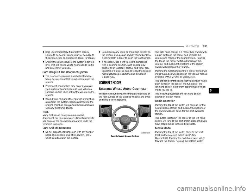
The remote sound system controls are located on
the rear surface of the steering wheel at the three
and nine o’clock positions.
Remote Sound System Controls
The right-hand control is a rocker-type switch with
a push button in the center and controls the
volume and mode of the sound system. Pushing
the top of the rocker switch will increase the
volume, and pushing the bottom of the rocker
switch will decrease the volume.
Pushing the right-hand control’s center button will
make the radio switch between the various modes
available (AM/FM/SXM or Media, etc.).
The left-hand control is a rocker-type switch with a
push button in the center. The function of the
left-hand control is different depending on which
mode you are in.
The following describes the left-hand control
operation in each mode:
Radio Operation
Pushing the top of the switch will seek up for the
next available station and pushing the bottom of
the switch will seek down for the next available
station.
The button located in the center of the left-hand
control will tune to the next preset station that you
have programmed in the radio presets.
Media Mode
Pushing the top of the switch skips to the next
track on the selected media (AUX/USB/
Bluetooth®). Pushing the switch up twice will go
forward two tracks. Pushing the bottom switch
5
23_JT_OM_EN_USC_t.book Page 233
Page 236 of 448
234MULTIMEDIA
goes to the beginning of the current track, or the
beginning of the previous track if it is within eight
seconds after the current track begins to play.
Double pressing the bottom button switch will skip
to the previous track if it is after eight seconds into
the current track.
RADIO MODE
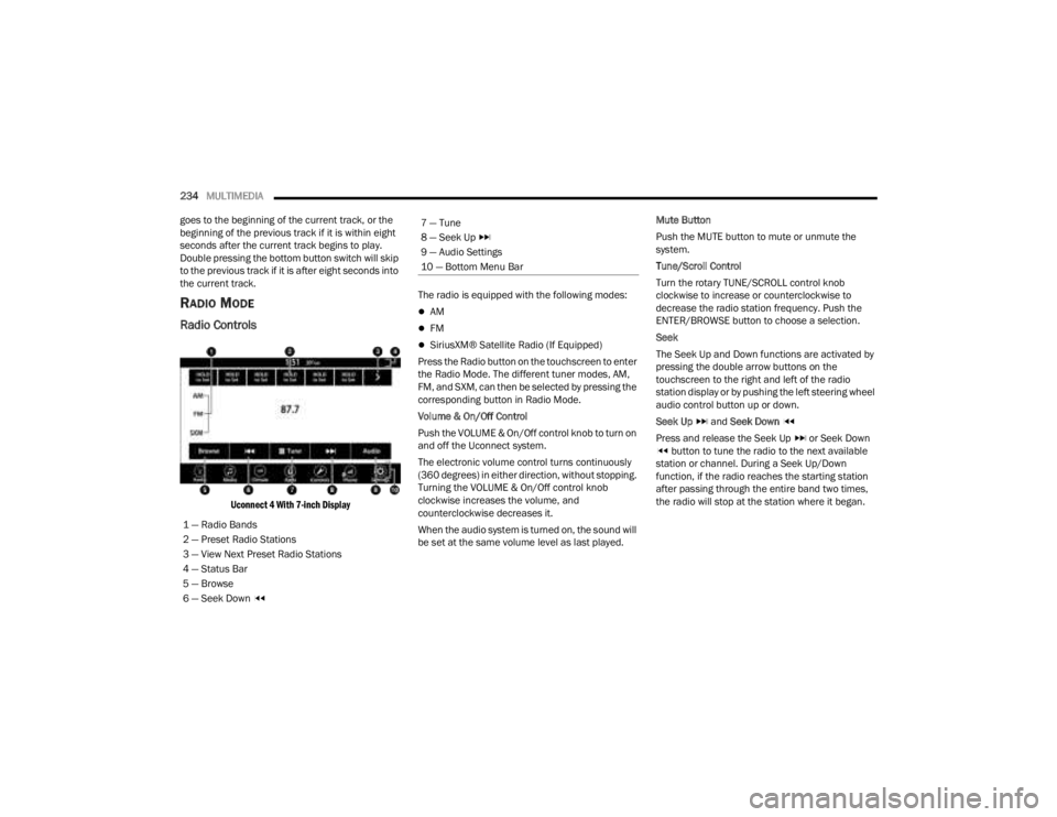
Radio Controls
Uconnect 4 With 7-inch Display
The radio is equipped with the following modes:
AM
FM
SiriusXM® Satellite Radio (If Equipped)
Press the Radio button on the touchscreen to enter
the Radio Mode. The different tuner modes, AM,
FM, and SXM, can then be selected by pressing the
corresponding button in Radio Mode.
Volume & On/Off Control
Push the VOLUME & On/Off control knob to turn on
and off the Uconnect system.
The electronic volume control turns continuously
(360 degrees) in either direction, without stopping.
Turning the VOLUME & On/Off control knob
clockwise increases the volume, and
counterclockwise decreases it.
When the audio system is turned on, the sound will
be set at the same volume level as last played. Mute Button
Push the MUTE button to mute or unmute the
system.
Tune/Scroll Control
Turn the rotary TUNE/SCROLL control knob
clockwise to increase or counterclockwise to
decrease the radio station frequency. Push the
ENTER/BROWSE button to choose a selection.
Seek
The Seek Up and Down functions are activated by
pressing the double arrow buttons on the
touchscreen to the right and left of the radio
station display or by pushing the left steering wheel
audio control button up or down.
Seek Up
and Seek Down
Press and release the Seek Up or Seek Down button to tune the radio to the next available
station or channel. During a Seek Up/Down
function, if the radio reaches the starting station
after passing through the entire band two times,
the radio will stop at the station where it began.
1 — Radio Bands
2 — Preset Radio Stations
3 — View Next Preset Radio Stations
4 — Status Bar
5 — Browse
6 — Seek Down
7 — Tune
8 — Seek Up
9 — Audio Settings
10 — Bottom Menu Bar
23_JT_OM_EN_USC_t.book Page 234
Page 338 of 448
336IN CASE OF EMERGENCY
PREPARATIONS FOR JACKING
1. Park on a firm, level surface. Avoid ice or
slippery areas.
2. Turn on the Hazard Warning Flashers.
3. Apply the parking brake.
4. Shift the automatic transmission into PARK (P), or a manual transmission into REVERSE.
5. Cycle the ignition to OFF.
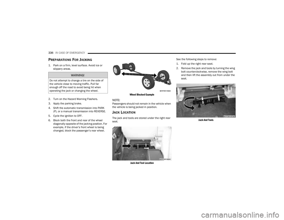
6. Block both the front and rear of the wheel diagonally opposite of the jacking position. For
example, if the driver’s front wheel is being
changed, block the passenger’s rear wheel.
Wheel Blocked Example
NOTE:Passengers should not remain in the vehicle when
the vehicle is being jacked in position.
JACK LOCATION
The jack and tools are stored under the right rear
seat.
Jack And Tool Location
See the following steps to remove:
1. Fold up the right rear seat.
2. Remove the jack and tools by turning the wing
bolt counterclockwise, remove the wing bolt
and then lift the assembly out from under the
seat.
Jack And Tools
WARNING!
Do not attempt to change a tire on the side of
the vehicle close to moving traffic. Pull far
enough off the road to avoid being hit when
operating the jack or changing the wheel.
23_JT_OM_EN_USC_t.book Page 336
Page 341 of 448
IN CASE OF EMERGENCY339
(Continued)
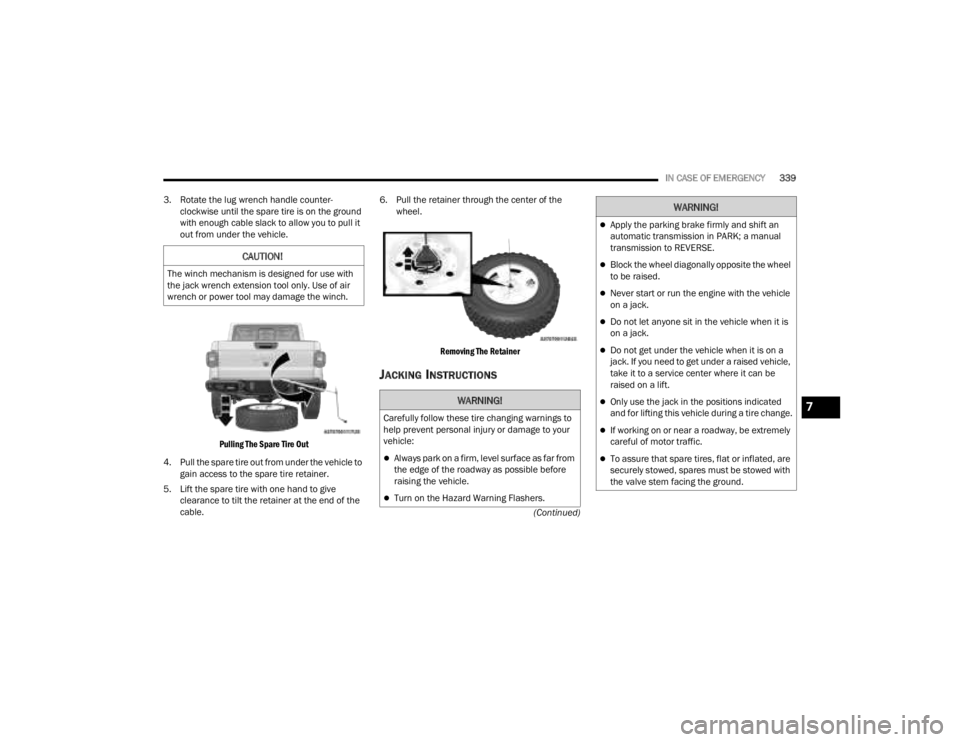
3. Rotate the lug wrench handle counter-
clockwise until the spare tire is on the ground
with enough cable slack to allow you to pull it
out from under the vehicle.
Pulling The Spare Tire Out
4. Pull the spare tire out from under the vehicle to gain access to the spare tire retainer.
5. Lift the spare tire with one hand to give clearance to tilt the retainer at the end of the
cable. 6. Pull the retainer through the center of the
wheel.
Removing The Retainer
JACKING INSTRUCTIONS
CAUTION!
The winch mechanism is designed for use with
the jack wrench extension tool only. Use of air
wrench or power tool may damage the winch.
WARNING!
Carefully follow these tire changing warnings to
help prevent personal injury or damage to your
vehicle:
Always park on a firm, level surface as far from
the edge of the roadway as possible before
raising the vehicle.
Turn on the Hazard Warning Flashers.
Apply the parking brake firmly and shift an
automatic transmission in PARK; a manual
transmission to REVERSE.
Block the wheel diagonally opposite the wheel
to be raised.
Never start or run the engine with the vehicle
on a jack.
Do not let anyone sit in the vehicle when it is
on a jack.
Do not get under the vehicle when it is on a
jack. If you need to get under a raised vehicle,
take it to a service center where it can be
raised on a lift.
Only use the jack in the positions indicated
and for lifting this vehicle during a tire change.
If working on or near a roadway, be extremely
careful of motor traffic.
To assure that spare tires, flat or inflated, are
securely stowed, spares must be stowed with
the valve stem facing the ground.
WARNING!
7
23_JT_OM_EN_USC_t.book Page 339
Page 342 of 448
340IN CASE OF EMERGENCY
Warning Label
1. Remove the spare tire, jack and tools from the stored location.
2. Using the lug wrench, loosen the wheel nuts (but do not remove) by turning them counter -
clockwise one turn while the wheel is still on
the ground.
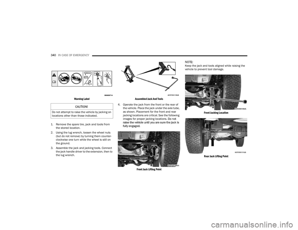
3. Assemble the jack and jacking tools. Connect the jack handle driver to the extension, then to
the lug wrench.
Assembled Jack And Tools
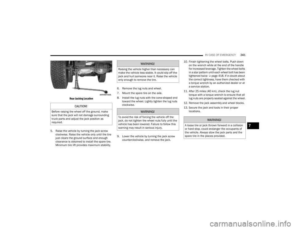
4. Operate the jack from the front or the rear of the vehicle. Place the jack under the axle tube,
as shown. Placement for the front and rear
jacking locations are critical. See the following
images for proper jacking locations. Do not
raise the vehicle until you are sure the jack is
fully engaged.
Front Jack Lifting Point
NOTE:Keep the jack and tools aligned while raising the
vehicle to prevent tool damage.
Front Jacking Location
Rear Jack Lifting Point
CAUTION!
Do not attempt to raise the vehicle by jacking on
locations other than those indicated.
23_JT_OM_EN_USC_t.book Page 340
Page 343 of 448
IN CASE OF EMERGENCY341
Rear Jacking Location
5. Raise the vehicle by turning the jack screw clockwise. Raise the vehicle only until the tire
just clears the ground surface and enough
clearance is obtained to install the spare tire.
Minimum tire lift provides maximum stability. 6. Remove the lug nuts and wheel.
7. Mount the spare tire on the axle.
8. Install the lug nuts with the cone-shaped end
toward the wheel. Lightly tighten the lug nuts
clockwise.
9. Lower the vehicle by turning the jack screw counterclockwise, and remove the jack. 10. Finish tightening the wheel bolts. Push down
on the wrench while at the end of the handle
for increased leverage. Tighten the wheel bolts
in a star pattern until each wheel bolt has been
tightened twice Úpage 418. If in doubt about
the correct tightness, have them checked with
a torque wrench by an authorized dealer or at
a service station.
11. After 25 miles (40 km), check the lug nut torque with a torque wrench to ensure that all
lug nuts are properly seated against the wheel.
12. Remove the jack assembly and wheel blocks.
13. Secure the jack and tools in their proper locations.
CAUTION!
Before raising the wheel off the ground, make
sure that the jack will not damage surrounding
truck parts and adjust the jack position as
required.
WARNING!
Raising the vehicle higher than necessary can
make the vehicle less stable. It could slip off the
jack and hurt someone near it. Raise the vehicle
only enough to remove the tire.
WARNING!
To avoid the risk of forcing the vehicle off the
jack, do not tighten the wheel nuts fully until the
vehicle has been lowered. Failure to follow this
warning may result in serious injury.WARNING!
A loose tire or jack thrown forward in a collision
or hard stop, could endanger the occupants of
the vehicle. Always stow the jack parts and the
spare tire in the places provided.7
23_JT_OM_EN_USC_t.book Page 341
Page 344 of 448
342IN CASE OF EMERGENCY
TO STOW THE FLAT OR SPARE
See the following steps for stowing the flat or spare
tire:
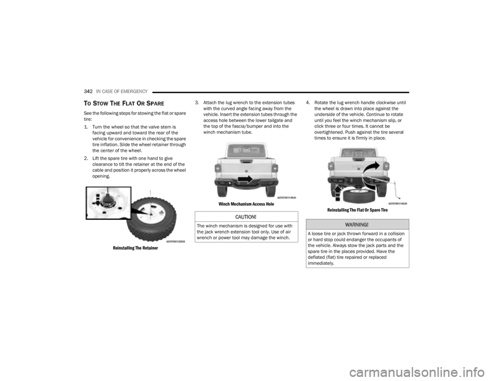
1. Turn the wheel so that the valve stem is
facing upward and toward the rear of the
vehicle for convenience in checking the spare
tire inflation. Slide the wheel retainer through
the center of the wheel.
2. Lift the spare tire with one hand to give clearance to tilt the retainer at the end of the
cable and position it properly across the wheel
opening.
Reinstalling The Retainer
3. Attach the lug wrench to the extension tubes
with the curved angle facing away from the
vehicle. Insert the extension tubes through the
access hole between the lower tailgate and
the top of the fascia/bumper and into the
winch mechanism tube.
Winch Mechanism Access Hole
4. Rotate the lug wrench handle clockwise until
the wheel is drawn into place against the
underside of the vehicle. Continue to rotate
until you feel the winch mechanism slip, or
click three or four times. It cannot be
overtightened. Push against the tire several
times to ensure it is firmly in place.
Reinstalling The Flat Or Spare Tire
CAUTION!
The winch mechanism is designed for use with
the jack wrench extension tool only. Use of air
wrench or power tool may damage the winch.WARNING!
A loose tire or jack thrown forward in a collision
or hard stop could endanger the occupants of
the vehicle. Always stow the jack parts and the
spare tire in the places provided. Have the
deflated (flat) tire repaired or replaced
immediately.
23_JT_OM_EN_USC_t.book Page 342
Page 345 of 448
IN CASE OF EMERGENCY343
REINSTALLING THE JACK AND TOOLS
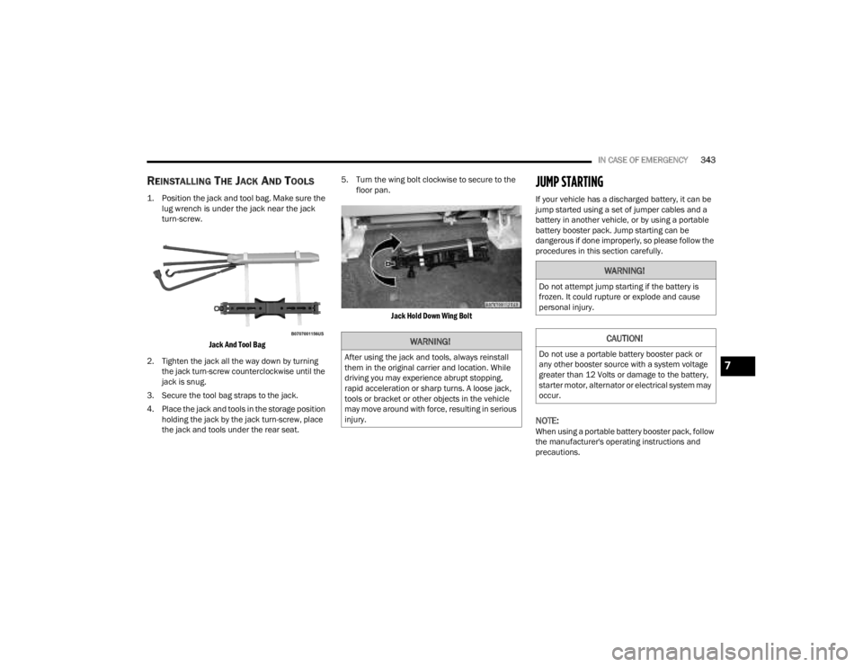
1. Position the jack and tool bag. Make sure the
lug wrench is under the jack near the jack
turn-screw.
Jack And Tool Bag
2. Tighten the jack all the way down by turning the jack turn-screw counterclockwise until the
jack is snug.
3. Secure the tool bag straps to the jack.
4. Place the jack and tools in the storage position holding the jack by the jack turn-screw, place
the jack and tools under the rear seat. 5. Turn the wing bolt clockwise to secure to the
floor pan.
Jack Hold Down Wing Bolt
JUMP STARTING
If your vehicle has a discharged battery, it can be
jump started using a set of jumper cables and a
battery in another vehicle, or by using a portable
battery booster pack. Jump starting can be
dangerous if done improperly, so please follow the
procedures in this section carefully.
NOTE:When using a portable battery booster pack, follow
the manufacturer's operating instructions and
precautions.
WARNING!
After using the jack and tools, always reinstall
them in the original carrier and location. While
driving you may experience abrupt stopping,
rapid acceleration or sharp turns. A loose jack,
tools or bracket or other objects in the vehicle
may move around with force, resulting in serious
injury.
WARNING!
Do not attempt jump starting if the battery is
frozen. It could rupture or explode and cause
personal injury.
CAUTION!
Do not use a portable battery booster pack or
any other booster source with a system voltage
greater than 12 Volts or damage to the battery,
starter motor, alternator or electrical system may
occur.
7
23_JT_OM_EN_USC_t.book Page 343