tailgate JEEP GLADIATOR 2023 User Guide
[x] Cancel search | Manufacturer: JEEP, Model Year: 2023, Model line: GLADIATOR, Model: JEEP GLADIATOR 2023Pages: 448, PDF Size: 17.37 MB
Page 114 of 448

112GETTING TO KNOW YOUR VEHICLE
There are two adjustable utility rail cleats on each
side of the bed that can be used to assist in
securing cargo.
Adjustable Cleat Assembly
Each utility rail cleat must be tightened down in
one of the detents along either utility rail in order to
keep cargo properly secured.
To move the utility rail cleat to any position on the
utility rail, turn the cleat retainer nut counter-
clockwise several times. Then, pull out on the
utility rail cleat and slide it to the detent nearest
the desired location. Make sure the utility rail cleat
is seated in the detent, and tighten the nut. To remove the utility rail cleats from the side utility
rails, slide the cleat to the rectangular cutout
located at the end of the rail toward the front of the
vehicle.
To remove the utility rail cleat from the front utility
rail, slide the cleat to the rectangular cutout
located on the left side of the rail.
TONNEAU COVER — IF EQUIPPED
The Tonneau Cover can be installed on the truck
bed to keep cargo out of view, and protect from
inclement weather.
The Tonneau Cover consists of the following
features:
Easy roll up cover
Tonneau fore/aft locator
Crossbar inside bed locator
Rear latches
Stowage straps
NOTE:The Tonneau Cover can be rolled up and secured
at the front of the truck bed without removing it
completely.
TONNEAU COVER INSTALLATION
To install the Tonneau Cover, proceed as follows:
1. Position the rolled up Tonneau Cover on the
truck bed and align it to the two fastener
locations at the front of the bed.
Fastener Locations
2. Using a #T50 Torx head driver, secure the fasteners to the bed.
3. Lower the tailgate to the fully open position before unrolling the Tonneau Cover.
1 — Utility Rail Detent
2 — Cleat Retainer Nut
3 — Utility Rail Cleat
23_JT_OM_EN_USC_t.book Page 112
Page 115 of 448
GETTING TO KNOW YOUR VEHICLE113
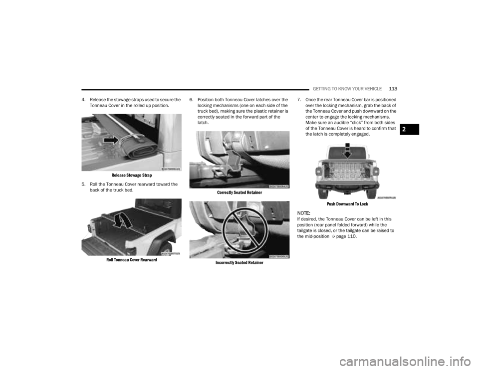
4. Release the stowage straps used to secure the Tonneau Cover in the rolled up position.
Release Stowage Strap
5. Roll the Tonneau Cover rearward toward the back of the truck bed.
Roll Tonneau Cover Rearward
6. Position both Tonneau Cover latches over the
locking mechanisms (one on each side of the
truck bed), making sure the plastic retainer is
correctly seated in the forward part of the
latch.
Correctly Seated Retainer
Incorrectly Seated Retainer
7. Once the rear Tonneau Cover bar is positioned
over the locking mechanism, grab the back of
the Tonneau Cover and push downward on the
center to engage the locking mechanisms.
Make sure an audible “click” from both sides
of the Tonneau Cover is heard to confirm that
the latch is completely engaged.
Push Downward To Lock
NOTE:If desired, the Tonneau Cover can be left in this
position (rear panel folded forward) while the
tailgate is closed, or the tailgate can be raised to
the mid-position Ú page 110.
2
23_JT_OM_EN_USC_t.book Page 113
Page 116 of 448
114GETTING TO KNOW YOUR VEHICLE
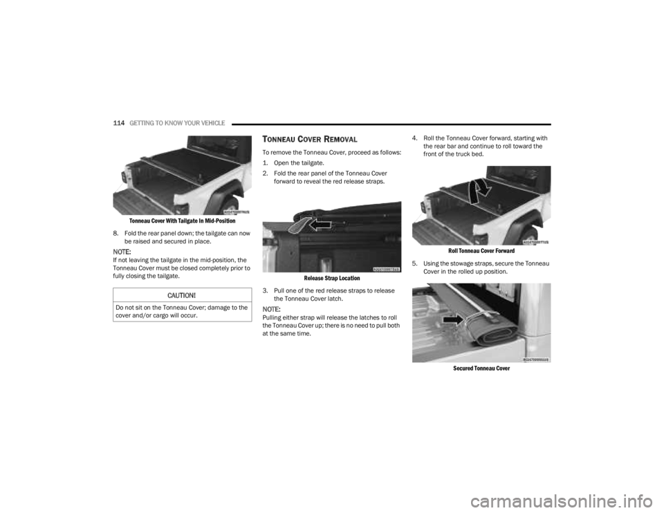
Tonneau Cover With Tailgate In Mid-Position
8. Fold the rear panel down; the tailgate can now be raised and secured in place.
NOTE:If not leaving the tailgate in the mid-position, the
Tonneau Cover must be closed completely prior to
fully closing the tailgate.
TONNEAU COVER REMOVAL
To remove the Tonneau Cover, proceed as follows:
1. Open the tailgate.
2. Fold the rear panel of the Tonneau Cover forward to reveal the red release straps.
Release Strap Location
3. Pull one of the red release straps to release the Tonneau Cover latch.
NOTE:Pulling either strap will release the latches to roll
the Tonneau Cover up; there is no need to pull both
at the same time. 4. Roll the Tonneau Cover forward, starting with
the rear bar and continue to roll toward the
front of the truck bed.
Roll Tonneau Cover Forward
5. Using the stowage straps, secure the Tonneau Cover in the rolled up position.
Secured Tonneau Cover
CAUTION!
Do not sit on the Tonneau Cover; damage to the
cover and/or cargo will occur.
23_JT_OM_EN_USC_t.book Page 114
Page 190 of 448
188STARTING AND OPERATING
(Continued)
PARKSENSE SYSTEM USAGE
P
RECAUTIONS
NOTE:
Ensure that the front and rear fascia/bumpers
are free of snow, ice, mud, dirt and debris to
keep the ParkSense system operating properly.
Jackhammers, large trucks, and other vibra -
tions could affect the performance of Park -
Sense.
When you turn the ParkSense system off, the
instrument cluster display will show a vehicle
graphic of the ParkSense on/off state for two
seconds. Furthermore, once you turn Park -
Sense off, it remains off until you turn it on
again, even if you cycle the ignition.
When you move the gear selector to the
REVERSE position and ParkSense is turned off,
the instrument cluster display will show the
“ParkSense OFF” message. This message will
be displayed for as long as the vehicle is in
REVERSE.
ParkSense, when on, will reduce the volume of
the radio when it is sounding a tone.
Clean the ParkSense sensors regularly, taking
care not to scratch or damage them. The
sensors must not be covered with ice, snow,
slush, mud, dirt or debris. Failure to do so can
result in the system not working properly. The ParkSense system might not detect an obstacle
behind or in front of the fascia/bumper, or it
could provide a false indication that an obstacle
is behind or in front of the fascia/bumper.
Use the ParkSense switch to turn the ParkSense
system off if obstacles such as bicycle carriers,
trailer hitches, etc. are placed within 12 inches
(30 cm) of the rear fascia/bumper. Failure to do
so can result in the system misinterpreting a
close obstacle as a sensor problem, causing the
“PARKSENSE UNAVAILABLE SERVICE
REQUIRED” message to appear in the instru
-
ment cluster display.
ParkSense should be disabled when the tailgate
is in the lowered or open position. A lowered tail -
gate could provide a false indication that an
obstacle is behind the vehicle.
WARNING!
Drivers must be careful when backing up even
when using ParkSense. Always check carefully
behind your vehicle, look behind you, and be
sure to check for pedestrians, animals, other
vehicles, obstructions, and blind spots before
backing up. You are responsible for safety and
must continue to pay attention to your
surroundings. Failure to do so can result in
serious injury or death.
Before using ParkSense, it is strongly recom -
mended that the ball mount and hitch ball
assembly be disconnected from the vehicle
when the vehicle is not used for towing.
Failure to do so can result in injury or damage
to vehicles or obstacles because the hitch ball
will be much closer to the obstacle than the
rear fascia/bumper when the vehicle sounds
the continuous tone. Also, the sensors could
detect the ball mount and hitch ball assembly,
depending on its size and shape, giving a false
indication that an obstacle is behind the
vehicle.
CAUTION!
ParkSense is only a parking aid and it is
unable to recognize every obstacle, including
small obstacles. Parking curbs might be
temporarily detected or not detected at all.
Obstacles located above or below the sensors
will not be detected when they are in close
proximity.
The vehicle must be driven slowly when using
ParkSense in order to be able to stop in time
when an obstacle is detected. It is recom -
mended that the driver looks over his/her
shoulder when using ParkSense.
WARNING!
23_JT_OM_EN_USC_t.book Page 188
Page 191 of 448
STARTING AND OPERATING189
PARKVIEW REAR BACK UP CAMERA
The ParkView Rear Back Up Camera allows you to
see an on-screen image of the rear surroundings of
your vehicle whenever the gear selector is in
REVERSE. The image will be displayed in the
touchscreen display along with a caution note to
“Check Entire Surroundings” across the top of the
screen. After five seconds this note will disappear.
The ParkView camera is located on the tailgate,
above the vehicle license plate.
NOTE:Removing the tailgate will disable the rearview
camera function.
Manual Activation Of The Rear View Camera
1. Go to the Controls screen by pressing the
Controls button located on the bottom of the
Uconnect display, and then press Back Up
Camera.
2. Press the Back Up Camera button to turn the Rear View Camera system on.
When the vehicle is shifted out of REVERSE with
Camera delay turned off, the rear Camera mode is
exited and the previous screen appears again.
When the vehicle is shifted out of REVERSE with
Camera delay turned on, the rear Camera image
will be displayed for up to 10 seconds unless the
vehicle speed exceeds 8 mph (13 km/h), the transmission is shifted into PARK, the ignition is
placed in the OFF position, or the touchscreen X
button to disable display of the Rear View Camera
image is pressed.
Whenever the Rear View Camera image is
activated through the Back Up Camera button in
the Controls menu, and the vehicle speed is
greater than, or equal to 8 mph (13 km/h), a
display timer for the image is initiated. The image
will continue to be displayed until the display timer
exceeds 10 seconds.NOTE:
If the vehicle speed remains below 8 mph
(13 km/h), the Rear View Camera image will be
displayed continuously until deactivated via the
touchscreen X button, the transmission is
shifted into PARK, or the ignition is placed in the
OFF position.
The touchscreen X button to disable display of
the camera image is made available ONLY when
the vehicle is not in REVERSE.
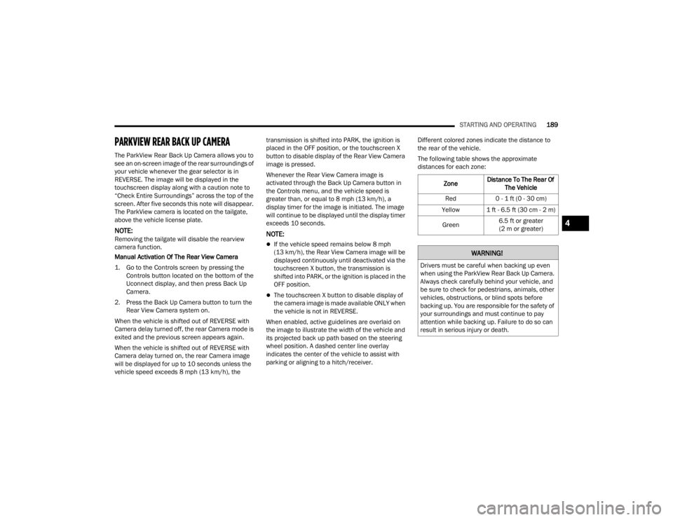
When enabled, active guidelines are overlaid on
the image to illustrate the width of the vehicle and
its projected back up path based on the steering
wheel position. A dashed center line overlay
indicates the center of the vehicle to assist with
parking or aligning to a hitch/receiver. Different colored zones indicate the distance to
the rear of the vehicle.
The following table shows the approximate
distances for each zone:
Zone Distance To The Rear Of
The Vehicle
Red 0 - 1 ft (0 - 30 cm)
Yellow 1 ft - 6.5 ft (30 cm - 2 m)
Green 6.5 ft or greater
(2 m or greater)
WARNING!
Drivers must be careful when backing up even
when using the ParkView Rear Back Up Camera.
Always check carefully behind your vehicle, and
be sure to check for pedestrians, animals, other
vehicles, obstructions, or blind spots before
backing up. You are responsible for the safety of
your surroundings and must continue to pay
attention while backing up. Failure to do so can
result in serious injury or death.
4
23_JT_OM_EN_USC_t.book Page 189
Page 339 of 448
IN CASE OF EMERGENCY337
(Continued)
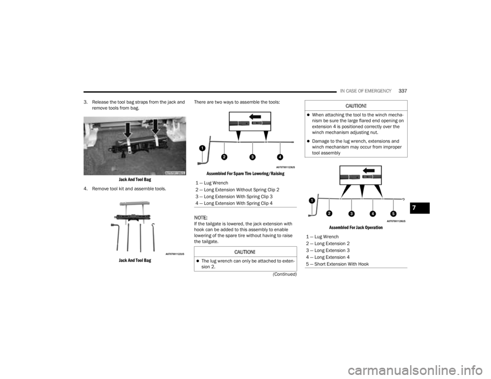
3. Release the tool bag straps from the jack and
remove tools from bag.
Jack And Tool Bag
4. Remove tool kit and assemble tools.
Jack And Tool Bag
There are two ways to assemble the tools:
Assembled For Spare Tire Lowering/Raising
NOTE:If the tailgate is lowered, the jack extension with
hook can be added to this assembly to enable
lowering of the spare tire without having to raise
the tailgate.
Assembled For Jack Operation
1 — Lug Wrench
2 — Long Extension Without Spring Clip 2
3 — Long Extension With Spring Clip 3
4 — Long Extension With Spring Clip 4
CAUTION!
The lug wrench can only be attached to exten
-
sion 2.
When attaching the tool to the winch mecha -
nism be sure the large flared end opening on
extension 4 is positioned correctly over the
winch mechanism adjusting nut.
Damage to the lug wrench, extensions and
winch mechanism may occur from improper
tool assembly
1 — Lug Wrench
2 — Long Extension 2
3 — Long Extension 3
4 — Long Extension 4
5 — Short Extension With Hook
CAUTION!
7
23_JT_OM_EN_USC_t.book Page 337
Page 340 of 448

338IN CASE OF EMERGENCY
SPARE TIRE LOCATION AND REMOVAL
Remove the spare tire before attempting to jack up
the truck. The spare tire is secured under the rear
of the vehicle with a winch and cable mechanism.
Spare Tire Location
For spare tire removal, see the following steps:
1. Locate the winch access hole at the rear of
the vehicle.
Access Hole Location
2. Attach the lug wrench to the extension tubes with the curved angle facing away from the
vehicle. Insert the extension tube through the
access hole between the lower tailgate and
the top of the fascia/bumper and into the
winch mechanism tube.
Winch Mechanism Tube
Inserting The Extensions Into The Winch Mechanism Access Hole
WARNING!
After using the jack and tools, always reinstall
them in the original carrier and location. While
driving you may experience abrupt stopping,
rapid acceleration or sharp turns. A loose jack,
tools, bracket or other objects in the vehicle may
move around with force, resulting in serious
injury.
23_JT_OM_EN_USC_t.book Page 338
Page 344 of 448
342IN CASE OF EMERGENCY
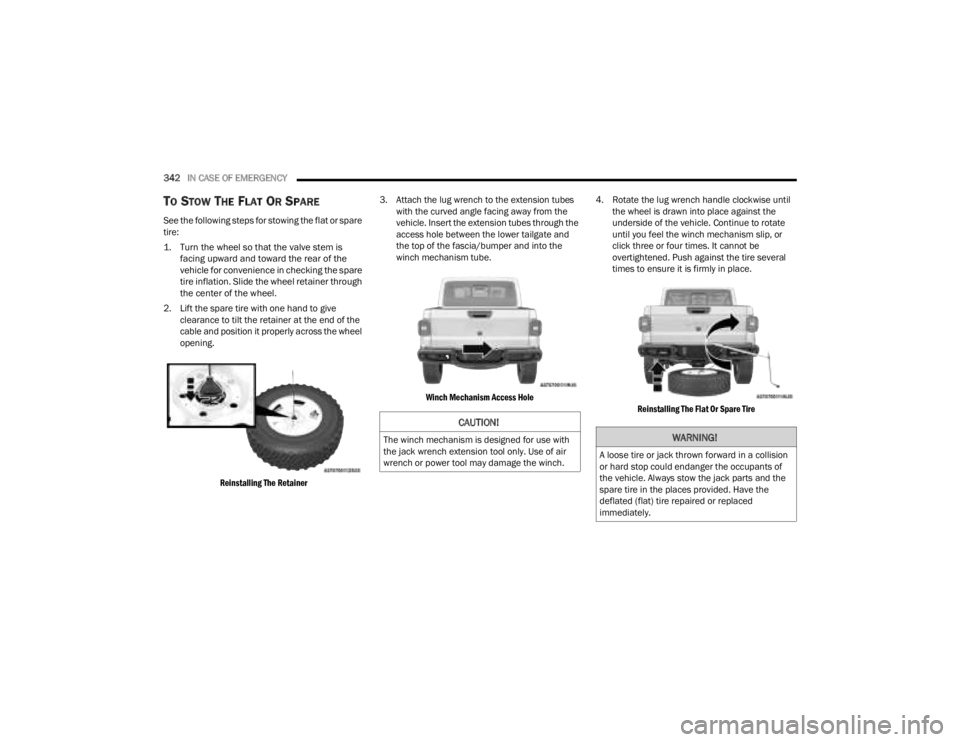
TO STOW THE FLAT OR SPARE
See the following steps for stowing the flat or spare
tire:
1. Turn the wheel so that the valve stem is
facing upward and toward the rear of the
vehicle for convenience in checking the spare
tire inflation. Slide the wheel retainer through
the center of the wheel.
2. Lift the spare tire with one hand to give clearance to tilt the retainer at the end of the
cable and position it properly across the wheel
opening.
Reinstalling The Retainer
3. Attach the lug wrench to the extension tubes
with the curved angle facing away from the
vehicle. Insert the extension tubes through the
access hole between the lower tailgate and
the top of the fascia/bumper and into the
winch mechanism tube.
Winch Mechanism Access Hole
4. Rotate the lug wrench handle clockwise until
the wheel is drawn into place against the
underside of the vehicle. Continue to rotate
until you feel the winch mechanism slip, or
click three or four times. It cannot be
overtightened. Push against the tire several
times to ensure it is firmly in place.
Reinstalling The Flat Or Spare Tire
CAUTION!
The winch mechanism is designed for use with
the jack wrench extension tool only. Use of air
wrench or power tool may damage the winch.WARNING!
A loose tire or jack thrown forward in a collision
or hard stop could endanger the occupants of
the vehicle. Always stow the jack parts and the
spare tire in the places provided. Have the
deflated (flat) tire repaired or replaced
immediately.
23_JT_OM_EN_USC_t.book Page 342
Page 376 of 448
374SERVICING AND MAINTENANCE
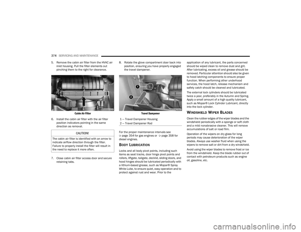
5. Remove the cabin air filter from the HVAC air inlet housing. Pull the filter elements out
pinching them to the right for clearance.
Cabin Air Filter
6. Install the cabin air filter with the air filter position indicators pointing in the same
direction as removal.
7. Close cabin air filter access door and secure retaining tabs. 8. Rotate the glove compartment door back into
position, ensuring you have properly engaged
the travel dampener.
Travel Dampener
For the proper maintenance intervals see
Ú page 354 for gas engines or Ú page 358 for
diesel engines.
BODY LUBRICATION
Locks and all body pivot points, including such
items as seat tracks, door hinge pivot points and
rollers, liftgate, tailgate, decklid, sliding doors, and
hood hinges should be lubricated periodically with
a lithium-based grease, such as Mopar® Spray
White Lube, to ensure quiet, easy operation and to
protect against rust and wear. Prior to the application of any lubricant, the parts concerned
should be wiped clean to remove dust and grit.
After lubricating, excess oil and grease should be
removed. Particular attention should also be given
to hood latching components to ensure proper
function. When performing other underhood
services, the hood latch, release mechanism and
safety catch should be cleaned and lubricated.
The external lock cylinders should be lubricated
twice a year, preferably in the Autumn and Spring.
Apply a small amount of a high quality lubricant,
such as Mopar® Lock Cylinder Lubricant, directly
into the lock cylinder.
WINDSHIELD WIPER BLADES
Clean the rubber edges of the wiper blades and the
windshield periodically with a sponge or soft cloth
and a mild nonabrasive cleaner. This will remove
accumulations of salt or road film.
Operation of the wipers on dry glass for long
periods may cause deterioration of the wiper
blades. Always use washer fluid when using the
wipers to remove salt or dirt from a dry windshield.
Avoid using the wiper blades to remove frost or ice
from the windshield. Keep the blade rubber out of
contact with petroleum products such as engine
oil, gasoline, etc.
CAUTION!
The cabin air filter is identified with an arrow to
indicate airflow direction through the filter.
Failure to properly install the filter will result in
the need to replace it more often.
1 — Travel Dampener Housing
2 — Travel Dampener Rod
23_JT_OM_EN_USC_t.book Page 374
Page 397 of 448
SERVICING AND MAINTENANCE395
LED Front Fog Lamp
If your vehicle is equipped with LED fog lamps they
are replaced as an assembly.
NOTE:We recommend seeing an authorized dealer for
service.
REAR TAIL, STOP, TURN SIGNAL, AND BACKUP
LAMP — IF EQUIPPED
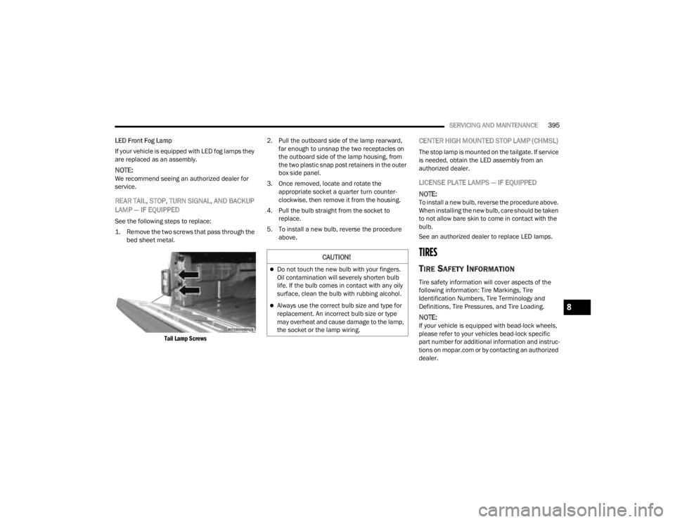
See the following steps to replace:
1. Remove the two screws that pass through the bed sheet metal.
Tail Lamp Screws
2. Pull the outboard side of the lamp rearward,
far enough to unsnap the two receptacles on
the outboard side of the lamp housing, from
the two plastic snap post retainers in the outer
box side panel.
3. Once removed, locate and rotate the appropriate socket a quarter turn counter -
clockwise, then remove it from the housing.
4. Pull the bulb straight from the socket to replace.
5. To install a new bulb, reverse the procedure above.
CENTER HIGH MOUNTED STOP LAMP (CHMSL)
The stop lamp is mounted on the tailgate. If service
is needed, obtain the LED assembly from an
authorized dealer.
LICENSE PLATE LAMPS — IF EQUIPPED
NOTE:
To install a new bulb, reverse the procedure above.
When installing the new bulb, care should be taken
to not allow bare skin to come in contact with the
bulb.
See an authorized dealer to replace LED lamps.
TIRES
TIRE SAFETY INFORMATION
Tire safety information will cover aspects of the
following information: Tire Markings, Tire
Identification Numbers, Tire Terminology and
Definitions, Tire Pressures, and Tire Loading.
NOTE:If your vehicle is equipped with bead-lock wheels,
please refer to your vehicles bead-lock specific
part number for additional information and instruc -
tions on mopar.com or by contacting an authorized
dealer.
CAUTION!
Do not touch the new bulb with your fingers.
Oil contamination will severely shorten bulb
life. If the bulb comes in contact with any oily
surface, clean the bulb with rubbing alcohol.
Always use the correct bulb size and type for
replacement. An incorrect bulb size or type
may overheat and cause damage to the lamp,
the socket or the lamp wiring.8
23_JT_OM_EN_USC_t.book Page 395