key JEEP GRAND CHEROKEE 2012 Owner handbook (in English)
[x] Cancel search | Manufacturer: JEEP, Model Year: 2012, Model line: GRAND CHEROKEE, Model: JEEP GRAND CHEROKEE 2012Pages: 380, PDF Size: 3.21 MB
Page 227 of 380
When parking on a hill, apply the parking brake
before placing the shift lever in PARK, other-
wise the load on the transmission locking
mechanism may make it difficult to move the
shift lever out of PARK. As an added precau-
tion, turn the front wheels toward the curb on a
downhill grade and away from the curb on an
uphill grade.
WARNING!
•Never use the PARK position as a substi-
tute for the parking brake. Always apply the
parking brake fully when parked to guard
against vehicle movement and possible
injury or damage.
• Your vehicle could move and injure you and
others if it is not completely in PARK.
Check by trying to move the shift lever
rearward (with the brake pedal released),
after you have placed it in PARK. Make
sure the transmission is in PARK before
leaving the vehicle.
(Continued)
WARNING!(Continued)
•It is dangerous to move the shift lever out of
PARK or NEUTRAL if the engine speed is
higher than idle speed. If your foot is not firmly
pressing the brake pedal, the vehicle could
accelerate quickly forward or in reverse. You
could lose control of the vehicle and hit some-
one or something. Only shift into gear when
the engine is idling normally and when your
foot is firmly pressing the brake pedal.
• Unintended movement of a vehicle could
injure those in or near the vehicle. As with
all vehicles, you should never exit a vehicle
while the engine is running. Before exiting a
vehicle, always apply the parking brake,
shift the transmission into PARK, and re-
move the key fob. Once the key fob is
removed, the shift lever is locked in the
PARK position, securing the vehicle
against unwanted movement.
• When leaving the vehicle, always remove
the key fob and lock your vehicle.
(Continued)
WARNING!(Continued)
• Never leave children alone in a vehicle, or
with access to an unlocked vehicle.
• Allowing children to be in a vehicle unat-
tended is dangerous for a number of rea-
sons. A child or others could be seriously or
fatally injured. Children should be warned
not to touch the parking brake, brake pedal
or the shift lever. Do not leave the key fob in
or near the vehicle, and do not leave Key-
less Enter-N-Go in the ACC or ON/RUN
mode. A child could operate power win-
dows, other controls, or move the vehicle.
CAUTION!
•Before moving the shift lever out of PARK,
you must turn the ignition switch from the
LOCK/OFF position to the ON/RUN posi-
tion, and also press the brake pedal. Oth-
erwise, damage to the shift lever could
result.
(Continued)
223
Page 231 of 380
When parking on a hill, apply the parking brake
before placing the shift lever in PARK, other-
wise the load on the transmission locking
mechanism may make it difficult to move the
shift lever out of PARK. As an added precau-
tion, turn the front wheels toward the curb on a
downhill grade and away from the curb on an
uphill grade.
WARNING!
•Never use the PARK position as a substi-
tute for the parking brake. Always apply the
parking brake fully when parked to guard
against vehicle movement and possible
injury or damage.
• Your vehicle could move and injure you and
others if it is not completely in PARK.
Check by trying to move the shift lever
rearward (with the brake pedal released),
after you have placed it in PARK. Make
sure the transmission is in PARK before
leaving the vehicle.
(Continued)
WARNING!(Continued)
•It is dangerous to move the shift lever out of
PARK or NEUTRAL if the engine speed is
higher than idle speed. If your foot is not firmly
pressing the brake pedal, the vehicle could
accelerate quickly forward or in reverse. You
could lose control of the vehicle and hit some-
one or something. Only shift into gear when
the engine is idling normally and when your
foot is firmly pressing the brake pedal.
• Unintended movement of a vehicle could
injure those in or near the vehicle. As with
all vehicles, you should never exit a vehicle
while the engine is running. Before exiting a
vehicle, always apply the parking brake,
shift the transmission into PARK, and re-
move the key fob. Once the key fob is
removed, the shift lever is locked in the
PARK position, securing the vehicle
against unwanted movement.
• When leaving the vehicle, always remove
the key fob and lock your vehicle.
(Continued)
WARNING!(Continued)
• Never leave children alone in a vehicle, or
with access to an unlocked vehicle. Allow-
ing children to be in a vehicle unattended is
dangerous for a number of reasons. A child
or others could be seriously or fatally in-
jured. Children should be warned not to
touch the parking brake, brake pedal or the
shift lever. Do not leave the key fob in or
near the vehicle, and do not leave Keyless
Enter-N-Go in the ACC or ON/RUN mode.
A child could operate power windows, other
controls, or move the vehicle.
CAUTION!
•Before moving the shift lever out of PARK,
you must turn the ignition switch from the
LOCK/OFF position to the ON/RUN posi-
tion, and also press the brake pedal. Oth-
erwise, damage to the shift lever could
result.
(Continued)
227
Page 249 of 380
WARNING!(Continued)
• When leaving the vehicle, always remove
the key fob from the ignition and lock your
vehicle. Never leave children alone in a
vehicle, or with access to an unlocked
vehicle. Allowing children to be in a vehicle
unattended is dangerous for a number of
reasons. A child or others could be seri-
ously or fatally injured. Children should be
warned not to touch the parking brake,
brake pedal or the shift lever.
• Do not leave the key fob in or near the
vehicle, and do not leave Keyless Enter-
N-Go in the ACC or ON/RUN mode. A child
could operate power windows, other con-
trols, or move the vehicle.
• Be sure the parking brake is fully disen-
gaged before driving; failure to do so can
lead to brake failure and a collision.
(Continued)WARNING!(Continued)
• Always fully apply the parking brake when
leaving your vehicle, or it may roll and
cause damage or injury. Also be certain to
leave the transmission in PARK. Failure to
do so may allow the vehicle to roll and
cause damage or injury.
CAUTION!
If the “Brake Warning Light” remains on with
the parking brake released, a brake system
malfunction is indicated. Have the brake sys-
tem serviced by an authorized dealer imme-
diately.
ELECTRONIC BRAKE CONTROL
SYSTEM
Your vehicle is equipped with an advanced
electronic brake control system that includes
the Anti-Lock Brake System (ABS), Traction
Control System (TCS), Brake Assist System
(BAS), Electronic Roll Mitigation (ERM), and
Electronic Stability Control (ESC). All five of
these systems work together to enhance ve-
hicle stability and control in various driving
conditions.
Also, your vehicle is equipped with Trailer Sway
Control (TSC), Hill Start Assist (HSA), Brake
Lock Differential (BLD), Ready Alert Braking,
Rain Brake Support and, if it has four-wheel
drive with the MP 3023 two-speed transfer
case, Hill Descent Control (HDC).
Anti-Lock Brake System (ABS)
This system aids the driver in maintaining ve-
hicle control under adverse braking conditions.
The system controls hydraulic brake pressure
to prevent wheel lock-up and help avoid skid-
ding on slippery surfaces during braking.
245
Page 282 of 380
1. Bring the vehicle to a complete stop and
shift the transmission to PARK.
2. Turn the engine OFF.
3. For vehicles with Keyless Enter-N-Go, re-
move the Keyless Enter-N-Go button and use
the key fob to complete this procedure. Refer to
“Starting Procedures/Keyless Enter-N-Go” in
“Starting and Operating” for further information.
4. Turn the ignition switch to the ON/RUN po-
sition, but do not start the engine.
5. Press and hold the brake pedal.
6. Shift the transmission into NEUTRAL.
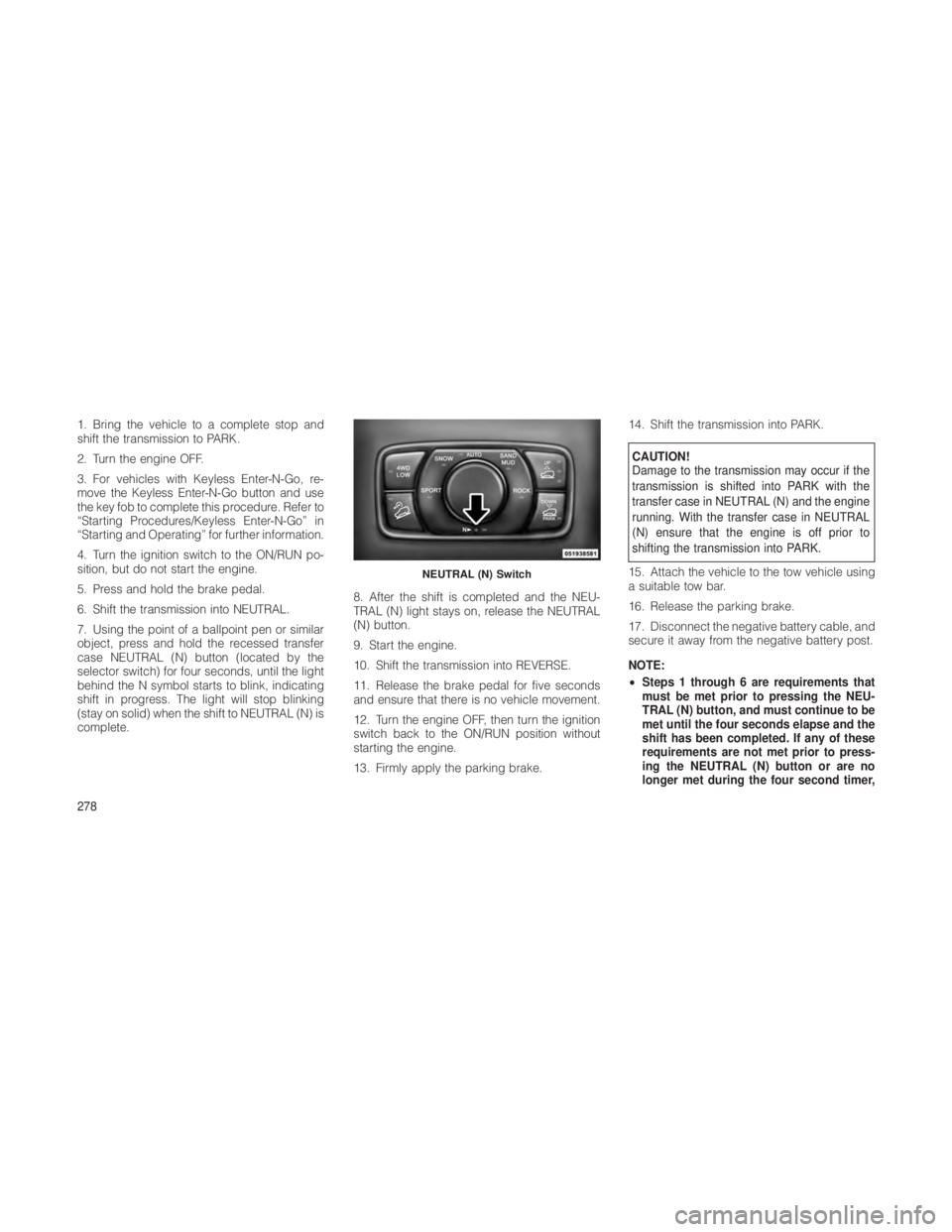
7. Using the point of a ballpoint pen or similar
object, press and hold the recessed transfer
case NEUTRAL (N) button (located by the
selector switch) for four seconds, until the light
behind the N symbol starts to blink, indicating
shift in progress. The light will stop blinking
(stay on solid) when the shift to NEUTRAL (N) is
complete.8. After the shift is completed and the NEU-
TRAL (N) light stays on, release the NEUTRAL
(N) button.
9. Start the engine.
10. Shift the transmission into REVERSE.
11. Release the brake pedal for five seconds
and ensure that there is no vehicle movement.
12. Turn the engine OFF, then turn the ignition
switch back to the ON/RUN position without
starting the engine.
13. Firmly apply the parking brake.14. Shift the transmission into PARK.
CAUTION!
Damage to the transmission may occur if the
transmission is shifted into PARK with the
transfer case in NEUTRAL (N) and the engine
running. With the transfer case in NEUTRAL
(N) ensure that the engine is off prior to
shifting the transmission into PARK.
15. Attach the vehicle to the tow vehicle using
a suitable tow bar.
16. Release the parking brake.
17. Disconnect the negative battery cable, and
secure it away from the negative battery post.
NOTE:
• Steps 1 through 6 are requirements that
must be met prior to pressing the NEU-
TRAL (N) button, and must continue to be
met until the four seconds elapse and the
shift has been completed. If any of these
requirements are not met prior to press-
ing the NEUTRAL (N) button or are no
longer met during the four second timer,
NEUTRAL (N) Switch
278
Page 284 of 380
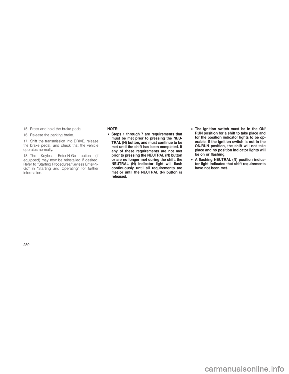
15. Press and hold the brake pedal.
16. Release the parking brake.
17. Shift the transmission into DRIVE, release
the brake pedal, and check that the vehicle
operates normally.
18. The Keyless Enter-N-Go button (if
equipped) may now be reinstalled if desired.
Refer to “Starting Procedures/Keyless Enter-N-
Go” in “Starting and Operating” for further
information.NOTE:
•
Steps 1 through 7 are requirements that
must be met prior to pressing the NEU-
TRAL (N) button, and must continue to be
met until the shift has been completed. If
any of these requirements are not met
prior to pressing the NEUTRAL (N) button
or are no longer met during the shift, the
NEUTRAL (N) indicator light will flash
continuously until all requirements are
met or until the NEUTRAL (N) button is
released. •
The ignition switch must be in the ON/
RUN position for a shift to take place and
for the position indicator lights to be op-
erable. If the ignition switch is not in the
ON/RUN position, the shift will not take
place and no position indicator lights will
be on or flashing.
• A flashing NEUTRAL (N) position indica-
tor light indicates that shift requirements
have not been met.
280
Page 285 of 380
6
WHAT TO DO IN EMERGENCIES
•HAZARD WARNING FLASHERS ................. 282
• IF YOUR ENGINE OVERHEATS .................. 282
• JACKING AND TIRE CHANGING ................. 283
• Jack Location .......................... 283
• Spare Tire Stowage ....................... 283
• Preparations For Jacking ................... 283
• Jacking Instructions ...................... 284
• Road Tire Installation ...................... 287
• JUMP-STARTING .......................... 287
• Preparations For Jump-Start ................. 288
• Jump-Starting Procedure ................... 288
• FREEING A STUCK VEHICLE ................... 289
• TOW EYES .............................. 290
• SHIFT LEVER OVERRIDE ..................... 290
• TOWING A DISABLED VEHICLE ................. 291
• Towing Without The Ignition Key Fob ............ 293
• Four-Wheel Drive Vehicles ................... 293
281
Page 297 of 380
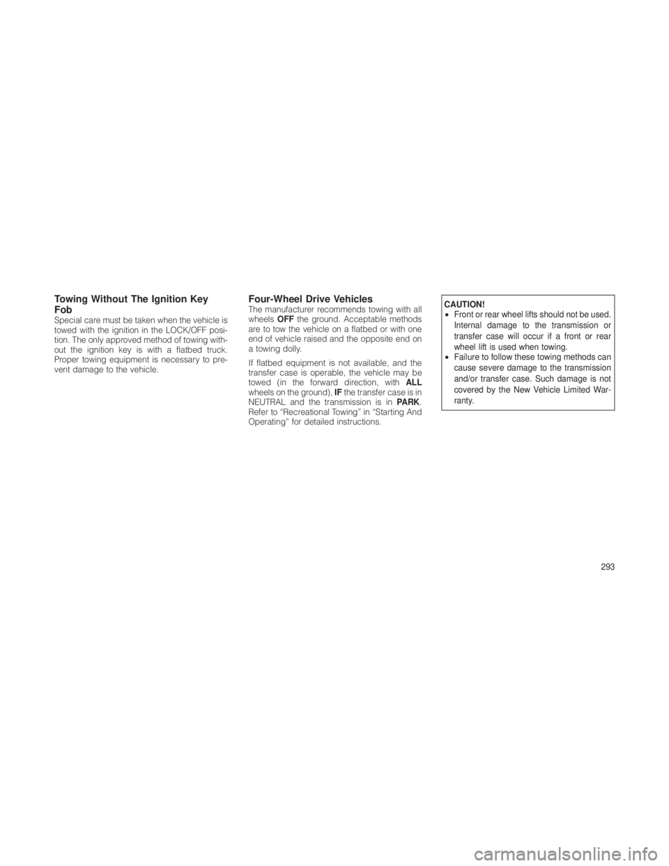
Towing Without The Ignition Key
Fob
Special care must be taken when the vehicle is
towed with the ignition in the LOCK/OFF posi-
tion. The only approved method of towing with-
out the ignition key is with a flatbed truck.
Proper towing equipment is necessary to pre-
vent damage to the vehicle.
Four-Wheel Drive VehiclesThe manufacturer recommends towing with all
wheelsOFFthe ground. Acceptable methods
are to tow the vehicle on a flatbed or with one
end of vehicle raised and the opposite end on
a towing dolly.
If flatbed equipment is not available, and the
transfer case is operable, the vehicle may be
towed (in the forward direction, with ALL
wheels on the ground), IFthe transfer case is in
NEUTRAL and the transmission is in PARK.
Refer to “Recreational Towing” in “Starting And
Operating” for detailed instructions.CAUTION!
• Front or rear wheel lifts should not be used.
Internal damage to the transmission or
transfer case will occur if a front or rear
wheel lift is used when towing.
• Failure to follow these towing methods can
cause severe damage to the transmission
and/or transfer case. Such damage is not
covered by the New Vehicle Limited War-
ranty.
293
Page 324 of 380
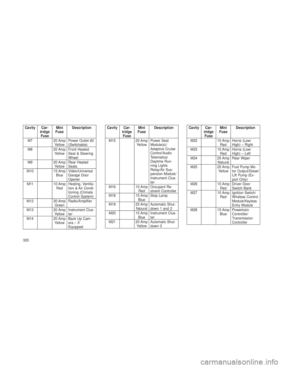
Cavity Car-tridgeFuse Mini
Fuse Description
M7 20 Amp YellowPower Outlet #2
(Switchable)
M8 20 Amp
Yellow Front Heated
Seat & Steering
Wheel
M9 20 Amp
Yellow Rear Heated
Seats
M10 15 Amp
Blue Video/Universal
Garage Door
Opener
M11 10 Amp
Red Heating, Ventila-
tion & Air Condi-
tioning (Climate
Control System)
M12 30 Amp
Green Radio/Amplifier
M13 20 Amp
Yellow Instrument Clus-
ter
M14 20 Amp
Yellow Back Up Cam-
era–If
EquippedCavity Car-
tridgeFuse Mini
Fuse Description
M15 20 Amp YellowPower Seat
Module(s)/
Adaptive Cruise
Control/Audio
Telematics/
Daytime Run-
ning Lights
Relay/Air Sus-
pension Module/
Instrument Clus-
ter
M16 10 Amp RedOccupant Re-
straint Controller
M18 15 Amp
Blue Stop Lamp
M19 25 Amp
Natural Automatic Shut-
down 1 and 2
M20 15 Amp BlueInstrument Clus-
ter
M21 20 Amp YellowAutomatic Shut-
down 3Cavity Car-
tridgeFuse Mini
Fuse Description
M22 10 Amp RedHorns (Low/
High) – Right
M23 10 Amp
Red Horns (Low/
High) – Left
M24 25 Amp
Natural Rear Wiper
M25 20 Amp
Yellow Fuel Pump Mo-
tor Output/Diesel
Lift Pump (Ex-
port Only)
M26 10 Amp
Red Driver Door
Switch Bank
M27 10 Amp RedIgnition Switch/
Wireless Control
Module/Keyless
Entry Module
M28 15 Amp
Blue Powertrain
Controller/
Transmission
Controller
320
Page 326 of 380
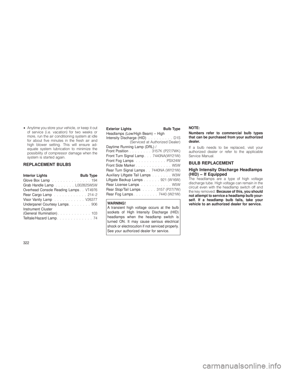
•Anytime you store your vehicle, or keep it out
of service (i.e. vacation) for two weeks or
more, run the air conditioning system at idle
for about five minutes in the fresh air and
high blower setting. This will ensure ad-
equate system lubrication to minimize the
possibility of compressor damage when the
system is started again.
REPLACEMENT BULBS
Interior Lights Bulb Type
Glove Box Lamp ..............194
Grab Handle Lamp .......L002825W5W
Overhead Console Reading Lamps . . VT4976
Rear Cargo Lamp ............ 214–2
Visor Vanity Lamp ...........V26377
Underpanel Courtesy Lamps ........906
Instrument Cluster
(General Illumination) ............103
Telltale/Hazard Lamp .............74 Exterior Lights
Bulb Type
Headlamps (Low/High Beam) – High
Intensity Discharge (HID) .........D1S
(Serviced at Authorized Dealer)
Daytime Running Lamp (DRL) /
Front Position ........3157K (P27/7WK)
Front Turn Signal Lamp . . . 7440NA(WY21W)
Front Fog Lamps ........... PSX24W
Front Side Marker .............W5W
Rear Turn Signal Lamps . . 7440NA (WY21W)
Auxiliary Liftgate Tail Lamps .......W3W
Liftgate Backup Lamps ......921(W16W)
Rear License Lamps ...........W5W
Rear Stop/Tail Lamps .....3157 (P27/7W)
Rear Fog Lamps .........7440 (W21W)
WARNING!
A transient high voltage occurs at the bulb
sockets of High Intensity Discharge (HID)
headlamps when the headlamp switch is
turned ON. It may cause serious electrical
shock or electrocution if not serviced properly.
See your authorized dealer for service. NOTE:
Numbers refer to commercial bulb types
that can be purchased from your authorized
dealer.
If a bulb needs to be replaced, visit your
authorized dealer or refer to the applicable
Service Manual.
BULB REPLACEMENT
High Intensity Discharge Headlamps
(HID) – If Equipped
The headlamps are a type of high voltage
discharge tube. High voltage can remain in the
circuit even with the headlamp switch off and
the key removed.
Because of this, you should
not attempt to service a headlamp bulb your-
self. If a headlamp bulb fails, take your
vehicle to an authorized dealer for service.
322
Page 327 of 380
WARNING!
A transient high voltage occurs at the bulb
sockets of High Intensity Discharge (HID)
headlamps when the headlamp switch is
turned ON. It may cause serious electrical
shock or electrocution if not serviced properly.
See your authorized dealer for service.
NOTE:
On vehicles equipped with High Intensity
Discharge (HID) headlamps, when the head-
lamps are turned on, there is a blue hue to
the lamps. This diminishes and becomes
more white after approximately 10 seconds,
as the system charges.
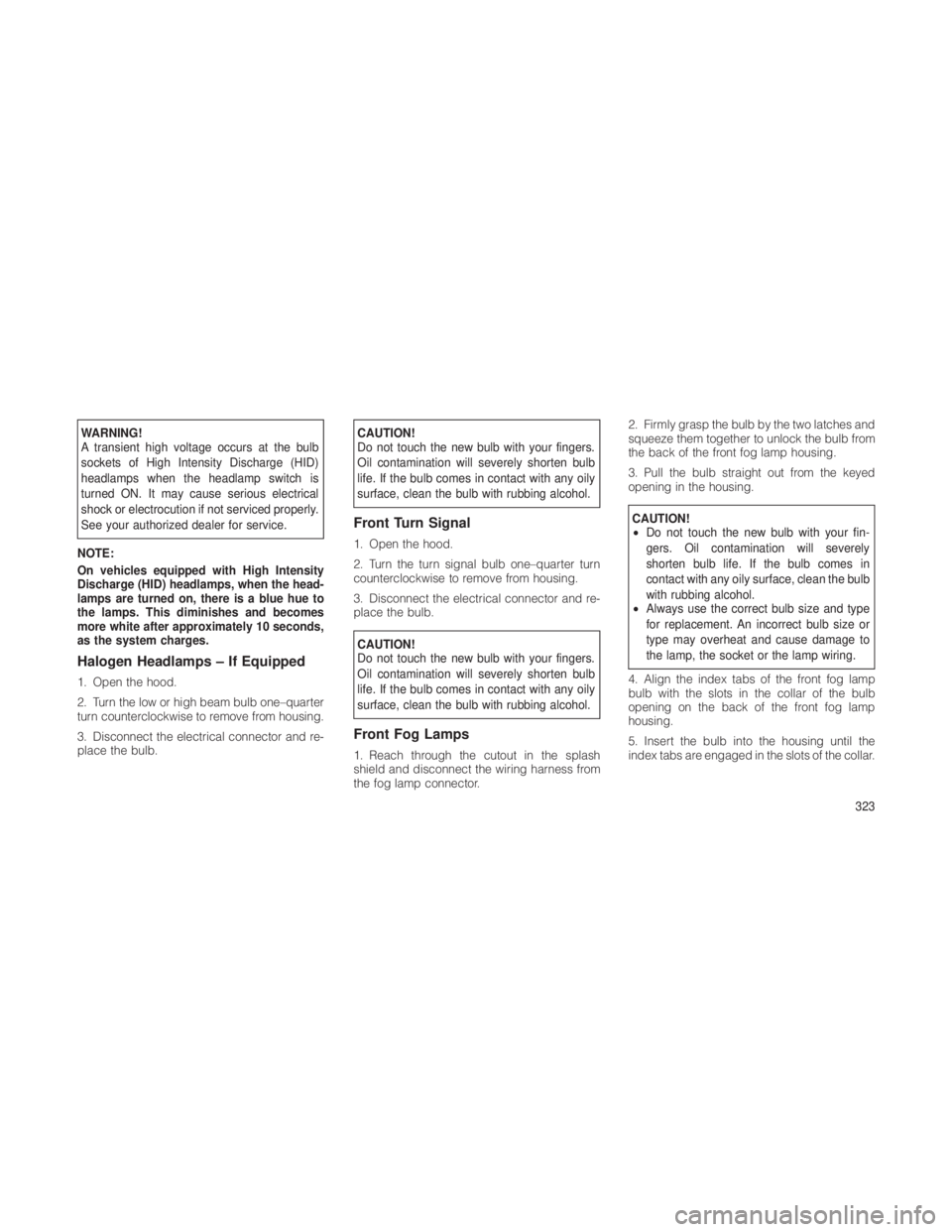
Halogen Headlamps – If Equipped
1. Open the hood.
2. Turn the low or high beam bulb one–quarter
turn counterclockwise to remove from housing.
3. Disconnect the electrical connector and re-
place the bulb.
CAUTION!
Do not touch the new bulb with your fingers.
Oil contamination will severely shorten bulb
life. If the bulb comes in contact with any oily
surface, clean the bulb with rubbing alcohol.
Front Turn Signal
1. Open the hood.
2. Turn the turn signal bulb one–quarter turn
counterclockwise to remove from housing.
3. Disconnect the electrical connector and re-
place the bulb.
CAUTION!
Do not touch the new bulb with your fingers.
Oil contamination will severely shorten bulb
life. If the bulb comes in contact with any oily
surface, clean the bulb with rubbing alcohol.
Front Fog Lamps
1. Reach through the cutout in the splash
shield and disconnect the wiring harness from
the fog lamp connector. 2. Firmly grasp the bulb by the two latches and
squeeze them together to unlock the bulb from
the back of the front fog lamp housing.
3. Pull the bulb straight out from the keyed
opening in the housing.
CAUTION!
•
Do not touch the new bulb with your fin-
gers. Oil contamination will severely
shorten bulb life. If the bulb comes in
contact with any oily surface, clean the bulb
with rubbing alcohol.
• Always use the correct bulb size and type
for replacement. An incorrect bulb size or
type may overheat and cause damage to
the lamp, the socket or the lamp wiring.
4. Align the index tabs of the front fog lamp
bulb with the slots in the collar of the bulb
opening on the back of the front fog lamp
housing.
5. Insert the bulb into the housing until the
index tabs are engaged in the slots of the collar.
323