brake sensor JEEP GRAND CHEROKEE 2012 Owner handbook (in English)
[x] Cancel search | Manufacturer: JEEP, Model Year: 2012, Model line: GRAND CHEROKEE, Model: JEEP GRAND CHEROKEE 2012Pages: 380, PDF Size: 3.21 MB
Page 121 of 380
NOTE:
The Electronic Speed Control system main-
tains speed up and down hills. A slight
speed change on moderate hills is normal.
On steep hills, a greater speed loss or gain may
occur so it may be preferable to drive without
Electronic Speed Control.
WARNING!
Electronic Speed Control can be dangerous
where the system cannot maintain a constant
speed. Your vehicle could go too fast for the
conditions, and you could lose control and
have an accident. Do not use Electronic
Speed Control in heavy traffic or on roads that
are winding, icy, snow-covered or slippery.
ADAPTIVE CRUISE CONTROL (ACC)
— IF EQUIPPED
Adaptive Cruise Control (ACC) increases the
driving convenience provided by cruise control
while traveling on highways and major road-
ways. However, it is not a safety system and not
designed to prevent collisions.
ACC will allow you to keep cruise control en-
gaged in light to moderate traffic conditions
without the constant need to reset your cruise
control. ACC utilizes a radar sensor designed
to detect a vehicle directly ahead of you.
NOTE:
•If the sensor does not detect a vehicle
ahead of you, ACC will maintain a fixed
set speed.
• If the ACC sensor detects a vehicle ahead,
ACC will apply limited braking or accel-
eration (not to exceed the original set
speed) automatically to maintain a preset
following distance, while matching the
speed of the vehicle ahead.
WARNING!
•Adaptive Cruise Control (ACC) is a conve-
nience system. It is not a substitute for
active driving involvement. It is always the
driver’s responsibility to be attentive of
road, traffic, and weather conditions, ve-
hicle speed, distance to the vehicle ahead;
and, most importantly, brake operation to
ensure safe operation of the vehicle under
all road conditions. Your complete attention
is always required while driving to maintain
safe control of your vehicle. Failure to fol-
low these warnings can result in a collision
and death or serious personal injury.
• The ACC system:
� Does not react to pedestrians, oncoming
vehicles, and stationary objects (e.g., a
stopped vehicle in a traffic jam or a
disabled vehicle).
� Cannot take street, traffic, and weather
conditions into account, and may be
limited upon adverse sight distance con-
ditions.
(Continued)11 7
Page 133 of 380
To Vary The Speed Setting
There are two ways to change the set speed:
•Use the accelerator pedal to adjust the ve-
hicle to the desired speed and press the SET
-button.
• Tap the RES +or SET -button to increase or
decrease the set speed in 0.6 mph (1 km/h)
increments respectively. Hold the RES +or
SET -button for 6 mph (10 km/h) increments.
To Cancel
The system will disable normal Cruise Control
without erasing the memory if:
• You softly tap or depress the brake pedal.
• You press the CANCEL button.
• The Electronic Stability Control/Traction Con-
trol System (ESC/TCS) activates.
To Resume
Press the RES +button and then remove your
foot from the accelerator pedal. The EVIC will
display the last set speed. To Turn Off
The system will turn off and erase the set speed
in memory if:
•
You push the ON/OFF button.
• You turn off the ignition.
• You engage Four-Wheel Drive Low.
If the Cruise Control system is turned off and
reactivated, the system will return to the last
driver setting (ACC or Normal Cruise Control).
Forward Collision Warning — If
Equipped
Forward Collision Warning (FCW) warns the
driver of a potential collision with the vehicle in
front of you and prompts the driver to take
action in order to avoid the collision.
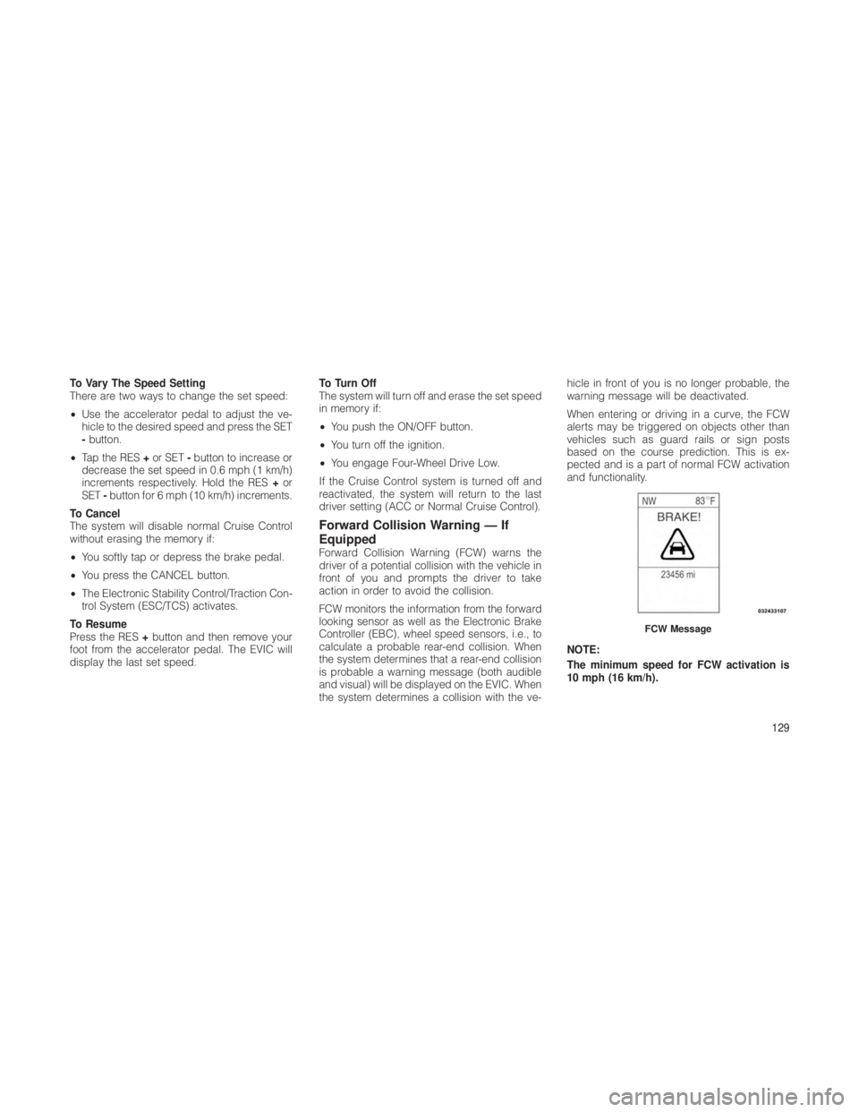
FCW monitors the information from the forward
looking sensor as well as the Electronic Brake
Controller (EBC), wheel speed sensors, i.e., to
calculate a probable rear-end collision. When
the system determines that a rear-end collision
is probable a warning message (both audible
and visual) will be displayed on the EVIC. When
the system determines a collision with the ve- hicle in front of you is no longer probable, the
warning message will be deactivated.
When entering or driving in a curve, the FCW
alerts may be triggered on objects other than
vehicles such as guard rails or sign posts
based on the course prediction. This is ex-
pected and is a part of normal FCW activation
and functionality.
NOTE:
The minimum speed for FCW activation is
10 mph (16 km/h).
FCW Message
129
Page 171 of 380
trol (ACC)” in “Understanding The Features
Of Your Vehicle” (if equipped).
• Distance Set — After changing the desired
following distance in the ACC system, this
message will display momentarily. Refer to
“Adaptive Cruise Control (ACC)” in “Under-
standing The Features Of Your Vehicle” (if
equipped).
• Brake — If the ACC system predicts that its
maximum braking level is not sufficient to
maintain the set distance, this message will
flash and a chime will sound while ACC
continues to apply its maximum braking ca-
pacity. When this occurs, you should imme-
diately apply the brakes as needed to main-
tain a safe distance from the vehicle ahead.
Refer to “Adaptive Cruise Control (ACC)” in
“Understanding The Features Of Your Ve-
hicle” (if equipped).
• Clean Radar Sensor in the Front of Vehicle —
If the ACC system deactivates due to perfor-
mance limiting conditions. Refer to “Adap-
tive Cruise Control (ACC)” in “Understanding
The Features Of Your Vehicle” (if equipped). •
ACC/FCW Unavailable Vehicle System Error
— If the ACC system turns off due to a
temporary malfunction that limits functional-
ity. Refer to “Adaptive Cruise Control (ACC)”
in “Understanding The Features Of Your Ve-
hicle” (if equipped).
• ACC/FCW Unavailable Service Radar Sen-
sor — If the ACC system turns off due to an
internal system fault that requires service
from an authorized dealer. Refer to “Adaptive
Cruise Control (ACC)” in “Understanding
The Features Of Your Vehicle” (if equipped).
• Coolant Low
• Service Air Suspension System
• Oil Change Due
• Key In Ignition
• Lights On
• Key In Ignition Lights On
• Ignition Or Accessory On
• Ignition Or Accessory On. Lights On
• Turn Signal On
• Park Assist On •
Warning Object Detected
• Memory 1 Profile Set
• Memory 2 Profile Set
• Memory System Unavailable — Not in Park
• Memory System Unavailable — Seatbelt
buckled
• Memory 1 Profile Recall
• Memory 2 Profile Recall
• Press Brake Pedal And Push Button To Start
• Wrong Key
• Damaged Key
• Key Not Programmed
• Function Currently Unavailable — Power Lift-
gate
• Unlock To Operate — Power Liftgate
• Put In Park To Operate — Power Liftgate
• Automatic High Beams On
• Automatic High Beams Off
• Service Four Wheel Drive System
167
Page 251 of 380
ERM can only reduce the chance of wheel lift
occurring during severe or evasive driving ma-
neuvers. It cannot prevent wheel lift due to
other factors such as road conditions, leaving
the roadway or striking objects or other ve-
hicles.
WARNING!
Many factors, such as vehicle loading, road
conditions and driving conditions, influence
the chance that wheel lift or rollover may
occur. ERM cannot prevent all wheel lift or
rollovers, especially those that involve leaving
the roadway or striking objects or other ve-
hicles. The capabilities of an ERM-equipped
vehicle must never be exploited in a reckless
or dangerous manner which could jeopardize
the user’s safety or the safety of others.
Electronic Stability Control (ESC)
This system enhances directional control and
stability of the vehicle under various driving
conditions. ESC corrects for oversteering or
understeering of the vehicle by applying the
brake of the appropriate wheel to assist incounteracting the oversteer or understeer con-
dition. Engine power may also be reduced to
help the vehicle maintain the desired path.
ESC uses sensors in the vehicle to determine
the vehicle path intended by the driver and
compares it to the actual path of the vehicle.
When the actual path does not match the
intended path, ESC applies the brake of the
appropriate wheel to assist in counteracting the
oversteer or understeer condition.
•
Oversteer - when the vehicle is turning more
than appropriate for the steering wheel po-
sition.
• Understeer - when the vehicle is turning less
than appropriate for the steering wheel po-
sition.
The “ESC Activation/Malfunction Indicator
Light” located in the instrument cluster will start
to flash as soon as the tires lose traction and
the ESC system becomes active. The “ESC
Activation/Malfunction Indicator Light” also
flashes when the TCS is active. If the “ESC
Activation/Malfunction Indicator Light” begins
to flash during acceleration, ease up on the
accelerator and apply as little throttle as pos- sible. Be sure to adapt your speed and driving
to the prevailing road conditions.
WARNING!
The Electronic Stability Control (ESC) cannot
prevent the natural laws of physics from act-
ing on the vehicle, nor can it increase the
traction afforded by prevailing road condi-
tions. ESC cannot prevent accidents, includ-
ing those resulting from excessive speed in
turns, driving on very slippery surfaces, or
hydroplaning. The capabilities of an ESC
equipped vehicle must never be exploited in a
reckless or dangerous manner which could
jeopardize the user’s safety or the safety of
others.
The ESC system has two available operating
modes in 4WD HIGH range, and one operating
mode in 4WD LOW range.
High Range (Four-Wheel Drive Models)
On
This is the normal operating mode for ESC in
4WD HIGH range. Whenever the vehicle is 247
Page 252 of 380
started or the transfer case (if equipped) is
shifted from 4WD LOW range or NEUTRAL
back to 4WD HIGH range, the ESC system will
be in this “On” mode. This mode should be
used for most driving situations. ESC should
only be turned to “Partial Off” mode for specific
reasons as noted below.
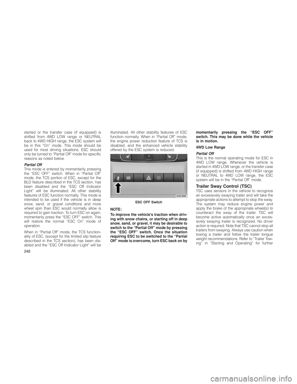
Partial Off
This mode is entered by momentarily pressing
the “ESC OFF” switch. When in “Partial Off”
mode, the TCS portion of ESC, except for the
BLD feature described in the TCS section, has
been disabled and the “ESC Off Indicator
Light” will be illuminated. All other stability
features of ESC function normally. This mode is
intended to be used if the vehicle is in deep
snow, sand, or gravel conditions and more
wheel spin than ESC would normally allow is
required to gain traction. To turn ESC on again,
momentarily press the “ESC OFF” switch. This
will restore the normal “ESC On” mode of
operation.
When in “Partial Off” mode, the TCS function-
ality of ESC, (except for the limited slip feature
described in the TCS section), has been dis-
abled and the “ESC Off Indicator Light” will beilluminated. All other stability features of ESC
function normally. When in “Partial Off” mode,
the engine power reduction feature of TCS is
disabled, and the enhanced vehicle stability
offered by the ESC system is reduced.
NOTE:
To improve the vehicle’s traction when driv-
ing with snow chains, or starting off in deep
snow, sand, or gravel, it may be desirable to
switch to the “Partial Off” mode by pressing
the “ESC OFF” switch. Once the situation
requiring ESC to be switched to the “Partial
Off” mode is overcome, turn ESC back on by
momentarily pressing the “ESC OFF”
switch. This may be done while the vehicle
is in motion.
4WD Low Range
Partial Off
This is the normal operating mode for ESC in
4WD LOW range. Whenever the vehicle is
started in 4WD LOW range, or the transfer case
(if equipped) is shifted from 4WD HIGH range
or NEUTRAL to 4WD LOW range, the ESC
system will be in the “Partial Off” mode.
Trailer Sway Control (TSC)TSC uses sensors in the vehicle to recognize
an excessively swaying trailer and will take the
appropriate actions to attempt to stop the sway.
The system may reduce engine power and
apply the brake of the appropriate wheel(s) to
counteract the sway of the trailer. TSC will
become active automatically once an exces-
sively swaying trailer is recognized. No driver
action is required. Note that TSC cannot stop all
trailers from swaying. Always use caution when
towing a trailer and follow the trailer tongue
weight recommendations. Refer to “Trailer Tow-
ing” in “Starting and Operating” for further
ESC OFF Switch
248
Page 325 of 380
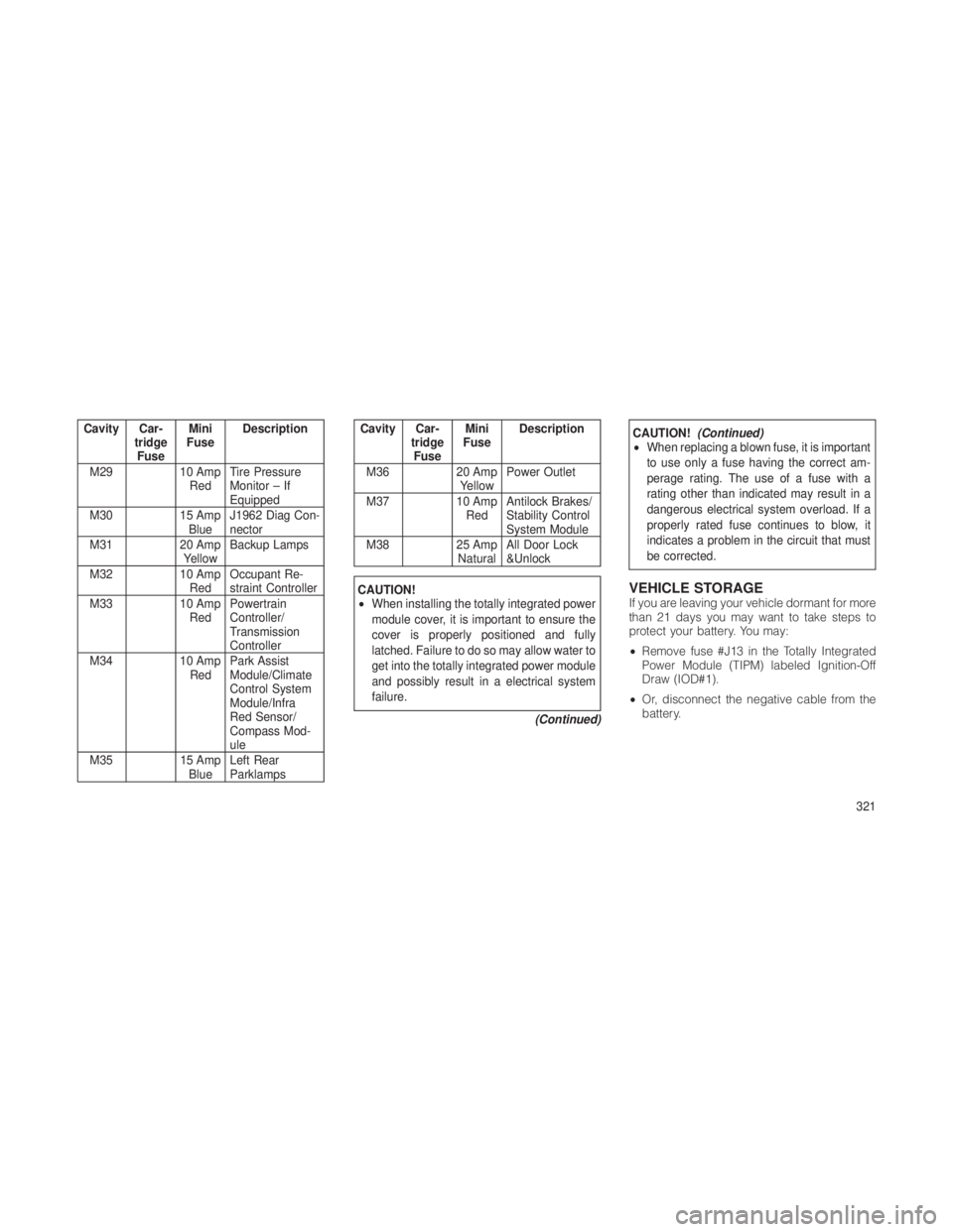
Cavity Car-tridgeFuse Mini
Fuse Description
M29 10 Amp RedTire Pressure
Monitor – If
Equipped
M30 15 Amp
Blue J1962 Diag Con-
nector
M31 20 Amp
Yellow Backup Lamps
M32 10 Amp
Red Occupant Re-
straint Controller
M33 10 Amp
Red Powertrain
Controller/
Transmission
Controller
M34 10 Amp
Red Park Assist
Module/Climate
Control System
Module/Infra
Red Sensor/
Compass Mod-
ule
M35 15 Amp
Blue Left Rear
ParklampsCavity Car-
tridgeFuse Mini
Fuse Description
M36 20 Amp YellowPower Outlet
M37 10 Amp RedAntilock Brakes/
Stability Control
System Module
M38 25 Amp
Natural All Door Lock
&Unlock
CAUTION!
•
When installing the totally integrated power
module cover, it is important to ensure the
cover is properly positioned and fully
latched. Failure to do so may allow water to
get into the totally integrated power module
and possibly result in a electrical system
failure.
(Continued)
CAUTION!(Continued)
• When replacing a blown fuse, it is important
to use only a fuse having the correct am-
perage rating. The use of a fuse with a
rating other than indicated may result in a
dangerous electrical system overload. If a
properly rated fuse continues to blow, it
indicates a problem in the circuit that must
be corrected.
VEHICLE STORAGEIf you are leaving your vehicle dormant for more
than 21 days you may want to take steps to
protect your battery. You may:
•Remove fuse #J13 in the Totally Integrated
Power Module (TIPM) labeled Ignition-Off
Draw (IOD#1).
• Or, disconnect the negative cable from the
battery.
321