sensor JEEP GRAND CHEROKEE 2013 Owner handbook (in English)
[x] Cancel search | Manufacturer: JEEP, Model Year: 2013, Model line: GRAND CHEROKEE, Model: JEEP GRAND CHEROKEE 2013Pages: 408, PDF Size: 3.21 MB
Page 70 of 408
•ELECTRONIC SPEED CONTROL — IF EQUIPPED ...........117•To Activate ..................................117
• To Set A Desired Speed ..........................118
• To Deactivate .................................118
• To Resume Speed ..............................118
• To Vary The Speed Setting .........................118
• To Accelerate For Passing .........................118
•ADAPTIVE CRUISE CONTROL (ACC) — IF EQUIPPED ........119•Adaptive Cruise Control (ACC) Operation ................120
• Activating Adaptive Cruise Control (ACC) ................121
• To Activate ................................. .121
• To Set A Desired ACC Speed ...................... .121
• To Cancel .................................. .122
• ToTurnOff................................. .122
• To Resume Speed ............................. .123
• To Vary The Speed Setting ........................ .123
• Setting The Following Distance In ACC .................124
• Adaptive Cruise Control (ACC) Menu ..................125
• Display Warnings And Maintenance ...................126
• Precautions While Driving With ACC ...................128
• General Information ........................... .130
• Normal (Fixed Speed) Cruise Control Mode ...............130
• Forward Collision Warning — If Equipped ...............131
•PARKSENSE® FRONT AND REAR PARK ASSIST — IF
EQUIPPED ...................................134
•ParkSense® Sensors ........................... .134
• ParkSense® Warning Display ...................... .134
66
Page 123 of 408

ADAPTIVE CRUISE CONTROL
(ACC) — IF EQUIPPED
Adaptive Cruise Control (ACC) increases the
driving convenience provided by cruise control
while traveling on highways and major road-
ways. However, it is not a safety system and not
designed to prevent collisions.
ACC will allow you to keep cruise control en-
gaged in light to moderate traffic conditions
without the constant need to reset your cruise
control. ACC utilizes a radar sensor and a
forward facing camera designed to detect a
vehicle directly ahead of you.
NOTE:
•If the sensor does not detect a vehicle
ahead of you, ACC will maintain a fixed
set speed.
• If the ACC sensor detects a vehicle ahead,
ACC will apply limited braking or accel-
eration (not to exceed the original set
speed) automatically to maintain a preset
following distance, while matching the
speed of the vehicle ahead.
WARNING!
•Adaptive Cruise Control (ACC) is a conve-
nience system. It is not a substitute for
active driving involvement. It is always the
driver’s responsibility to be attentive of
road, traffic, and weather conditions, ve-
hicle speed, distance to the vehicle ahead;
and, most importantly, brake operation to
ensure safe operation of the vehicle under
all road conditions. Your complete atten-
tion is always required while driving to
maintain safe control of your vehicle. Fail-
ure to follow these warnings can result in a
collision and death or serious personal
injury.
• The ACC system:
• Does not react to pedestrians, on-
coming vehicles, and stationary ob-
jects (e.g., a stopped vehicle in a
traffic jam or a disabled vehicle).
(Continued)
WARNING!(Continued)
•Cannot take street, traffic, and
weather conditions into account, and
may be limited upon adverse sight
distance conditions.
• Does not always fully recognize com-
plex driving conditions, which can
result in wrong or missing distance
warnings.
• Can only apply a maximum of 40% of
the vehicle’s braking capability, and
will not bring the vehicle to a com-
plete stop.
11 9
Page 128 of 408
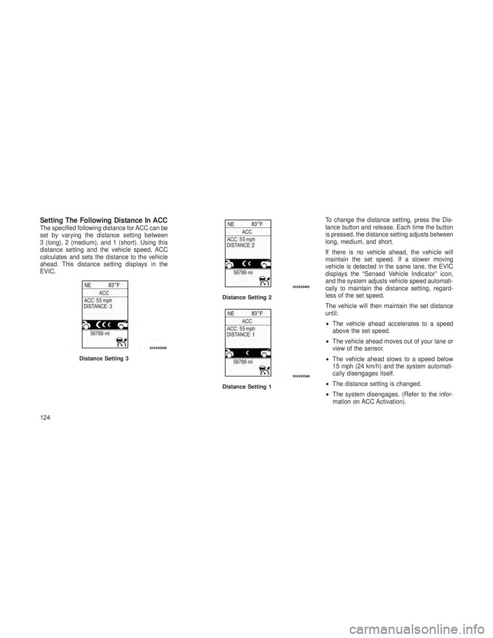
Setting The Following Distance In ACCThe specified following distance for ACC can be
set by varying the distance setting between
3 (long), 2 (medium), and 1 (short). Using this
distance setting and the vehicle speed, ACC
calculates and sets the distance to the vehicle
ahead. This distance setting displays in the
EVIC.To change the distance setting, press the Dis-
tance button and release. Each time the button
is pressed, the distance setting adjusts between
long, medium, and short.
If there is no vehicle ahead, the vehicle will
maintain the set speed. If a slower moving
vehicle is detected in the same lane, the EVIC
displays the “Sensed Vehicle Indicator” icon,
and the system adjusts vehicle speed automati-
cally to maintain the distance setting, regard-
less of the set speed.
The vehicle will then maintain the set distance
until:
•
The vehicle ahead accelerates to a speed
above the set speed.
• The vehicle ahead moves out of your lane or
view of the sensor.
• The vehicle ahead slows to a speed below
15 mph (24 km/h) and the system automati-
cally disengages itself.
• The distance setting is changed.
• The system disengages. (Refer to the infor-
mation on ACC Activation).
Distance Setting 3
Distance Setting 2
Distance Setting 1
124
Page 130 of 408
The ACC screen will display once again if any
ACC activity occurs, which may include any of
the following:
•Set Speed Change
• Distance Setting Change
• System Cancel
• Driver Override
• System Off
• ACC Proximity Warning
• ACC Unavailable Warning
• The EVIC will return to the last display se-
lected after five seconds of no ACC display
activity.
Display Warnings And Maintenance
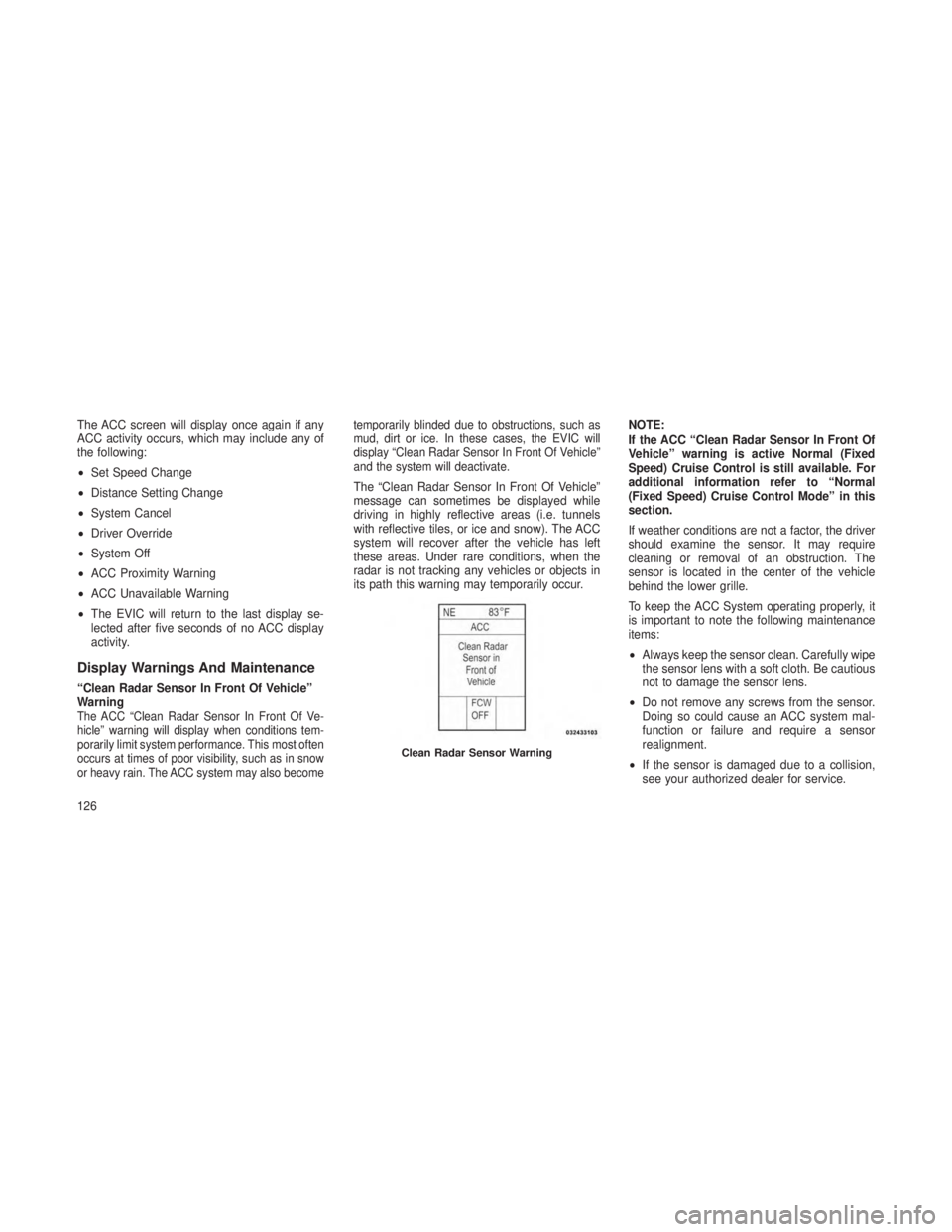
“Clean Radar Sensor In Front Of Vehicle”
Warning
The ACC “Clean Radar Sensor In Front Of Ve-
hicle” warning will display when conditions tem-
porarily limit system performance. This most often
occurs at times of poor visibility, such as in snow
or heavy rain. The ACC system may also become temporarily blinded due to obstructions, such as
mud, dirt or ice. In these cases, the EVIC will
display “Clean Radar Sensor In Front Of Vehicle”
and the system will deactivate.
The “Clean Radar Sensor In Front Of Vehicle”
message can sometimes be displayed while
driving in highly reflective areas (i.e. tunnels
with reflective tiles, or ice and snow). The ACC
system will recover after the vehicle has left
these areas. Under rare conditions, when the
radar is not tracking any vehicles or objects in
its path this warning may temporarily occur.
NOTE:
If the ACC “Clean Radar Sensor In Front Of
Vehicle” warning is active Normal (Fixed
Speed) Cruise Control is still available. For
additional information refer to “Normal
(Fixed Speed) Cruise Control Mode” in this
section.
If weather conditions are not a factor, the driver
should examine the sensor. It may require
cleaning or removal of an obstruction. The
sensor is located in the center of the vehicle
behind the lower grille.
To keep the ACC System operating properly, it
is important to note the following maintenance
items:
•
Always keep the sensor clean. Carefully wipe
the sensor lens with a soft cloth. Be cautious
not to damage the sensor lens.
• Do not remove any screws from the sensor.
Doing so could cause an ACC system mal-
function or failure and require a sensor
realignment.
• If the sensor is damaged due to a collision,
see your authorized dealer for service.
Clean Radar Sensor Warning
126
Page 131 of 408

•Do not attach or install any accessories near
the sensor, including transparent material or
aftermarket grilles. Doing so could cause an
ACC system failure or malfunction.
When the condition that deactivated the system
is no longer present, the system will return to
the “Adaptive Cruise Control Off” state and will
resume function by simply reactivating it.
NOTE:
• If the “Clean Radar Sensor In Front Of
Vehicle” message occurs frequently
(e.g. more than once on every trip) with-
out any snow, rain, mud, or other obstruc-
tion, have the radar sensor realigned at
your authorized dealer.
•
Installing a snow plow, front-end protector,
an aftermarket grille or modifying the grille
is not recommended. Doing so may block
the sensor and inhibit ACC operation.
Removing ACC Sensor For Off-Roading
NOTE:
When off-roading, it may be advisable to
remove the ACC sensor. The sensor is lo-
cated behind the front lower grille in the
center of the vehicle. After removing the
lower fascia, you may remove the lower
sensor and bracket assembly.
To remove the sensor follow these instructions:
1. Unplug the connector by depressing the two
tabs on the connector and pulling it out. Do not
pull by the wiring or use any tools to remove the
connector.
2. Remove the wiring christmas tree attach-
ment from the back of the bracket.
3. Remove the two M6 fasteners that connect
the bracket to the bumper.
NOTE:
Do not change the adjustment fasteners or
pull the sensor off of the bracket. Doing so
may misalign the sensor. Store the sensor and bracket assembly in a
safe location. The wiring and connector must be
stowed properly after the sensor and bracket
assembly is removed.
A connector plug is stowed on top of the bumper
beam. Insert the wiring connector into the con-
nector plug.
NOTE:
When the sensor is removed, Adaptive Cruise
Control, Normal Cruise Control, and Forward
Collision Warning will not be available. The
cluster will display the warning “ACC/FCW
Unavailable - Service Radar Sensor.”
To reinstall the sensor and bracket assembly
reverse the process above. The fastener torque
required to assembly the bracket back to the
beam is 6.6 ft lbs (9 N·m).
127
Page 135 of 408
To Vary The Speed Setting
There are two ways to change the set speed:
•
Use the accelerator pedal to adjust the vehicle
to the desired speed and press the SET-
button.
•Tap the RES +or SET -button to increase or
decrease the set speed in 1 mph (1.6 km/h)
increments respectively. Hold the RES +or
SET -button for 5 mph (8 km/h) increments.
To Cancel
The system will disable normal Cruise Control
without erasing the memory if:
• You softly tap or depress the brake pedal.
• You press the CANCEL button.
• The Electronic Stability Control/Traction Con-
trol System (ESC/TCS) activates.
To Resume
Press the RES +button and then remove your
foot from the accelerator pedal. The EVIC will
display the last set speed. To Turn Off
The system will turn off and erase the set speed
in memory if:
•
You push the Normal Fixed Speed ON/OFF
button.
• You turn off the ignition.
• You engage Four-Wheel Drive Low.
Forward Collision Warning — If
Equipped
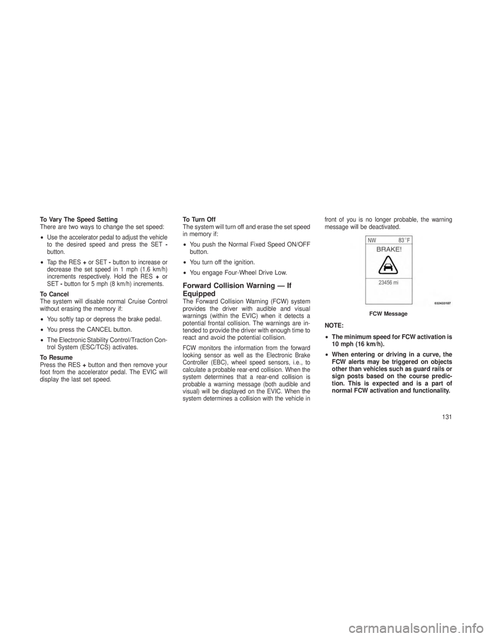
The Forward Collision Warning (FCW) system
provides the driver with audible and visual
warnings (within the EVIC) when it detects a
potential frontal collision. The warnings are in-
tended to provide the driver with enough time to
react and avoid the potential collision.
FCW monitors the information from the forward
looking sensor as well as the Electronic Brake
Controller (EBC), wheel speed sensors, i.e., to
calculate a probable rear-end collision. When the
system determines that a rear-end collision is
probable a warning message (both audible and
visual) will be displayed on the EVIC. When the
system determines a collision with the vehicle in front of you is no longer probable, the warning
message will be deactivated.
NOTE:
•
The minimum speed for FCW activation is
10 mph (16 km/h).
• When entering or driving in a curve, the
FCW alerts may be triggered on objects
other than vehicles such as guard rails or
sign posts based on the course predic-
tion. This is expected and is a part of
normal FCW activation and functionality.
FCW Message
131
Page 138 of 408
PARKSENSE® FRONT AND
REAR PARK ASSIST — IF
EQUIPPED
The ParkSense® Park Assist system provides
visual and audible indications of the distance
between the rear and/or front fascia and a
detected obstacle when backing up or moving
forward, e.g. during a parking maneuver. Refer
to ParkSense® System Usage Precautions for
limitations of this system and recommenda-
tions.
ParkSense® will retain the last system state
(enabled or disabled) from the last ignition cycle
when the ignition is changed to the ON/RUN
position.
ParkSense® can be active only when the shift
lever is in REVERSE or DRIVE. If ParkSense®
is enabled at one of these shift lever positions,
the system will remain active until the vehicle
speed is increased to approximately 7 mph
(11 km/h) or above. The system will become
active again if the vehicle speed is decreased to
speeds less than approximately 6 mph (9 km/h).
ParkSense® SensorsThe four ParkSense® sensors, located in the
rear fascia/bumper, monitor the area behind the
vehicle that is within the sensors’ field of view.
The sensors can detect obstacles from approxi-
mately 12 in (30 cm) up to 59 in (150 cm) from
the rear fascia/bumper in the horizontal direc-
tion, depending on the location, type and orien-
tation of the obstacle.
The six ParkSense® sensors, located in the
front fascia/bumper, monitor the area in front of
the vehicle that is within the sensors’ field of
view. The sensors can detect obstacles from
approximately 12 in (30 cm) up to 47 in (120 cm)
from the front fascia/bumper in the horizontal
direction, depending on the location, type and
orientation of the obstacle.
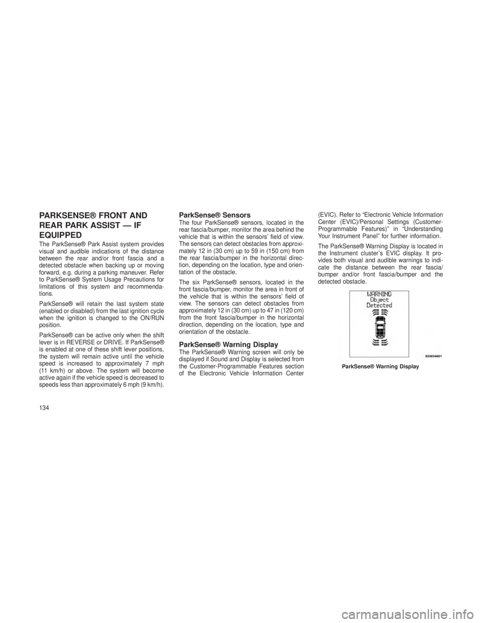
ParkSense® Warning DisplayThe ParkSense® Warning screen will only be
displayed if Sound and Display is selected from
the Customer-Programmable Features section
of the Electronic Vehicle Information Center(EVIC). Refer to “Electronic Vehicle Information
Center (EVIC)/Personal Settings (Customer-
Programmable Features)” in “Understanding
Your Instrument Panel” for further information.
The ParkSense® Warning Display is located in
the Instrument cluster’s EVIC display. It pro-
vides both visual and audible warnings to indi-
cate the distance between the rear fascia/
bumper and/or front fascia/bumper and the
detected obstacle.
ParkSense® Warning Display
134
Page 141 of 408

Service The ParkSense® Park Assist
System
When the ParkSense Park Assist System is
malfunctioning, the instrument cluster will actu-
ate a single chime, once per ignition cycle, and
it will display the “CLEAN PARK ASSIST SEN-
SORS” or the “SERVICE PARK ASSIST SYS-
TEM” message. The instrument cluster will dis-
play the “CLEAN PARK ASSIST SENSORS”
message when any of the rear or front sensors
are blocked by snow, mud, or ice. The instru-
ment cluster will display the “SERVICE PARK
ASSIST SYSTEM” message when any of the
rear or front sensors are damaged and require
service.
When the shift lever is moved to REVERSE or
DRIVE and the system has detected a faulted
condition, the EVIC will display the “CLEAN
PARK ASSIST SENSORS” or the “SERVICE
PARK ASSIST SYSTEM” message for appro-
priately five seconds. Then, when the shift lever
is moved to REVERSE, the EVIC will display
the “PARK ASSIST SYSTEM OFF” message foras long as the vehicle is in REVERSE. Under
this condition ParkSense will not operate. Refer
to “Electronic Vehicle Information Center
(EVIC)” in “Understanding Your Instrument
Panel” for further information.
If the “CLEAN PARK ASSIST SENSORS” mes-
sage appears in the Electronic Vehicle Informa-
tion Center (EVIC) make sure the outer surface
and the underside of the rear fascia/bumper
and/or front fascia/bumper is clean and clear of
snow, ice, mud, dirt or other obstruction and
then cycle the ignition. If the message continues
to appear, see an authorized dealer.
If the “SERVICE PARK ASSIST SYSTEM” mes-
sage appears in the EVIC, see an authorized
dealer.
Cleaning The ParkSense® SystemClean the ParkSense® sensors with water, car
wash soap and a soft cloth. Do not use rough or
hard cloths. Do not scratch or poke the sensors.
Otherwise, you could damage the sensors.
ParkSense® System Usage
Precautions
NOTE:
•
Ensure that the front and rear bumper are
free of snow, ice, mud, dirt and debris to
keep the ParkSense® system operating
properly.
• Jackhammers, large trucks, and other vi-
brations could affect the performance of
ParkSense®.
• When you turn ParkSense® off, the in-
strument cluster will display “PARK AS-
SIST SYSTEM OFF.” Furthermore, once
you turn ParkSense® off, it remains off
until you turn it on again, even if you cycle
the ignition key.
• When you move the shift lever to the
REVERSE position and ParkSense is
turned off, the instrument cluster will dis-
play “PARK ASSIST SYSTEM OFF” mes-
sage for as long as the vehicle is in
REVERSE.
137
Page 142 of 408

•ParkSense®, when on, will MUTE the ra-
dio when it is sounding a tone.
• Clean the ParkSense® sensors regularly,
taking care not to scratch or damage
them. The sensors must not be covered
with ice, snow, slush, mud, dirt or debris.
Failure to do so can result in the system
not working properly. The ParkSense®
system might not detect an obstacle be-
hind or in front of the fascia/bumper, or it
could provide a false indication that an
obstacle is behind or in front of the
fascia/bumper.
•
Objects such as bicycle carriers, trailer
hitches, etc., must not be placed within
12 in (30 cm) from the rear fascia/bumper
while driving the vehicle. Failure to do so
can result in the system misinterpreting a
close object as a sensor problem, causing
the “SERVICE PARK ASSIST SYSTEM”
message to be displayed in the instrument
cluster.
• On vehicles equipped with a tailgate,
ParkSense® should be disabled when the
tailgate is in the lowered or open position.
A lowered tailgate could provide a false
indication that an obstacle is behind the
vehicle.
CAUTION!
•ParkSense® is only a parking aid and it is
unable to recognize every obstacle, includ-
ing small obstacles. Parking curbs might
be temporarily detected or not detected at
all. Obstacles located above or below the
sensors will not be detected when they are
in close proximity.
• The vehicle must be driven slowly when
using ParkSense® in order to be able to
stop in time when an obstacle is detected.
When backing up, it is recommended that
the driver looks over his/her shoulder
when using ParkSense®.
WARNING!
•Drivers must be careful when backing up
even when using the ParkSense® Park
Assist system. Always check carefully be-
hind your vehicle, look behind you, and be
sure to check for pedestrians, animals,
other vehicles, obstructions, and blind
spots before backing up. You are respon-
sible for safety and must continue to pay
attention to your surroundings. Failure to
do so can result in serious injury or death.
• Before using the ParkSense® Park Assist
system, it is strongly recommended that
the ball mount and hitch ball assembly is
disconnected from the vehicle when the
vehicle is not used for towing. Failure to do
so can result in injury or damage to ve-
hicles or obstacles because the hitch ball
will be much closer to the obstacle than the
rear fascia when the warning display turns
on the single flashing arc and sounds the
continuous tone. Also, the sensors could
(Continued)
138
Page 168 of 408
10. Electronic Vehicle Information Center
(EVIC) Display/Odometer Display
The odometer display shows the total distance
the vehicle has been driven.
The Electronic Vehicle Information Center
(EVIC). Refer to “Electronic Vehicle Information
Center”.
11. Tire Pressure Monitoring Telltale LightEach tire, including the spare (if
provided), should be checked
monthly when cold and inflated
to the inflation pressure recom-
mended by the vehicle manufac-
turer on the vehicle placard or tire inflation
pressure label. (If your vehicle has tires of a
different size than the size indicated on the
vehicle placard or tire inflation pressure label,
you should determine the proper tire inflation
pressure for those tires.)
As an added safety feature, your vehicle has
been equipped with a Tire Pressure Monitoring
System (TPMS) that illuminates a low tire pres-
sure telltale when one or more of your tires is
significantly under-inflated. Accordingly, when the low tire pressure telltale illuminates, you
should stop and check your tires as soon as
possible, and inflate them to the proper pres-
sure. Driving on a significantly under-inflated
tire causes the tire to overheat and can lead to
tire failure. Under-inflation also reduces fuel
efficiency and tire tread life, and may affect the
vehicle’s handling and stopping ability.
Please note that the TPMS is not a substitute for
proper tire maintenance, and it is the driver’s
responsibility to maintain correct tire pressure,
even if under-inflation has not reached the level
to trigger illumination of the TPMS low tire
pressure telltale.
Your vehicle has also been equipped with a
TPMS malfunction indicator to indicate when
the system is not operating properly. The TPMS
malfunction indicator is combined with the low
tire pressure telltale. When the system detects
a malfunction, the telltale will flash for approxi-
mately one minute and then remain continu-
ously illuminated. This sequence will continue
upon subsequent vehicle start-ups as long as
the malfunction exists. When the malfunction
indicator is illuminated, the system may not be
able to detect or signal low tire pressure as
intended. TPMS malfunctions may occur for a
variety of reasons, including the installation of
replacement or alternate tires or wheels on the
vehicle that prevent the TPMS from functioning
properly. Always check the TPMS malfunction
telltale after replacing one or more tires or
wheels on your vehicle, to ensure that the
replacement or alternate tires and wheels allow
the TPMS to continue to function properly.
CAUTION!
The TPMS has been optimized for the origi-
nal equipment tires and wheels. TPMS pres-
sures and warning have been established for
the tire size equipped on your vehicle. Un-
desirable system operation or sensor dam-
age may result when using replacement
equipment that is not of the same size, type,
and/or style. Aftermarket wheels can cause
sensor damage. Do not use tire sealant from
a can or balance beads if your vehicle is
equipped with a TPMS, as damage to the
sensors may result.
164