JEEP GRAND CHEROKEE 2013 Owner handbook (in English)
Manufacturer: JEEP, Model Year: 2013, Model line: GRAND CHEROKEE, Model: JEEP GRAND CHEROKEE 2013Pages: 408, PDF Size: 3.21 MB
Page 331 of 408
Special AdditivesThe manufacturer strongly recommends against
using any special additives in the transmission.
Automatic Transmission Fluid (ATF) is an engi-
neered product and its performance may be
impaired by supplemental additives. Therefore,
do not add any fluid additives to the transmis-
sion. The only exception to this policy is the use
of special dyes for diagnosing fluid leaks. Avoid
using transmission sealers as they may ad-
versely affect seals.
CAUTION!
Do not use chemical flushes in your trans-
mission as the chemicals can damage your
transmission components. Such damage is
not covered by the New Vehicle Limited
Warranty.Fluid Level Check – 3.6L And 3.0L Diesel
Engine
The fluid level is preset at the factory and does
not require adjustment under normal operating
conditions. Routine fluid level checks are not
required, therefore the transmission has no
dipstick. Your authorized dealer can check your
transmission fluid level using a special service
dipstick.
If you notice fluid leakage or transmission mal-
function, visit your authorized dealer immedi-
ately to have the transmission fluid level
checked. Operating the vehicle with an im-
proper fluid level can cause severe transmis-
sion damage.
CAUTION!
•
If a transmission fluid leak occurs, visit
your authorized dealer immediately. Se-
vere transmission damage may occur.
Your authorized dealer has the proper
tools to adjust the fluid level accurately. Fluid Level Check – 5.7L Engine
It is best to check the fluid level when the
transmission is at normal operating temperature
(approximately 180°F / 82°C). This occurs after
at least 15 miles (25 km) of driving. At normal
operating temperature the fluid cannot be held
comfortably between the fingertips.
Use the following procedure to check the fluid
level properly:
1. Park the vehicle on level ground.
2. Run the engine at idle speed and normal
operating temperature.
3. Fully apply the parking brake, and press the
brake pedal.
4. Place the shift lever momentarily into each
gear position (allowing time for the transmission
to fully engage in each position), ending with the
shift lever in PARK.
5. Remove the dipstick, wipe it clean and rein-
sert it until seated.
327
Page 332 of 408
6.Remove the dipstick again, and note the fluid
level on both sides. The fluid level reading is only
valid if there is a solid coating of oil on both sides of
the dipstick. The holes in the dipstick will be full of
fluid if the actual level is at or above the hole. The
fluid level should be between the "HOT"(upper)
reference holes on the dipstick at normal operating
temperature. If the fluid level is low, add fluid
through the dipstick tube to bring it to the proper
level. Do not overfill. Use ONLY the recom-
mended fluid (see "Fluids, Lubricants, and Genuine
Parts" for fluid specifications). After adding any
quantity of oil through the dipstick tube, wait a
minimum of two minutes for the oil to fully drain into
the transmission before rechecking the fluid level.
NOTE:If it is necessary to check the transmission
below the operating temperature, the fluid level
should be between the two “COLD” (lower)
holes on the dipstick with the fluid at approxi-
mately 70°F (21°C) (room temperature). If the
fluid level is correctly established at room tem-
perature, it should be between the “HOT” (up-
per) reference holes when the transmission
reaches 180°F (82°C). Remember it is best to
check the level at the normal operating tem-
perature.
CAUTION!
If the fluid temperature is below 50°F (10°C)
it may not register on the dipstick. Do not add
fluid until the temperature is elevated enough
to produce an accurate reading. Run the
engine at idle, in PARK, to warm the fluid.
7. Check for leaks. Release the parking brake.
NOTE:
To prevent dirt and water from entering the
transmission after checking or replenishing
fluid, make sure that the dipstick cap is
properly reseated. It is normal for the dip-
stick cap to spring back slightly from its
fully seated position, as long as its seal
remains engaged in the dipstick tube.
Fluid And Filter Changes
Refer to the “Maintenance Schedule” for the
proper maintenance intervals.
In addition, change the fluid and filter if the
transmission is disassembled for any reason.Appearance Care And Protection
From Corrosion
Protection Of Body And Paint From CorrosionVehicle body care requirements vary according
to geographic locations and usage. Chemicals
that make roads passable in snow and ice, and
those that are sprayed on trees and road sur-
faces during other seasons, are highly corrosive
to the metal in your vehicle.
The following maintenance recommendations
will enable you to obtain maximum benefit from
the corrosion resistance built into your vehicle.
What Causes Corrosion?
Corrosion is the result of deterioration or re-
moval of paint and protective coatings from your
vehicle.
The most common causes are:
• Road salt, dirt and moisture accumulation.
• Stone and gravel impact.
• Insects, tree sap and tar.
• Salt in the air near seacoast localities.
• Atmospheric fallout/industrial pollutants.
328
Page 333 of 408
Washing
•Wash your vehicle regularly. Always wash
your vehicle in the shade using MOPAR®
Car Wash, or a mild car wash soap, and rinse
the panels completely with clear water.
•
If insects, tar, or other similar deposits have
accumulated on your vehicle, use MOPAR®
Super Kleen Bug and Tar Remover to remove.
• Use a high quality cleaner wax, such as
MOPAR® Cleaner Wax to remove road film,
stains and to protect your paint finish. Take
care never to scratch the paint.
• Avoid using abrasive compounds and power
buffing that may diminish the gloss or thin out
the paint finish.
CAUTION!
•Do not use abrasive or strong cleaning
materials such as steel wool or scouring
powder that will scratch metal and painted
surfaces.
(Continued)
CAUTION!(Continued)
•Use of power washers exceeding 1,200 psi
(8 274 kPa) can result in damage or removal
of paint and decals.
Special Care
• If you drive on salted or dusty roads or if you
drive near the ocean, hose off the undercar-
riage at least once a month.
• It is important that the drain holes in the lower
edges of the doors, rocker panels, and trunk
be kept clear and open.
• If you detect any stone chips or scratches in
the paint, touch them up immediately. The
cost of such repairs is considered the re-
sponsibility of the owner.
• If your vehicle is damaged due to a collision
or similar cause that destroys the paint and
protective coating, have your vehicle re-
paired as soon as possible. The cost of such
repairs is considered the responsibility of the
owner. •
If you carry special cargo such as chemicals,
fertilizers, de-icer salt, etc., be sure that such
materials are well packaged and sealed.
• If a lot of driving is done on gravel roads,
consider mud or stone shields behind each
wheel.
• Use MOPAR® Touch Up Paint on scratches
as soon as possible. Your authorized dealer
has touch up paint to match the color of your
vehicle.
Wheel And Wheel Trim Care
• All wheels and wheel trim, especially alumi-
num and chrome plated wheels, should be
cleaned regularly with a mild soap and water
to prevent corrosion.
• To remove heavy soil and/or excessive brake
dust, use MOPAR® Wheel Cleaner.
329
Page 334 of 408
CAUTION!
Do not use scouring pads, steel wool, a
bristle brush, or metal polishes. Do not use
oven cleaner. These products may damage
the wheel’s protective finish. Avoid automatic
car washes that use acidic solutions or harsh
brushes that may damage the wheel’s pro-
tective finish. Only MOPAR® Wheel Cleaner
or equivalent is recommended.
Stain Repel Fabric Cleaning Procedure – If
Equipped
Stain Repel seats may be cleaned in the follow-
ing manner:
• Remove as much of the stain as possible by
blotting with a clean, dry towel.
• Blot any remaining stain with a clean, damp
towel.
• For tough stains, apply MOPAR® Total
Clean, or a mild soap solution to a clean,
damp cloth and remove stain. Use a fresh,
damp towel to remove soap residue. •
For grease stains, apply MOPAR® Multi-
Purpose Cleaner to a clean, damp cloth and
remove stain. Use a fresh, damp towel to
remove soap residue.
•
Do not use any harsh solvents or any other
form of protectants on Stain Repel products.
Interior Care
Use MOPAR® Total Clean to clean fabric uphol-
stery and carpeting.
Use MOPAR® Total Clean to clean vinyl uphol-
stery.
MOPAR® Total Clean is specifically recom-
mended for leather upholstery.
Your leather upholstery can be best preserved by
regular cleaning with a damp soft cloth. Small
particles of dirt can act as an abrasive and
damage the leather upholstery and should be
removed promptly with a damp cloth. Stubborn
soils can be removed easily with a soft cloth and
MOPAR® Total Clean. Care should be taken to
avoid soaking your leather upholstery with any
liquid. Please do not use polishes, oils, cleaning
fluids, solvents, detergents, or ammonia-based
cleaners to clean your leather upholstery. Appli- cation of a leather conditioner is not required to
maintain the original condition.
WARNING!
Do not use volatile solvents for cleaning
purposes. Many are potentially flammable,
and if used in closed areas they may cause
respiratory harm.
Cleaning Headlights
Your vehicle has plastic headlights that are
lighter and less susceptible to stone breakage
than glass headlights.
Plastic is not as scratch resistant as glass and
therefore different lens cleaning procedures
must be followed.
To minimize the possibility of scratching the
lenses and reducing light output, avoid wiping
with a dry cloth. To remove road dirt, wash with
a mild soap solution followed by rinsing.
Do not use abrasive cleaning components, sol-
vents, steel wool or other aggressive material to
clean the lenses.
330
Page 335 of 408
Glass Surfaces
All glass surfaces should be cleaned on a
regular basis with MOPAR® Glass Cleaner, or
any commercial household-type glass cleaner.
Never use an abrasive type cleaner. Use cau-
tion when cleaning the inside rear window
equipped with electric defrosters or the right
rear quarter window equipped with the radio
antenna. Do not use scrapers or other sharp
instrument that may scratch the elements.
When cleaning the rear view mirror, spray
cleaner on the towel or rag that you are using.
Do not spray cleaner directly on the mirror.
Cleaning Plastic Instrument Cluster Lenses
The lenses in front of the instruments in this
vehicle are molded in clear plastic. When clean-
ing the lenses, care must be taken to avoid
scratching the plastic.
1. Clean with a wet soft rag. A mild soap
solution may be used, but do not use high
alcohol content or abrasive cleaners. If soap is
used, wipe clean with a clean damp rag.
2. Dry with a soft cloth.Seat Belt Maintenance
Do not bleach, dye or clean the belts with
chemical solvents or abrasive cleaners. This will
weaken the fabric. Sun damage can also
weaken the fabric.
If the belts need cleaning, use a mild soap
solution or lukewarm water. Do not remove the
belts from the car to wash them. Dry with a soft
cloth.
Replace the belts if they appear frayed or worn
or if the buckles do not work properly.
FUSES
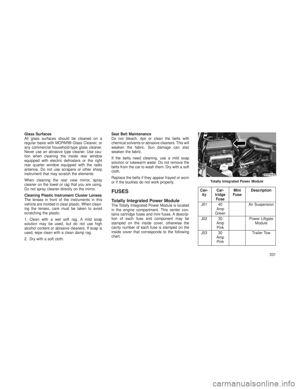
Totally Integrated Power ModuleThe Totally Integrated Power Module is located
in the engine compartment. This center con-
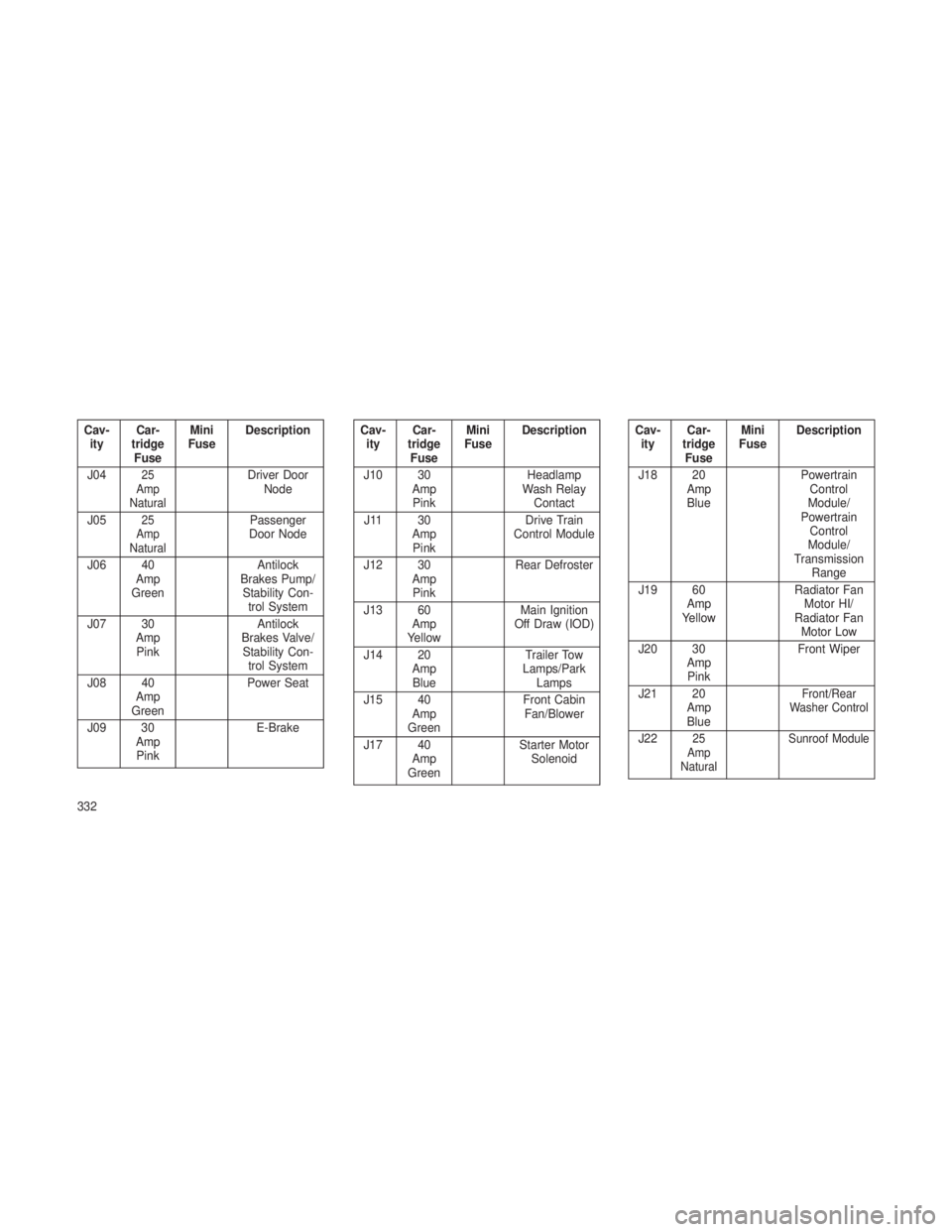
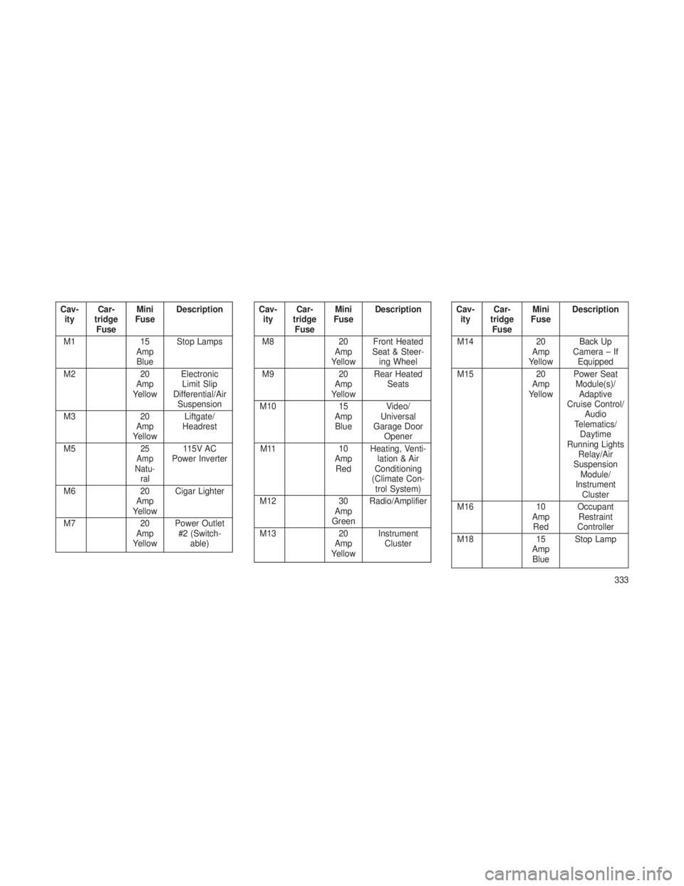
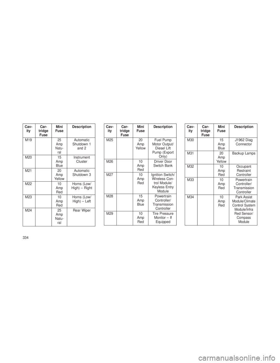
tains cartridge fuses and mini fuses. A descrip-
tion of each fuse and component may be
stamped on the inside cover, otherwise the
cavity number of each fuse is stamped on the
inside cover that corresponds to the following
chart.
Cav-
ity Car-
tridge Fuse Mini
Fuse Description
J01 40 Amp
Green Air Suspension
J02 30 AmpPink Power Liftgate
Module
J03 30 AmpPink Trailer Tow
Totally Integrated Power Module
331
Page 336 of 408
Cav-ity Car-
tridge Fuse Mini
Fuse Description
J04
25
Amp
NaturalDriver Door Node
J05
25
Amp
NaturalPassenger
Door Node
J06 40 Amp
Green Antilock
Brakes Pump/ Stability Con- trol System
J07 30 AmpPink Antilock
Brakes Valve/ Stability Con- trol System
J08 40 Amp
Green Power Seat
J09 30 AmpPink E-Brake
Cav-
ity Car-
tridge Fuse Mini
Fuse Description
J10 30 AmpPink Headlamp
Wash Relay Contact
J11 30 AmpPink Drive Train
Control Module
J12 30 AmpPink Rear Defroster
J13 60 Amp
Yellow Main Ignition
Off Draw (IOD)
J14 20 AmpBlue Trailer Tow
Lamps/Park Lamps
J15 40 Amp
Green Front Cabin
Fan/Blower
J17 40 Amp
Green Starter Motor
SolenoidCav-ity Car-
tridge Fuse Mini
Fuse Description
J18 20 AmpBlue Powertrain
Control
Module/
Powertrain Control
Module/
Transmission Range
J19 60 Amp
Yellow Radiator Fan
Motor HI/
Radiator Fan Motor Low
J20 30 AmpPink Front Wiper
J21 20 AmpBlue
Front/Rear
Washer Control
J2225
Amp
Natural Sunroof Module
332
Page 337 of 408
Cav-ity Car-
tridge Fuse Mini
Fuse Description
M1 15
Amp Blue Stop Lamps
M2 20
Amp
Yellow Electronic
Limit Slip
Differential/Air Suspension
M3 20
Amp
Yellow Liftgate/
Headrest
M5
25
Amp
Natu- ral115V AC
Power Inverter
M6 20
Amp
Yellow Cigar Lighter
M7 20
Amp
Yellow Power Outlet
#2 (Switch- able)
Cav-ity Car-
tridge Fuse Mini
Fuse Description
M8 20
Amp
Yellow Front Heated
Seat & Steer- ing Wheel
M9 20
Amp
Yellow Rear Heated
Seats
M10 15
Amp Blue Video/
Universal
Garage Door Opener
M11 10
Amp Red Heating, Venti-
lation & Air
Conditioning
(Climate Con- trol System)
M12 30
Amp
Green Radio/Amplifier
M13 20
Amp
Yellow Instrument
ClusterCav-ity Car-
tridge Fuse Mini
Fuse Description
M14 20
Amp
Yellow Back Up
Camera – If Equipped
M15 20
Amp
Yellow Power Seat
Module(s)/ Adaptive
Cruise Control/ Audio
Telematics/ Daytime
Running Lights Relay/Air
Suspension Module/
Instrument Cluster
M16 10
Amp Red Occupant
Restraint
Controller
M18 15
Amp Blue Stop Lamp
333
Page 338 of 408
Cav-ity Car-
tridge Fuse Mini
Fuse Description
M19
25
Amp
Natu- ralAutomatic
Shutdown 1 and 2
M20 15
Amp Blue Instrument
Cluster
M21 20
Amp
Yellow Automatic
Shutdown 3
M22 10
Amp Red Horns (Low/
High) – Right
M23 10
Amp Red Horns (Low/
High) – Left
M24 25
Amp
Natu- ral Rear Wiper
Cav-
ity Car-
tridge Fuse Mini
Fuse Description
M25 20
Amp
Yellow Fuel Pump
Motor Output/ Diesel Lift
Pump (Export Only)
M26 10
Amp Red Driver Door
Switch Bank
M27 10
Amp Red Ignition Switch/
Wireless Con- trol Module/
Keyless Entry Module
M28 15
Amp Blue Powertrain
Controller/
Transmission Controller
M29 10
Amp Red Tire Pressure
Monitor – IfEquippedCav- ity Car-
tridge Fuse Mini
Fuse Description
M30 15
Amp Blue J1962 Diag
Connector
M31 20
Amp
Yellow Backup Lamps
M32 10
Amp Red Occupant
Restraint
Controller
M33 10
Amp Red Powertrain
Controller/
Transmission Controller
M34 10
Amp Red
Park Assist
Module/Climate Control System Module/Infra
Red Sensor/ CompassModule
334
Page 339 of 408
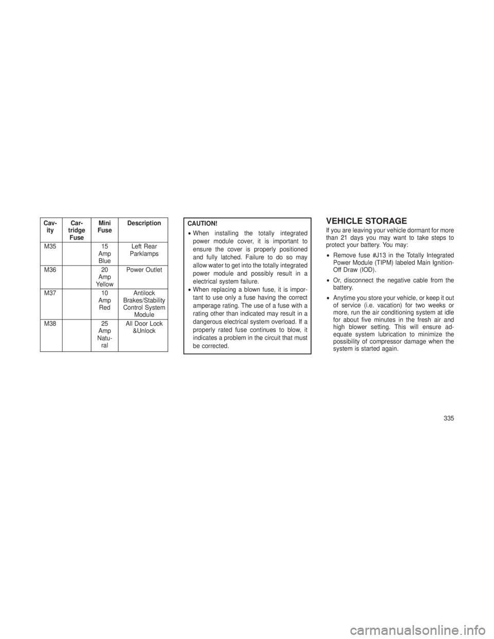
Cav-ity Car-
tridge Fuse Mini
Fuse Description
M35 15
Amp Blue Left Rear
Parklamps
M36 20
Amp
Yellow Power Outlet
M37 10
Amp Red Antilock
Brakes/Stability
Control System Module
M38 25
Amp
Natu- ral All Door Lock
&UnlockCAUTION!
•When installing the totally integrated
power module cover, it is important to
ensure the cover is properly positioned
and fully latched. Failure to do so may
allow water to get into the totally integrated
power module and possibly result in a
electrical system failure.
• When replacing a blown fuse, it is impor-
tant to use only a fuse having the correct
amperage rating. The use of a fuse with a
rating other than indicated may result in a
dangerous electrical system overload. If a
properly rated fuse continues to blow, it
indicates a problem in the circuit that must
be corrected.VEHICLE STORAGE
If you are leaving your vehicle dormant for more
than 21 days you may want to take steps to
protect your battery. You may:
• Remove fuse #J13 in the Totally Integrated
Power Module (TIPM) labeled Main Ignition-
Off Draw (IOD).
• Or, disconnect the negative cable from the
battery.
• Anytime you store your vehicle, or keep it out
of service (i.e. vacation) for two weeks or
more, run the air conditioning system at idle
for about five minutes in the fresh air and
high blower setting. This will ensure ad-
equate system lubrication to minimize the
possibility of compressor damage when the
system is started again.
335
Page 340 of 408
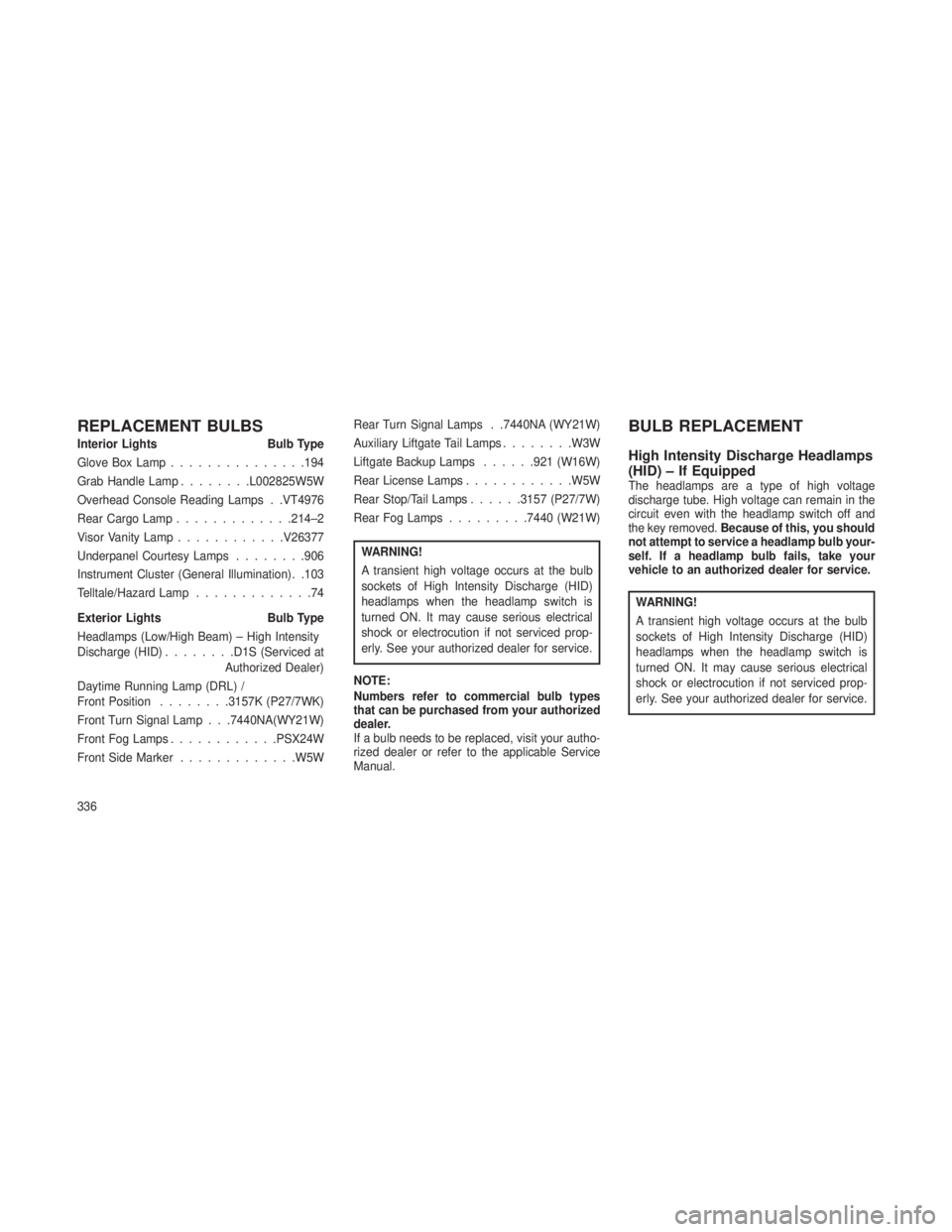
REPLACEMENT BULBS
Interior LightsBulb Type
Glove Box Lamp ...............194
Grab Handle Lamp ........L002825W5W
Overhead Console Reading Lamps . .VT4976
Rear Cargo Lamp .............214–2
Visor Vanity Lamp ............V26377
Underpanel Courtesy Lamps ........906
Instrument Cluster (General Illumination). .103
Telltale/Hazard Lamp .............74
Exterior Lights Bulb Type
Headlamps (Low/High Beam) – High Intensity
Discharge (HID) ........D1S (Serviced at
Authorized Dealer)
Daytime Running Lamp (DRL) /
Front Position ........3157K (P27/7WK)
Front Turn Signal Lamp . . .7440NA(WY21W)
Front Fog Lamps ............PSX24W
Front Side Marker .............W5W Rear Turn Signal Lamps . .7440NA (WY21W)
Auxiliary Liftgate Tail Lamps
........W3W
Liftgate Backup Lamps ......921 (W16W)
Rear License Lamps ............W5W
Rear Stop/Tail Lamps ......3157 (P27/7W)
Rear Fog Lamps .........7440 (W21W)
WARNING!
A transient high voltage occurs at the bulb
sockets of High Intensity Discharge (HID)
headlamps when the headlamp switch is
turned ON. It may cause serious electrical
shock or electrocution if not serviced prop-
erly. See your authorized dealer for service.
NOTE:
Numbers refer to commercial bulb types
that can be purchased from your authorized
dealer.
If a bulb needs to be replaced, visit your autho-
rized dealer or refer to the applicable Service
Manual.
BULB REPLACEMENT
High Intensity Discharge Headlamps
(HID) – If Equipped
The headlamps are a type of high voltage
discharge tube. High voltage can remain in the
circuit even with the headlamp switch off and
the key removed. Because of this, you should
not attempt to service a headlamp bulb your-
self. If a headlamp bulb fails, take your
vehicle to an authorized dealer for service.
WARNING!
A transient high voltage occurs at the bulb
sockets of High Intensity Discharge (HID)
headlamps when the headlamp switch is
turned ON. It may cause serious electrical
shock or electrocution if not serviced prop-
erly. See your authorized dealer for service.
336